Vision Fitness 2200 HRC User manual
- Category
- Bicycles
- Type
- User manual
This manual is also suitable for

ASSEMBLY INSTRUCTIONS
R2200/2200 HRC
To avoid possible damage to this Fitness Cycle,
please follow these assembly instructions.
Carefully remove all its parts from the box,
lay them out and review the parts list.
If any parts are missing, please call 1-800-335-4348, Ext 12
Before proceeding, find your Fitness Cycle’s serial number,
located on the underside of main frame, and enter here:
______________________________
Refer to this number when calling for service.
IT ALL STARTS WITH A VISION

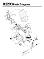
R2200 Parts Diagram

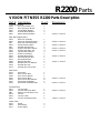
VISION FITNESS R2200 Parts Description
Part # Description Count
Dimensions
Front Wheel Parts
#148 Front Foot Wheel Axle 1
#149 Front Transport Wheels 2
#150 Inside Wheel Washers 2
#185 Outside Wheel Washers 2
#182 Wheel Attachment Bolts 2 20mm L x 8mm D
Rear Rail Support Bars
#106 Rear Foot Assembly 1
#182 Rear Foot Attachment Bolts 4 20mm L x 8mm D
#91 Rear Foot Frame Extension 1
#182 Frame Extension Bolts 4 20mm L x 8mm D
#96 Seat Rail Support Post 1
#186 Support Post Bolts-Bottom 4 55mm L x 8mm D
#182 Support Post Bolts-Top 4 20mm L x 8mm D
#184 Top Post Bolt Washers 4
#121 Aluminum Seat Rail 1
#181 Seat Rail Mount Bolts 2 20mm L x 8mm D
#125 Seat Stop Bumper Rod 1
#124 Seat Stop Bumpers 2
#188 Bumper Rod Bolts 2 10mm L x 3mm D
#189 Bumper Rod Lock Washers 2
#129 Seat Rail End Cap 1
#174 Seat Rail End Cap Screws 2
Seat Parts
#115 Seat Frame 1
#137 Seat Cushion Back 1
#136 Seat Cushion Bottom 1
#195 Seat Cushion Bolts 8 55mm L x 6mm D
#196 Seat Cushion Bolt Washers 8
#110 Seat Mount Handlebars 1
#182 Seat Mount Handlebar Bolts 4 20mm L x 8mm D
Console Parts
#101 Console Mast 1
#182 Console Mast Allen Bolts 6 20mm L x 8mm D
#88 Rubber Console Mast Cover 1
#153 Console 1
#220 Console Cable 1
#197 Console Attachment Bolts 6 11mm L x 5mm D
Other Parts
#152 Pedals 2
#199 Pedal Straps 2
#107 Power Supply 1
R2200 Parts

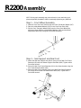
Step 2 • Seat Support and Rear Foot
1: Attach the Seat Rail Support Post (96) to the top of the Rear Foot Frame
Extension (91) with four Bottom Support Post Bolts (186). Tighten with a
5mm Allen wrench.
2: Secure the Rear Foot Frame Extension (91) to the frame bracket using the
four Frame Extension Bolts (182).
3: Secure the Rear Foot Assembly (106) to the Rear Foot Frame Extension
(91) using the four Rear Foot Attachment Bolts (182). Tighten with a
5mm Allen wrench.
NOTE: During each assembly step, ensure that ALL nuts and bolts are in
place and partially threaded in before completely tightening any ONE bolt.
Step 1 • Front Wheel Assembly
1: Slide the Front Foot Axle (148) through the Front Foot Nylon Sleeves (147).
2: Place the Inside Wheel Washers (150) on the Front Foot Axle (148).
3: Slip the Front Transport Wheels (149) onto the Front Foot Wheel Axle
and secure them with the outside Wheel Washers (185) and the Wheel
Attachment Bolts (182) using two 5mm Allen wrenches.
R2200 Assembly

Step 3 • Seat Assembly
1: Secure the Seat Mount Handlebars (110) to the Seat
Frame (115) with four Seat Mount Handlebar Bolts (182).
2: When mounting the Seat Cushion Bottom (136), you
have two sets of holes to choose from. Using the rear
set of holes is recommended for most people. For a
smaller person, you may choose to use the forward set
of bolt holes. Mount the Seat Cushion Bottom (136) to
the Seat Frame (115) with four of the Seat Cushion Bolts
(195) and Seat Cushion Bolt Washers (196) using a 4mm
Allen wrench. Do not fully tighten any bolt until all four
bolts are started.
3: Mount the Seat Cushion Back (137) to the Seat Frame
(115) using the remaining four Seat Cushion Bolts
(195) and Washers (196). Do not fully tighten any bolt
until all four bolts are started.
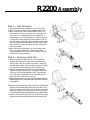
Step 4 • Aluminum Seat Rail
1: Place the Aluminum Seat Rail (121) on the Seat Rail
Support (96) and align the two holes in the Seat Rail
with the two holes in the Frame Lip (299). Thread the
Seat Rail Mount Bolts (182) through the Frame Lip (299)
into the Aluminum Seat Rail but do not tighten yet.
2: Secure the Aluminum Seat Rail (121) to the Seat Rail
Support Post (96) with the four Top Support Post Bolts
(182) and Top Post Bolt Washers (184). Tighten these
four bolts. Now fully tighten the two Seat Rail Mount
Bolts (182) at the front of the seat rail.
3: Slide the Seat Frame (115) onto the Aluminum Seat Rail (121)
while lifting the knob, so the seat frame will slide to the front
of the seat rail.
4: Slide the Seat Stop Bumper Rod (125) with one Seat Stop
Bumper (124) already attached through the hole in the
back of the Aluminum Seat Rail (121). Attach the second
Seat Stop Bumper to the other end of this rod using the
Bumper Rod Screw (188) and Bumper Rod Lock Washer (189).
5: Press the Seat Rail End Cap (129) into the Aluminum Seat
Rail and secure with the Seat Rail End Cap Screws (174).
R2200 Assembly

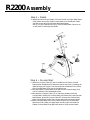
Step 5 • Pedals
1: Identify the left and right Pedals (152) and the left and right Pedal Straps
(199). Attach the correct straps to each pedal, then thread each Pedal
into the correct left and right crank arms and tighten.
NOTE: It is very important to FULLY TIGHTEN each pedal. Failure to do
so will result in loosening and NOISE.
Step 6 • Console Mast
1: Unfold the Console Cable (75) that is folded into the Frame Console
Mast bracket. Straighten this cable and remove any kinks by drawing the
cable through your fingers. Find the string that is attached to the inside
of the Console Mast (101), but do not remove yet.
2: Slide the Rubber Console Mast Cover (88) onto the Console Mast (101)
until it is above the first waterbottle screw.
3: Now attach the Console Cable (75) to the string located inside the
Console Mast. Holding the Console Mast (101) above the Frame Console
Mast Bracket, guide the Console Cable (75) through the Console Mast
while simultaneously sliding the Console Mast onto the frame bracket.
4: Bolt the Console Mast (101) to the frame using the six Console Mast
Allen bolts (182). Make sure these bolts are very tight. Now slide the
Rubber Console Mast Cover (88) back down to cover the bolt heads.
R2200 Assembly

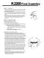
Step 7 • Console
1: Plug the Console Cable (75) into the Console (153). The cable
Connectors are slotted and will only fit properly one way. DO
NOT FORCE the connection.
2: Mount the Console (153) to the Console Mast (101) using the
four Console Attachment Bolts (197). Make sure you DO NOT
PINCH the Console Cable between the Console and the Console
Mast.
3: Plug the Power Supply Cord into the receptacle located at the
base of the Fitness Cycle below the Seat rail. Plug the Power
Supply (107) into an electrical outlet and begin testing
procedures.
Step 8 • Operation Test
Run this simple test prior to using.
1: Choose Intervals program, Level 8.
2: Choose Time of “00:00”, and press Start.
3: Your machine will now operate indefinitely. After several hours
of operation, check for proper functioning of:
A: Resistance Change -- change load one level at a time
using the up and down arrows. Listen for motor noise
(“whirr”) following each change in load, or pedal to feel
load change.
B: Check for display in RPMs while pedaling.
C: Check that all LEDs will light.
Heart Rate Control Console
This console is manufactured with an internal wireless
telemetric receiver that will receive heart rate signals sent to it
by a transmitter that is worn around your chest. This wireless
technology is accurate, continuous, and convenient. You should
be positioned on the Fitness Cycle seat for the system to operate.
1: On the back side of your transmitter are two rubber strips
several inches long. These rubber strips are the electrodes that
will pick up tthe signals of your heart beat. It is very important
to moisten these strips with several drops of water prior to
placing the belt against your chest. This moisture will allow the
signals to be conducted to the transmitting hardware. If you
ever use the bike and the display does not show a heart rate
value, remoisten the electrodes.
2: You will get the best results if you wear the transmitter directly
against your skin. Once these electrodes are moistened, center
the transmitter just below the breast or pectoral muscles with
the Vision Fitness logo centered on the chest and facing out.
Adjust the length of the elastic belt so that the transmitter
presses firmly against your skin, but not so tight as to be
uncomfortable. The transmitter will begin sending a signal as
soon as it is worn.
3: Check for heart rate feedback by testing the console in Heart
Rate mode. Ride the Fitness Cycle at the full range of seat
adjustments to confirm that the console is picking up the
signal from the transmitter.
R2200 Final Assembly
LOGO

621-D East Lake Street
P.O. Box 280
Lake Mills, WI 53551
(920) 648-4090
-
 1
1
-
 2
2
-
 3
3
-
 4
4
-
 5
5
-
 6
6
-
 7
7
-
 8
8


Vision Fitness 2200 HRC User manual
- Category
- Bicycles
- Type
- User manual
- This manual is also suitable for
Ask a question and I''ll find the answer in the document
Finding information in a document is now easier with AI
Related papers
-
Vision Fitness R2000 Assembly Instruction Manual
-
-
-
-
-
-
-
-
-
Other documents
-
ROOMS TO GO HDWOSLSBR Installation guide
-
König SAT-MAFU60 Datasheet
-
Horizon Fitness Avalon100 User guide
-
-
-
Mission MS-300 User manual
-
True Fitness 600U User manual
-
Horizon AVALON II Owner's manual
-
-