Page is loading ...

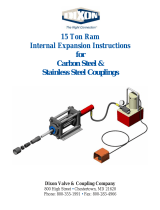
15 Ton Ram
Internal Expansion Instructions
for
Holedall Petroleum
H520 Series Couplings
Dixon Valve & Coupling Company
800 High Street • Chestertown, MD 21620
Phone: 800-355-1991 • Fax: 800-283-4966

2 Dixon Valve & Coupling Co., Call 1-800-355-1991 15 Ton Ram IX 8/06
Ensuring that the ram is fully retracted, remove
the standard base plate.
Select the proper pull rod. For 5/8” and 3/4”
couplings use 15ROSTROD. For 1” through 1 1/2”
couplings use 15RODSMALL.
Note: 15RODSMALL is shown. For 2” through 4”
couplings use 15RODLARGE.
Note: To use 1 1/4” through 4” keyed plugs (from
HMA machine) use 15ROSTROD with keyed shaft
part number 25000HSP10.
Install the pull rod into the base plate of the 15 Ton
Ram.
Select the proper thrust plate. Making sure that
the recess is facing outward towards the
operator, slide the thrust plate over the pull rod
until it reaches the thrust plate holder. Align
the holes in the thrust plate with the dowel pins
on the 15ROSTPA and slide the thrust plate
over the dowel pins until it contacts the face of
the 15ROSTPA.
3
2
1b
1a
Replace the standard base plate with the Holedall
Petroleum thrust plate holder (15ROSTPA).

15 Ton Ram IX 8/06 Dixon Valve & Coupling Co., Call 1-800-355-1991 3
6
5
4b
4a
Slide the stem over the pull rod and into the recess of
the adapter plate with the connection side of the stem
facing the Ram. For male stems, insert the hex into
the recess of the thrust plate. For female stems, insert
the first hex into the thrust plate so that it goes all the
way through then insert the second hex into the
recess of the thrust plate.
Note: Do not lubricate! No additional lubricant is
needed. Stems are pre-lubricated from the factory.
Slide (or screw) the IX plug, small end first, onto
the pull rod and into the shank of the stem.
Note: 1” stem is shown.
Screw the retaining nut (if needed) on until it
contacts the plug. With one hand move the stem
about slightly while tightening the nut or plug
until it is snug.
Accurately measure the hose O.D. with a diameter
tape. Select the correct Holedall Petroleum ferrule
from the DPL based upon the hose O.D. just
measured.
IMPORTANT! If the incorrect ferrule is selected,
failures
will occur. Each hose end must be accu-
rately measured and a ferrule selected based upon
that measurement.
Make sure the hose end is cut square. Measure and
mark the hose in accordance with the provided
Insertion Dimension chart (see page 5). This will
ensure that the proper rubber displacement “pocket”
is maintained when proceeding to Step 7.

4 Dixon Valve & Coupling Co., Call 1-800-355-1991 15 Ton Ram IX 8/06
Holding the hose and ferrule firmly against the
stem shoulder and, maintaining the proper
“pocket”, engage the Ram by stepping on the foot
pedal. The internal expansion operation is
complete when the hose and stem assembly is
pushed completely over the internal expansion
plug. Release the foot pedal. Visually inspect the
coupling.
Note: If the gauge reads 10,000 PSI before internal
expansion is complete, stop. Contact Dixon for
further assistance. During internal expansion
never stand directly in front of the Ram.
Note: For internal expansion of Holedall Carbon Steel and Stainless Steel couplings, please refer to the
Internal Expansion instructions for the 15-Ton Ram using Carbon Steel and Stainless Steel Couplings.
Important! It is a prudent practice to test every length of hose after assembly and Dixon Valve & Coupling
Company recommends this as a standard practice as recommended by the Rubber Manufacturers Association.
Ensuring that the end of the ferrule is aligned with the
mark from Step 6, slide the hose with ferrule over the
shank until the ferrule contacts the shoulder of the stem.
Check to see if the proper pocket is maintained.
IMPORTANT! If there is incorrect “pocket” for the
rubber to displace into, damage may occur to the stem,
ferrule or both, which could result in coupling failure.
7
8

15 Ton Ram IX 8/06 Dixon Valve & Coupling Co., Call 1-800-355-1991 5
Insertion Dimensions for Rostra Fittings
1" ...........................................................25/32"
1¼"........................................................25/32"
1-3/8" ....................................................25/32"
1½"...................................................... 1-1/32"
2" ....................................................... 1-19/32"
2½"........................................................ 2-1/4"
3" ........................................................... 2-3/4"
4" ......................................................... 3-7/32"
Ferrule Sizes Insertion Length
INSERTION LENGTH
FERRULE
/
