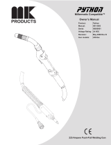
Miller LH490085V User manual

Category
Welding System
Type
User manual

This manual is also suitable for

300 Ampere (Air) Push-Pull Welding Gun
XR - Aluma-Pro
(Air And Water-Cooled Guns)
Processes
Description
MIG (GMAW) Welding
OM-227 398D
200712
Semi-Automatic, Air/Water-
Cooled, MIG (GMAW) Welding
Gun
File: MIG (GMAW)
Visit our website at
www.MillerWelds.com
400 Ampere (Water) Push-Pull Welding Gun
Miller Electric manufactures a full line
of welders and welding related equipment.
For information on other quality Miller
products, contact your local Miller distributor to receive the latest full
line catalog or individual specification sheets. To locate your nearest
distributor or service agency call 1-800-4-A-Miller, or visit us at
www.MillerWelds.com on the web.
Thank you and congratulations on choosing Miller. Now you can get
the job done and get it done right. We know you don’t have time to do
it any other way.
That’s why when Niels Miller first started building arc welders in 1929,
he made sure his products offered long-lasting value and superior
quality. Like you, his customers couldn’t afford anything less. Miller
products had to be more than the best they could be. They had to be the
best you could buy.
Today, the people that build and sell Miller products continue the
tradition. They’re just as committed to providing equipment and service
that meets the high standards of quality and value established in 1929.
This Owners Manual is designed to help you get the most out of your
Miller products. Please take time to read the Safety precautions. They
will help you protect yourself against potential hazards on the worksite.
We’ve made installation and operation quick
and easy. With Miller you can count on years
of reliable service with proper maintenance.
And if for some reason the unit needs repair,
there’s a Troubleshooting section that will
help you figure out what the problem is. The
parts list will then help you to decide the
exact part you may need to fix the problem.
Warranty and service information for your
particular model are also provided.
Miller is the first welding
equipment manufacturer in
the U.S.A. to be registered to
the ISO 9001:2000 Quality
System Standard.
Working as hard as you do
every power source from
Miller is backed by the most
hassle-free warranty in the
business.
From Miller to You
Mil_Thank 4/05
TABLE OF CONTENTS
SECTION 1 SAFETY PRECAUTIONS FOR GMAW WELDING GUNS READ BEFORE USING 1 . . . . . . . .
1-1. Symbol Usage 1 . . . . . . . . . . . . . . . . . . . . . . . . . . . . . . . . . . . . . . . . . . . . . . . . . . . . . . . . . . . . . . . . . . . . . . . .
1-2. Arc Welding Hazards 1 . . . . . . . . . . . . . . . . . . . . . . . . . . . . . . . . . . . . . . . . . . . . . . . . . . . . . . . . . . . . . . . . . .
1-3. EMF Information 2 . . . . . . . . . . . . . . . . . . . . . . . . . . . . . . . . . . . . . . . . . . . . . . . . . . . . . . . . . . . . . . . . . . . . . .
SECTION 2 DEFINITIONS 3 . . . . . . . . . . . . . . . . . . . . . . . . . . . . . . . . . . . . . . . . . . . . . . . . . . . . . . . . . . . . . . . . . . .
2-1. Warning Label Definitions 3 . . . . . . . . . . . . . . . . . . . . . . . . . . . . . . . . . . . . . . . . . . . . . . . . . . . . . . . . . . . . . .
2-2. Manufacturers Rating Label For CE Products Only 4 . . . . . . . . . . . . . . . . . . . . . . . . . . . . . . . . . . . . . . . . .
2-3. WEEE Label (For Products Sold Within The EU) 4 . . . . . . . . . . . . . . . . . . . . . . . . . . . . . . . . . . . . . . . . . . .
2-4. Symbols And Definitions 4 . . . . . . . . . . . . . . . . . . . . . . . . . . . . . . . . . . . . . . . . . . . . . . . . . . . . . . . . . . . . . . .
SECTION 3 INTRODUCTION 5 . . . . . . . . . . . . . . . . . . . . . . . . . . . . . . . . . . . . . . . . . . . . . . . . . . . . . . . . . . . . . . . . .
3-1. Specifications 5 . . . . . . . . . . . . . . . . . . . . . . . . . . . . . . . . . . . . . . . . . . . . . . . . . . . . . . . . . . . . . . . . . . . . . . . .
3-2. Duty Cycle And Overheating 5 . . . . . . . . . . . . . . . . . . . . . . . . . . . . . . . . . . . . . . . . . . . . . . . . . . . . . . . . . . . .
SECTION 4 INSTALLATION 6 . . . . . . . . . . . . . . . . . . . . . . . . . . . . . . . . . . . . . . . . . . . . . . . . . . . . . . . . . . . . . . . . . .
4-1. Connections With A Constant Current (CC), Constant Voltage (CV) Or Constant Current/Constant
Voltage (CC/CV) Welding Power Source Having A 14-Socket Receptacle 6 . . . . . . . . . . . . . . . . . . . . . .
4-2. XR-Water-Cooled Gun Connections 7 . . . . . . . . . . . . . . . . . . . . . . . . . . . . . . . . . . . . . . . . . . . . . . . . . . . . . .
4-3. Millermatic 350P Water Cooled Gun Connections 8 . . . . . . . . . . . . . . . . . . . . . . . . . . . . . . . . . . . . . . . . . .
4-4. Threading Welding Wire For Aluma-Pro Gun And Millermatic 350P 9 . . . . . . . . . . . . . . . . . . . . . . . . . . . .
4-5. Threading Welding Wire Through XR-Control Feeder 10 . . . . . . . . . . . . . . . . . . . . . . . . . . . . . . . . . . . . . . .
4-6. Adjusting Tension At Feeder 10 . . . . . . . . . . . . . . . . . . . . . . . . . . . . . . . . . . . . . . . . . . . . . . . . . . . . . . . . . . . .
4-7. 10-Pin Plug Information 11 . . . . . . . . . . . . . . . . . . . . . . . . . . . . . . . . . . . . . . . . . . . . . . . . . . . . . . . . . . . . . . . .
4-8. Opening Top Cover Of XR-Aluma-Pro Gun 11 . . . . . . . . . . . . . . . . . . . . . . . . . . . . . . . . . . . . . . . . . . . . . . . .
4-9. Threading Welding Wire Through Gun 12 . . . . . . . . . . . . . . . . . . . . . . . . . . . . . . . . . . . . . . . . . . . . . . . . . . . .
SECTION 5 OPERATION 13 . . . . . . . . . . . . . . . . . . . . . . . . . . . . . . . . . . . . . . . . . . . . . . . . . . . . . . . . . . . . . . . . . . . .
5-1. Gun Controls 13 . . . . . . . . . . . . . . . . . . . . . . . . . . . . . . . . . . . . . . . . . . . . . . . . . . . . . . . . . . . . . . . . . . . . . . . . .
5-2. Gun Pressure Roll Tension Setting 13 . . . . . . . . . . . . . . . . . . . . . . . . . . . . . . . . . . . . . . . . . . . . . . . . . . . . . . .
5-3. Shielding Gas 14 . . . . . . . . . . . . . . . . . . . . . . . . . . . . . . . . . . . . . . . . . . . . . . . . . . . . . . . . . . . . . . . . . . . . . . . .
5-4. Coolant Supply For Water-Cooled Models Only 14 . . . . . . . . . . . . . . . . . . . . . . . . . . . . . . . . . . . . . . . . . . . .
5-5. Gun Drive Assembly Maintenance For An XR-Aluma-Pro Gun 15 . . . . . . . . . . . . . . . . . . . . . . . . . . . . . . . .
5-6. Replacing Head Tube Liner In XR-Aluma-Pro Guns 16 . . . . . . . . . . . . . . . . . . . . . . . . . . . . . . . . . . . . . . . . .
5-7. Changing Gun Contact Tip 16 . . . . . . . . . . . . . . . . . . . . . . . . . . . . . . . . . . . . . . . . . . . . . . . . . . . . . . . . . . . . .
5-8. Replacing The Gun Liner On XR-Aluma-Pro Guns 17 . . . . . . . . . . . . . . . . . . . . . . . . . . . . . . . . . . . . . . . . . .
SECTION 6 MAINTENANCE & TROUBLESHOOTING 18 . . . . . . . . . . . . . . . . . . . . . . . . . . . . . . . . . . . . . . . . . . .
6-1. Routine Maintenance For Aluminum Push/Pull Guns 18 . . . . . . . . . . . . . . . . . . . . . . . . . . . . . . . . . . . . . . . .
6-2. Cleaning The Gun Liner On XR-Aluma-Pro Guns 19 . . . . . . . . . . . . . . . . . . . . . . . . . . . . . . . . . . . . . . . . . . .
6-3. Troubleshooting Table 20 . . . . . . . . . . . . . . . . . . . . . . . . . . . . . . . . . . . . . . . . . . . . . . . . . . . . . . . . . . . . . . . . .
SECTION 7 ELECTRICAL DIAGRAMS 21 . . . . . . . . . . . . . . . . . . . . . . . . . . . . . . . . . . . . . . . . . . . . . . . . . . . . . . . .
SECTION 8 PARTS LIST 22 . . . . . . . . . . . . . . . . . . . . . . . . . . . . . . . . . . . . . . . . . . . . . . . . . . . . . . . . . . . . . . . . . . . . .
SECTION 9 PARTS LIST INCLUDING CONSUMABLES 27 . . . . . . . . . . . . . . . . . . . . . . . . . . . . . . . . . . . . . . . . .
OPTIONS AND ACCESSORIES
WARRANTY
dec_wire_6/05
Declaration of Conformity for
European Community (CE) Products
This information is provided for units with CE certification (see rating label on unit).
NOTE
Manufacturer: European Contact:
Miller Electric Mg. Co. Mr. Danilo Fedolfi,
1635 W. Spencer St. Managing Director
Appleton, WI 54914 USA ITW Welding Products Italy S.r.l.
Phone: (920) 734-9821 Via Privata Iseo 6/E
20098 San Giuliano
Milanese, Italy
Phone: 39(02)98290-1
Fax: 39(02)98290203
European Contact Signature:
Declares that the product: XR - Aluma-Pro
conforms to the following Directives and Standards:
Directives
Low Voltage Directive: 73/23/EEC
Electromagnetic Compatibility (EMC) Directive: 89/336/EEC
Standards
Arc Welding Equipment Part 5: Wire Feeders. IEC 60974-5 Ed. 1
Arc Welding Equipment Part 10: Electromagnetic Compatibility (EMC) Requirements. IEC 60974-10 August 2002
Arc Welding Equipment Part 1: Welding Power Sources. IEC 60974-1 Ed. 2.1
Degrees Of Protection Provided By Enclosure (IP Code) IEC 60529 Ed. 2.1
Insulation Coordination For Equipment Within Low-Voltage Systems
Part 1: Principles, Requirements and Tests: IEC 60664-1 Ed. 1.1
Arc Welding Equipment Part 7: Torches. IC 60974-7 Ed.1
The product technical file is maintained by the responsible Business Unit(s) located at the manufacturing facility.
OM-227 398 Page 1
SECTION 1 SAFETY PRECAUTIONS FOR GMAW
WELDING GUNS READ BEFORE USING
SR7_200704
Protect yourself and others from injury — read and follow these precautions.
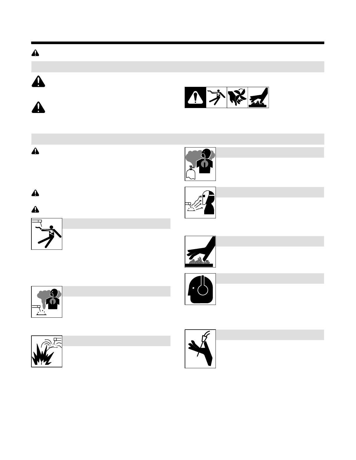
1-1. Symbol Usage
DANGER! Indicates a hazardous situation which, if
not avoided, will result in death or serious injury. The
possible hazards are shown in the adjoining symbols
or explained in the text.
Indicates a hazardous situation which, if not avoided,
could result in death or serious injury. The possible
hazards are shown in the adjoining symbols or ex-
plained in the text.
NOTICE Indicates statements not related to personal injury.
. Indicates special instructions.
This group of symbols means Warning! Watch Out! ELECTRIC
SHOCK, MOVING PARTS, and HOT PARTS hazards. Consult sym-
bols and related instructions below for necessary actions to avoid the
hazards.
1-2. Arc Welding Hazards
The symbols shown below are used throughout this manual
to call attention to and identify possible hazards. When you
see the symbol, watch out, and follow the related instructions
to avoid the hazard. The safety information given below is
only a summary of the more complete safety information
found in the welding power source Owners Manual. Read
and follow all Safety Standards.
Only qualified persons should install, operate, maintain, and
repair this unit.
During operation, keep everybody, especially children, away.
ELECTRIC SHOCK can kill.
D Always wear dry insulating gloves.
D Insulate yourself from work and ground.
D Do not touch live electrode or electrical parts.
D Repair or replace worn, damaged, or cracked gun or cable insula-
tion.
D Turn off welding power source before changing contact tip or gun
parts.
D Keep all covers and handle securely in place.
D Keep your head out of the fumes.
D Ventilate area, or use breathing device.
D Read Material Safety Data Sheets (MSDSs)
and manufacturer’s instructions for material
used.
FUMES AND GASES can be hazardous.
D Do not weld near flammable material.
D Do not weld on closed containers.
D Watch for fire; keep extinguisher nearby.
WELDING can cause fire or explosion.
BUILDUP OF GAS can injure or kill.
D Shut off shielding gas supply when not in use.
D Always ventilate confined spaces or use ap-
proved air-supplied respirator.
D Wear welding helmet with correct shade of fil-
ter.
D Wear correct eye and body protection.
D Cover exposed skin with spatter-resistant
clothing.
ARC RAYS can burn eyes and skin.
HOT PARTS can cause severe burns.
D Allow gun to cool before touching.
D Do not touch hot metal.
D Protect hot metal from contact by others.
NOISE can damage hearing.
Noise from some processes or equipment can
damage hearing.
D Check for noise level limits exceeding those
specified by OSHA.
D Use approved ear plugs or ear muffs if noise level is high.
D Warn others nearby about noise hazard.
WELDING WIRE can cause injury.
D Keep hands and body away from gun tip when
trigger is pressed.
OM-227 398 Page 2
1-3. EMF Information
Considerations About Welding And The Effects Of Low Frequency
Electric And Magnetic Fields
Welding current, as it flows through welding cables, will cause electro-
magnetic fields. There has been and still is some concern about such
fields. However, after examining more than 500 studies spanning 17
years of research, a special blue ribbon committee of the National
Research Council concluded that: “The body of evidence, in the
committee’s judgment, has not demonstrated that exposure to power-
frequency electric and magnetic fields is a human-health hazard.”
However, studies are still going forth and evidence continues to be
examined. Until the final conclusions of the research are reached, you
may wish to minimize your exposure to electromagnetic fields when
welding or cutting.
To reduce magnetic fields in the workplace, use the following
procedures:
1. Keep cables close together by twisting or taping them, or using a
cable cover.
2. Arrange cables to one side and away from the operator.
3. Do not coil or drape cables around your body.
4. Keep welding power source and cables as far away from
operator as practical.
5. Connect work clamp to workpiece as close to the weld as
possible.
About Implanted Medical Devices:
Implanted Medical Device wearers should consult their doctor and the
device manufacturer before performing or going near arc welding, spot
welding, gouging, plasma arc cutting, or induction heating operations.
If cleared by your doctor, then following the above procedures is recom-
mended.
OM-227 398 Page 3
SECTION 2 DEFINITIONS
1 1.1 1.2 1.3
3 3.1 3.2 3.3
4 4.1
+
2
2.1
2.2
+
+
56
+
2.3
S-178 936
A. Warning! Watch Out! There
are possible hazards as
shown by the symbols.
B. Drive rolls can injure fingers.
C. Welding wire and drive parts
are at welding voltage during
operation keep hands and
metal objects clear.
1 Electric shock can kill.
1.1 Wear dry insulating gloves.
Do not touch electrode with
bare hand. Do not wear wet or
damaged gloves.
1.2 Protect yourself from electric
shock by insulating yourself
from work and ground.
1.3 Disconnect input plug or
power before working on
machine.
2 Breathing welding fumes can
be hazardous to your health.
2.1 Keep your head out of the
fumes.
2.2 Use forced ventilation or local
exhaust to remove the fumes.
2.3 Use ventilating fan to remove
fumes.
3 Welding sparks can cause
explosion or fire.
3.1 Keep flammables away from
welding. Don’t weld near
flammables.
3.2 Welding sparks can cause
fires. Have a fire extinguisher
nearby and have a watch
person ready to use it.
3.3 Do not weld on drums or any
closed containers.
4 Arc rays can burn eyes and
injure skin.
4.1 Wear hat and safety glasses.
Use ear protection and button
shirt collar. Use welding
helmet with correct shade of
filter. Wear complete body
protection.
5 Become trained and read the
instructions before working on
the machine or welding.
6 Do not remove or paint over
(cover) the label.
2-1. Warning Label Definitions
ABC
OM-227 398 Page 4
2-2. Manufacturers Rating Label For CE Products Only
229 109-A
2-3. WEEE Label (For Products Sold Within The EU)
Do not discard product (where ap-
plicable) with general waste.
Reuse or recycle Waste Electrical
and Electronic Equipment (WEEE)
by disposing at a designated collec-
tion facility.
Contact your local recycling office
or your local distributor for further
information.
2-4. Symbols And Definitions
. Some symbols are found only on CE products.
A
Amperes
V
Volts Alternating Current
X
Duty Cycle
IP
Degree Of
Protection
Hz
Hertz Circuit Breaker Wire Feed
Jog Output Trigger Gun
Press To Set Increase Trigger Hold On Trigger Hold Off
Purge Spot Weld Time Percent Run-In
Burnback Time
U
1
Primary Voltage
U
2
Load Voltage Read Instructions
I
1
Primary Current
I
2
Rated Current Line Connection
Water (Coolant) In-
put
Water (Coolant)
Output
Fuse
Continuous
Spot Welding
OM-227 398 Page 5
SECTION 3 INTRODUCTION
3-1. Specifications
Model Welding Output Range Electrode
Wire Diameter
Capacity
Wire Feed
Speed Range
Net Weight
(Torch Only)
XR-Aluma-Pro Gun
(Air Cooled)
300 A at 100% Duty Cycle
with 15, 25 or 35 ft
(4.6 or 7.6 m) gun
.030 To 1/16 in
(0.8 To 1.6 mm)
aluminum wire
70 To 900 ipm
(1.8 To 23 mpm)
2.5 lb (1.1 kg)
(less cables)
XR-Aluma-Pro Gun
(Water Cooled)
400 A at 100% Duty Cycle
with 15, 25 or 35 ft
(4.6 or 7.6 m) gun
.030 To 1/16 in
(0.8 To 1.6 mm)
aluminum wire
70 To 900 ipm
(1.8 To 23 mpm)
2.9 lb (1.3 kg)
(less cables)
. When changing 1/16 in (1.6 mm) wire, kit 230708 must be installed.
3-2. Duty Cycle And Overheating
Duty Cycle is percentage of 10 min-
utes that unit can weld at rated load
without overheating.
NOTICE Exceeding duty cycle
can damage unit and void warranty.
sduty1 5/95
Continuous Welding
Air-Cooled Models
Water-Cooled Models
Continuous Welding
100% Duty Cycle At 300 Peak Amperage Using 100% Argon Gas w/15, 25 Or 35 Foot Guns
100% Duty Cycle At 400 Peak Amperage Using 100% Argon Gas w/15, 25 Or 35 Foot Guns
OM-227 398 Page 6
SECTION 4 INSTALLATION
. Be sure that contact tip, liner, and drive rolls are correct for wire size and type. See Parts List to change parts as needed.
4-1. Connections With A Constant Current (CC), Constant Voltage (CV) Or Constant
Current/Constant Voltage (CC/CV) Welding Power Source Having A 14-Socket Re-
ceptacle
804 542-B / 804 653-A
1 CC, CV Or CC/CV Welding
Power Source
2 24 VAC/Contactor Control
14-Pin Plug
3 Workpiece
4 Voltage Sensing Lead
(Optional)
Connect lead to workpiece for CC
welding only.
5 Gun
6 Wire Feeder
7 24 VAC/Contactor Control
Cord
! Do not use gas pressure
above 50 psi (345 kPa).
8 Gas Cylinder
1
2
3
4
5
7
8
6
Millermatic 350P
XR Control
5
1
8
OM-227 398 Page 7
4-2. XR-Water-Cooled Gun Connections
Ref. 801 577-A / 805 106-A
. Turn on coolant supply before
welding or gun will be dam-
aged.
1 Gun Control Cable
Insert plug into Gun Control
receptacle, and tighten threaded
collar.
2 Gun Connector
3 Gun Securing Knob
4 Gun Connector Block
Loosen gun securing knob, and
insert gun connector through Wire
opening until it bottoms against
block. Tighten knob. Close and
latch door.
5 Gun (Coolant) “In” Hose
Connect to Water “In” fitting on
feeder (left-hand threads).
6 Gun (Coolant) “Out” Hose
Connect to Water “Out” fitting on
feeder (left-hand threads)
7 Water (Coolant) Output
8 Water (Coolant) Input
9 XR Control (Coolant) Output
10 XR Control (Coolant) Input
Close and latch door.
Tools Needed:
1
5
6
9/16 in
4
3
2
Left Side
7
8
9
10
OM-227 398 Page 8
4-3. Millermatic 350P Water Cooled Gun Connections
Ref. 804 945-A
. Turn on coolant supply before welding
or gun will be damaged.
1 Coolant Supply
2 Millermatic 350P
3 Gun Control Cable
Insert plug into gun control receptacle and
tighten threaded collar.
4 Water In Hose
Connect to coolant supply with supplied
coupler and water hose (left-hand threads).
5 Gun Connector
Loosen gun securing knob, and insert gun
connector through Wire opening until it
bottoms against block. Tighten knob. Close
and latch door.
6 Water Out Hose
Connect to coolant supply with supplied
coupler and water hose (left-hand threads).
7 Coolant “In”
8 Coolant “Out”
Tools Needed:
5
9/16 in
6
4
3
1
2
8
7
OM-227 398 Page 9
4-4. Threading Welding Wire For Aluma-Pro Gun And Millermatic 350P
1 Wire Spool
2 Welding Wire
3 Inlet Wire Guide
4 Drive Roll
5 Intermediate Wire Guide
6 Outlet Wire Guide
7 Pressure Adjustment Knob
8 Gun Conduit Cable
Lay gun cable out straight.
Tools Needed:
6 in
(150 mm)
. Hold wire tightly to keep it
from unraveling.
Open pressure assembly.
Pull and hold wire; cut off end.
Push wire thru guides into gun;
continue to hold wire.
Close and tighten pressure
assembly, and let go of wire.
. Set pressure indicator
scale to 1/2 lb.
Ref. 803 544-A / 218 243-A / 218 244-A / S-0627-A
1
2
3
4
Pressure
Indicator
Scale
218243−A
IMPORTANT!
For Aluminum Push−Pull welding.
Thread hub tension nut loosely
IMPORTANT!
For Aluminum
Push−Pull welding.
1
2
3
4
218244−A
7
8
35621 4
See Section 4-9 for threading welding
wire through Aluma-Pro guns.
3/4 in
Tighten to
1/2 lb.
OM-227 398 Page 10
4-5. Threading Welding Wire Through XR-Control Feeder
Ref. 802 193-A
Tools Needed:
2
1
1 Cable Assembly
Lay cable assembly out straight.
2 Jog Switch
Push Jog switch up to feed wire through
cable assembly.
. Hold wire tightly to keep
it from unraveling.
4-6. Adjusting Tension At Feeder
Ref. 802 193-A
Tools Needed:
Pull and hold wire; cut off end.
6 in
(150 mm)
Open tension arm.
Thread wire thru inlet guide, along drive roll groove, and
into wire conduit. Close tension arm. Adjust tension as
follows: grasp spool with one hand, press Jog switch, and
turn thumb nut clockwise until motor stalls when Jog
switch is pressed. Back thumb nut off slightly.
Proceed to Section 4-9.
OM-227 398 Page 11
4-7. 10-Pin Plug Information
10
Pin* Pin Information
A Electrode sense lead
B Motor Common
E
F
G Trigger
F
D
J
G
C Motor 0 to +24 volts dc with respect to pin B
G
C
I
H
D Trigger
H
B
A
E Wire speed Ref. +9 volts dc
H Wire speed com
F Wire speed 0 to +9 volts dc with respect to pin H
J Gun sensing resistor with respect to pin H
I Not used
4-8. Opening Top Cover Of XR-Aluma-Pro Gun
1 Top Cover
Squeeze sides of cover and lift up
as shown.
To close cover, pivot cover closed
on gun, and push cover down until
cover locks tight.
Ref. 804 544-B
1
OM-227 398 Page 12
! Welding wire is electrically live when
gun trigger is used to jog wire.
. Refer to Section 4-4 for instructions on feeding
wire through feeder.
4-9. Threading Welding Wire Through Gun
Ref. 804 544-B / 804 545-B
Tools Needed:
Lay gun cable out straight. Press Jog switch until about 6
in (152 mm) of wire is sticking out end of contact tip.
Cut off wire. Close and
latch wire feeder door.
. Turn OFF coolant supply before threading wire
through gun..
For XR-Aluma-Pro Gun:
. Verify pressure adjustment
on handle matches the wire
type. See Section 5-2.
OM-227 398 Page 13
SECTION 5 OPERATION
5-1. Gun Controls
1 Trigger
Press trigger to energize welding
power source contactor (if
applicable), start shielding gas flow,
and begin wire feed.
Switches inside the wire feeder can
be set to provide timed shielding
gas preflow and postflow when
trigger is pressed and released.
When this feature is turned Off, no
preflow or postflow is provided for
the welding operation.
2 Gun Wire Speed Control
Use control to fine adjust wire feed
speed set on XR-Control. Gun Wire
Speed Control has 3-3/4 turns of
adjustment from minimum to maxi-
mum.
1
2
Ref. 804 545-B
5-2. Gun Pressure Roll Tension Setting
. Aluminum series specific -
Pressure roll tension setting
ensures smooth wire feeding
action.
. Gun Pressure Roll Tension is
factory set to 4XXX.
1 Pressure Roll Adjustment
Screw
Wire tension should be set to 4XXX
for 4000 series aluminum wire.
Rotate Pressure Roll Adjustment
Screw fully counterclockwise until
indicator line on adjustment knob
lines up with indicator line on handle
in the 4XXX position.
Wire tension should be set to 5XXX
for 5000 series aluminum and stain-
less wire.
Rotate Pressure Roll Adjustment
Screw fully clockwise until indicator
line on adjustment knob lines up
with indicator line on handle in the
5XXX position.
1
Ref. 804 545-B
Tools Needed:
OM-227 398 Page 14
5-3. Shielding Gas
Ref. 151 666-F / 804 545-B
1 Shielding Gas Cylinder
2 Valve
3 Gun Trigger
Open valve on cylinder just before
welding.
Gun trigger turns weld output and
gas flow on and off (see Section
5-1).
Close valve on cylinder when
finished welding.
3
1
2
5-4. Coolant Supply For Water-Cooled Models Only
Ref. 150 755-A
1 Coolant Supply
2 Coolant “In”
3 Coolant “Out”
See table below for coolant
guidelines.
Turn On coolant supply before
welding.
Turn Off coolant supply when
finished welding.
1
MILLER Low
Conductivity Coolant
No. 043 810**
MILLER Aluminum Protecting
Coolant No. 043 809**;
Distilled Or Deionized Water OK
Above 32° F (0° C)
GTAW Or Where
HF* Is Used
GMAW Or Where Coolant
Contacts Aluminum Parts Or
Where HF* Not Used
Application
*HF: High Frequency Current
**MILLER coolants protect to -37° F (-38°C) and resist algae growth.
Coolant
3
2
OM-227 398 Page 15
5-5. Gun Drive Assembly Maintenance For An XR-Aluma-Pro Gun
Ref. 804 544-B
1 Lever Arm
Using lever arm open pressure roll
with bearing as shown.
Retract wire onto spool.
2 Drive Roll
Use wire brush to clean drive roll.
Install drive roll with hex opening
down toward shaft hex, and secure
with screw.
3 Pressure Roll
Thread welding wire through gun.
Close pressure roll assembly and
idler roll (located in XR control box).
Press jog switch until wire is stick-
ing out end of contact tip.
. When changing wire size and
using an XR control box you
should change the control box
drive roll and idler. See XR
owners manual for details.
Close top cover.
Tools Needed:
5/16 in
3
2
1
OM-227 398 Page 16
5-6. Replacing Head Tube Liner In XR-Aluma-Pro Guns
Ref. 804 544-B
. Turn OFF coolant supply before
removing head tube on
water-cooled gun.
The standard head tube liner will ac-
commodate wire diameters from
.030-.035 wire size.
When changing wire size, change
control box drive roll, idler and head
tube liner with appropriate sized lin-
er.
1 Head Tube
2 Head Tube Nut
Loosen head tube nut and remove
head tube from gun.
3 Head Tube Liner
Pull liner out of head tube.
Insert new liner into head tube (install
tapered end first) and reinstall head
tube onto gun.
. A twisting motion may be need-
ed to feed liner thru head tube.
. Be sure head tube is seated and
head tube nut is securely tight-
ened before operating gun. If
head tube nut is not adequately
tightened, unwanted arcing may
occur between head tube and
gun housing.
1
2
3
Tapered end
5-7. Changing Gun Contact Tip
Ref. 804 709-A
2
1
Remove nozzle
1 Nozzle
2 FasTip
Unscrew FasTip.
Install new FasTip.
. Make sure correct size con-
tact tip is being used. Incor-
rect size may cause arcing in-
side tip, poor feedability and
poor arc starting characteris-
tics(see Section 9).
Reinstall nozzle.
  • Page 1 1
  • Page 2 2
  • Page 3 3
  • Page 4 4
  • Page 5 5
  • Page 6 6
  • Page 7 7
  • Page 8 8
  • Page 9 9
  • Page 10 10
  • Page 11 11
  • Page 12 12
  • Page 13 13
  • Page 14 14
  • Page 15 15
  • Page 16 16
  • Page 17 17
  • Page 18 18
  • Page 19 19
  • Page 20 20
  • Page 21 21
  • Page 22 22
  • Page 23 23
  • Page 24 24
  • Page 25 25
  • Page 26 26
  • Page 27 27
  • Page 28 28
  • Page 29 29
  • Page 30 30
  • Page 31 31
  • Page 32 32
  • Page 33 33
  • Page 34 34
  • Page 35 35
  • Page 36 36

Miller LH490085V User manual

Category
Welding System
Type
User manual
This manual is also suitable for

Ask a question and I''ll find the answer in the document

Finding information in a document is now easier with AI