Wasp Bar Code WLP 4170 CCD User manual
- Category
- Bar code readers
- Type
- User manual
This manual is also suitable for

Wasp WLP 4170 CCD
Programming Guide
Please Read
Note:
The Wasp
WLP 4170 CCD
Scanner is ready to scan the
most popular bar codes out of the box. This manual
should only be used to make changes in the
configuration of the scanner for specific applications.
This scanner does not require software or drivers to
operate.The scanner enters data as keyboard data. Please
review this manual before scanning any of the programming
bar codes in this manual.
TechTip
If you are unsure of the scanner configuration or have
scanned the incorrect codes, please scan the default
bar code on page 6.This will reset the scanner to its
factory settings.

© Copyright Wasp Technologies 2002.
All rights reserved.
Version 1.0
No part of this publication may be reproduced or transmitted in any form
or by any means without the written permission of Wasp Technologies.
The information contained in this document is subject to change without
notice.
Wasp is a trademark of Wasp Technologies. All other trademarks or registered trademarks are the
property of their respective owners.

Table of Contents
Chapter 1. Introduction..............................................................................1
Chapter 2. Installation................................................................................2
Chapter 3. Quick Start ..............................................................................3
Chapter 4. Bar Code Symbologies............................................................4
Chapter 5. Setup & Configuration........................................................5-34
1. Factory Default ..........................................................6
2. Beep and Delay..........................................................7
3. Intercharacter Delay ..................................................8
4. Keyboard Wedge........................................................9
5. Scanning Modes ......................................................10
6. Preamble/Postamble Configuration..........................11
5. Bar Code Symbology..........................................12-29
Code 39......................................................12-13
Code 128....................................................14-15
UPC-A ........................................................16-17
UPC-E ........................................................18-19
EAN-13 ......................................................20-21
EAN-8 ........................................................22-23
Code 93 ..........................................................24
Interleaved 2 of 5 ............................................25
Codabar......................................................26-27
MSI/Plessey ....................................................28
PDF417............................................................29
Appendix A. Bar Code Test Symbols....................................................30-33
Specifications ........................................................................34
Product Support, Warranty....................................................35
ASCII Code Table..................................................................36

1
Chapter 1
Introduction
Bar coding is the most common Automated Data Collection (ADC) technology
providing timely, error-free information that can be used to increase productivity,
accuracy, and efficiency in the workplace. Virtually every type of industry is
using bar codes to replace keyboard data entry. Studies have shown that a
proficient data entry operator will make one error for every 300 characters that
are manually entered. The error rate using bar codes is almost negligible and
can be error-free using bar code symbologies with the check digit enabled.
The Wasp Charged Coupled Device (CCD) technology is a technique whereby a
bar code is photographed, digitized, and electronically sampled by built-in
photodetectors. The detectors process the measurement of every bar and
space using the number of adjacent photodetectors which contrast a black mark
and a white space.Wasp WLP 4170 CCD is extremely rugged since it has no
moving parts. Wasp WLP 4170 CCD reader supports PC AT/XT and PS/2
keyboard interfaces and easily wedges between the computer and keyboard.
Bar code data is passed directly into the keyboard buffer as if it had been typed
in by hand by a data entry operator.
Of all the hand held bar code scanning devices on the market, the CCD reader
is the easiest to use and most cost effective for the typical business user.To
activate the scanner, the user simply points the scanning aperture towards the
bar code, pulls the trigger, and aims the red LED beam across the bar code.

2
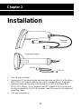
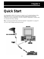
1. Turn off your computer.
2. Unplug your PC keyboard cable and plug the male end (Din 5) of the Wasp
WLP 4170 CCD Scanner directly into your PC keyboard port. Plug your
keyboard cable into the other end (female Din 5) of the the Wasp WLP
4170 CCD Scanner. If your keyboard and PC support a Din 6 connection,
use the enclosed Din 5 to Din 6 converter cable to connect to the keyboard
power tap cable.
3. Turn your computer on.
Chapter 2
Installation
Keyboard
Y-Cable
Din-5F
Din-6M
Scanning Aperture

3
Your Wasp WLP 4170 CCD Scanner is ready to go. The default settings of the
Wasp WLP 4170 CCD Scanner have been pre-programmed for the most
common bar code configurations. Use the "Setup & Configuration" sections only
to customize the Wasp settings.
Tip: Use the pre-printed "Bar Code Test Symbols" in Appendix A on page 30
as a test chart to begin practicing scanning.
Chapter 3
Quick Start

4
Bar codes are symbols consisting of a series of bars and spaces which can be
applied to packages, cartons, bottles, and other commercial products. The bars
and spaces in each symbol are grouped in such a way to represent a specific
ASCII character or function. The interpretation of these groups is based on a
particular set of rules called symbologies. Various symbologies have been
developed for particular applications. Some examples are shipping and
receiving, manufacturing, retail, healthcare, transportation, document processing
and tracking, and libraries.
The resolution of a bar code is dependent on the narrowest element of a bar
code (X dimension), and can vary from high density (nominally less than 0.009
in./0.23 mm), medium density (between 0.009 in./0.23 mm and 0.020 in./0.50
mm), and low density (greater than 0.020 in./0.50 mm). Medium and low
densities are the most common since these are the easiest to read (scan) with
nearly all scanning devices.Wasp WLP 4170 CCD Scanner can read bar codes
with X-dimensions as low as 4 mils (0.10mm).
Wasp WLP 4170 CCD Scanner can read the most popular linear bar code
symbologies including Code 39, Code 93, Code 128, Interleaved 2 of 5, UPC-A,
UPC-E, EAN/JAN-8, EAN/JAN-13, Codabar, and MSI Plessey, and also the 2D
bar code symbology PDF417.
Please see test chart on pages 30-33.
Chapter 4
Bar Code Symbologies

5
In order to configure Wasp WLP 4170 CCD Scanner, you must familiarize
yourself with the setup procedures on the following pages.The default settings
of Wasp WLP 4170 CCD Scanner are identified on each page and clearly
marked using an asterisk (*). The default settings have been preprogrammed
for the most common bar code configurations. Use the Setup &
Configuration only to customize the Wasp settings. If you need to configure
Wasp WLP 4170 CCD Scanner, the default settings will be overwritten.All the
programmed settings are stored permanently in non-volatile memory.Therefore,
your configuration will be maintained even if keyboard power to Wasp WLP 4170
CCD Scanner is removed by turning off your PC.
In order to configure Wasp WLP 4170 CCD Scanner, seven basic steps need to
be followed for each programmed setting:
(1) Determine what, if any, options on EACH PAGE that you wish to change.
(2) Scan the "Begin" bar code. WLP 4170 CCD Scanner will sound an
ascending tone to indicate that setup is in progress.
(3) Scan the bar code representing the option to be changed.
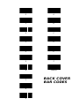
(4) Scan the bar codes representing the option values (e.g. 01, 02, 3A etc.).
These option values can be found on the inside back cover flap of this
manual. You must scan two digits for each option setting.
(5) Repeat the above two steps, if necessary, to change the options in the same
group.
(6) Scan the “Set” bar code on the back cover flap to confirm your selections.
(7) Scan the "Exit" bar code to exit the group currently selected. Wasp WLP
4170 CCD Scanner will sound a descending tone.
NOTE: Pages 6 and 7 are designed as walk through example
pages. Use these pages as examples on how to change
an option for the rest of the manual.
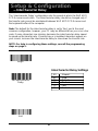
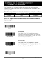
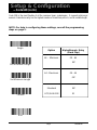
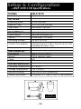
Chapter 5
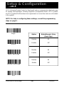
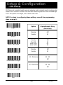
Setup & Configuration

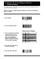
NOTE: Scanning these bar codes returns the scanner to
the factory default settings
1. Scan “Begin ”
2. Scan “Default” to restore
scanner to default settings
6
Tip: Use this configuration to restore the factory default settings if you are
unsure how your scanner has been configured. The 'Factory Default'
configuration is very useful when you need to reprogram your Wasp
WLP 4170 CCD Scanner after the defaults have been changed. By setting
the default configuration, the user knows precisely the configuration for each
programmed setting.
Setup & Configuration
—Factory Default
Begin
Default

7
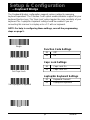
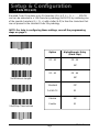
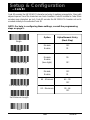
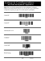
Setup & Configuration
—Beep and Delay
Beep Volume Settings
00 None
01 Lowest
02 Low
03 Medium (Default)
04 Medium-High
05 High
06 High-Medium
07 Highest
The 'Beep Volume' configuration changes the volume of the audible indicator of
the WLP 4170 CCD Scanner.
NOTE: For help in configuring these settings, consult the programming
steps on page 5.
1. Scan “Begin ”
2. Scan “Set Beep Volume”
4. Scan the “Set” barcode on
the back cover flap
5. Scan the “Exit” barcode
3. Pick a setting from the table
at right, then turn to the
back cover flap and scan
the corresponding two
digits. For example: if you
desire no beep, scan 0 and
0 on the back cover flap
Begin
Set Beep Volume
Exit

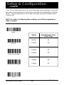
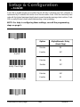
8
Setup & Configuration
—Intercharacter Delay
Intercharacter Delay Settings
00 Slowest
01 Slow
02 Default
50 Medium
75 Fast
99 Fastest
The 'Intercharacter Delay' configuration sets the speed at which the WLP 4170
CCD Scanner sends data. The intercharacter delay should be changed only if
the transfer rate cannot be maintained between WLP 4170 CCD Scanner and
the keyboard buffer of the computer.
Note: The default for the intercharacter delay is set to '2ms' and is the most
common configuration; however, your PC may be different.When you scan a bar
code, if some characters are missing, decrease the intercharacter delay speed
to speed up the transfer rate. If some stray or scrambled characters appear on
your screen, increase the intercharacter delay to slow down the transfer rate.
NOTE: For help in configuring these settings, consult the programming
steps on page 5.
Begin
Set Intercharacter
Delay
Exit

9
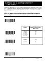
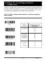
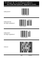
Setup & Configuration
—Keyboard Wedge
00 Keyboard Present*
01 Laptop/No keyboard
The 'Keyboard Wedge' configuration supports options related to managing
keyboard operations.The 'Function Code' option enables/disables support for your
keyboard function keys.The 'Caps Lock' option toggles the case sensitivity of your
keyboard.The ‘Laptop/No Keyboard’ setting should be enabled if you are
connecting this scanner to a laptop or to a PC with no keyboard.
NOTE: For help in configuring these settings, consult the programming
steps on page 5.
Laptop/No Keyboard Settings
00 Off*
01 On
Function Code Settings
00 Caps Lock On
01 Caps Lock Off*
Caps Lock Settings
*Default
Begin
Set Caps Lock
Set Laptop/No Keyboard
Set Function Code
Exit

*Default
00 Default* 04 Continuous
10
Setup & Configuration
—Scanning Modes
Begin
Set Scanning Mode
Exit
The 'Scanning Mode' option controls the trigger and LED settings for the WLP
4170 CCD Scanner.
NOTE: For help in configuring these settings, consult the programming
steps on page 5.
Continuous Mode
* Trigger with 10 Sec. Delay
When this option is selected, the LEDs are
visible at all times. Under this option, you cannot
read the same bar code back-to-back.
This is the default option for the
Wasp WLP 4170 CCD Scanner.
When this option is selected, the
scanner will stop scanning when
there is a successful read or no
code is scanned after 10 seconds.

Preamble Data Postamble
11
Setup & Configuration
—Preamble and Postamble
*Default
The 'Preamble' and 'Postamble' options are used to add prefix and suffix
characters to the bar code value. Up to 22 characters may be added for each
option separately.
Note:
This example illustrates how data will be fo rmatted when each option is configured.
Data Stream Example
NOTE: For help in configuring these settings, consult the programming
steps on page 5.
Begin
Set Preamble
Set Postamble
Exit
Preamble
Postamble
Scan 'Begin'. Scan "Set Preamble" to program
preamble. Scan characters from the back cover flap
using the ASCII Table on page 36. Scan "Set" on the
back cover flap to end.Scan 'Exit'.
Scan 'Begin'.Scan "Set Postamble" to program
postamble. Scan characters from the back cover flap
using the ASCII Table on page 36. Scan "Set" on the
back cover flap to end.Scan 'Exit'.

12
Setup & Configuration
—Code 39
Code 39 is va ri a ble length and is the most frequently used symbology in industri a l
bar code systems today and is ex t e n s i vely used within the Department of Defe n s e
( D O D ) . The principal feature is to encode messages using the full alphanu m e ri c
c h a racter set.
*Default
Begin
On/Off
Verify Check Digit
Transmit Check Digit
Exit
Option Alpha/Numeric Entry
(Back Flap)
Disable 00
Enable 01*
Disable 00
Enable 01*
Disable 00*
Enable 01
NOTE: For help in configuring these settings, consult the programming
steps on page 5.
(continued on next page)

13
Setup & Configuration
—Code 39 (cont.)
Standard Code 39 contains only 43 characters (0-9, A-Z, $, /, %, +, -, ., SPAC E )
and can be extended to a 128 character symbology (full ASCII) by combining one
of the special characters ($, /, %, +) with a letter (A-Z) to fo rm the characters that
are not present in the standard Code 39 symbology.
*Default
Set Maximum Length
Set Minimum Length
Begin
Format
Start/Stop Transmission
Exit
Option Alpha/Numeric Entry
(Back Flap)
00 - 64 00 - 64
00*
00 - 64 00 - 64
00*
Standard 00*
Full ASCII 01
Disable 00*
Enable 01
NOTE: For help in configuring these settings, consult the programming
steps on page 5.

14
(continued on next page) *Default
Setup & Configuration
—Code128
On/Off
Verify Check Digit
Begin
Transmit Check Digit
Exit
Option Alpha/Numeric Entry
(Back Flap)
Disable 00
Enable 01*
Disable 00
Enable 01*
Disable 00*
Enable 01
NOTE: For help in configuring these settings, consult the programming
steps on page 5.
Code 128 is va ri a b le length and encodes the full 128 ASCII character set. Each character is
represented by 11 modules that can be one of four bar widths.Code 128 is the most easily read
code with the highest message integrity due to seve ral separate message check routines.C o d e
128 is usually the best choice when implementing a new symbology.

15
Setup & Configuration
—Code128 (cont.)
Set Maximum Length
Set Minimum Length
Begin
Format
Exit
Option Alpha/Numeric Entry
(Back Flap)
64 - Minimum 00 - 64
00*
64 - Maximum 00 - 64
00*
Standard 00*
UCC/EAN-128 01
NOTE: For help in configuring these settings, consult the programming
steps on page 5.
Code 128 is the most flex i ble of all the common linear symbologies. It supports alpha and
nu m e ric characters easily, has the highest number of characters per inch, and is va ri a ble length.
*Default

16
Setup & Configuration
—UPC-A
On/Off
Verify Check Digit
Begin
Transmit Check Digit
Exit
Option Alpha/Numeric Entry
(Back Flap)
Disable 00
Enable 01*
Disable 00
Enable
(two digits) 01*
Disable 00
Enable 01*
NOTE: For help in configuring these settings, consult the programming
steps on page 5.
UPC-A (Universal Product Code-A) is fixed length and is the most common UPC bar code
for retail product labeling. It is seen in most grocery stores across the United States. The
symbology encodes a 12-digit number.
*Default
(continued on next page)

17
Setup & Configuration
—UPC-A (cont.)
Begin
Supplement Digits
Truncate Leading Zero
Exit
NOTE: For help in configuring these settings, consult the programming
steps on page 5.
The first six digits of the UPC-A bar code are assigned from the Uniform Code Council
(UCC).The next five digits are assigned by the manufacturer, and the final digit is a modulo
10 check digit.The nominal height for the UPC-A bar code is one inch.The reduced size is
80% of the nominal size.
*Default
Option Alpha/Numeric Entry
(Back Flap)
None 00*
2 digits 01
5 digits 02
2 / 5 digits 03
or None
Disable 00*
Enable 01
Page is loading ...
Page is loading ...
Page is loading ...
Page is loading ...
Page is loading ...
Page is loading ...
Page is loading ...
Page is loading ...
Page is loading ...
Page is loading ...
Page is loading ...
Page is loading ...
Page is loading ...
Page is loading ...
Page is loading ...
Page is loading ...
Page is loading ...
Page is loading ...
Page is loading ...
Page is loading ...
-
 1
1
-
 2
2
-
 3
3
-
 4
4
-
 5
5
-
 6
6
-
 7
7
-
 8
8
-
 9
9
-
 10
10
-
 11
11
-
 12
12
-
 13
13
-
 14
14
-
 15
15
-
 16
16
-
 17
17
-
 18
18
-
 19
19
-
 20
20
-
 21
21
-
 22
22
-
 23
23
-
 24
24
-
 25
25
-
 26
26
-
 27
27
-
 28
28
-
 29
29
-
 30
30
-
 31
31
-
 32
32
-
 33
33
-
 34
34
-
 35
35
-
 36
36
-
 37
37
-
 38
38
-
 39
39
-
 40
40


Wasp Bar Code WLP 4170 CCD User manual
- Category
- Bar code readers
- Type
- User manual
- This manual is also suitable for
Ask a question and I''ll find the answer in the document
Finding information in a document is now easier with AI
Related papers

Other documents
-
Sitecom QW WII1034WH Datasheet
-
Qware QW WII1051RD Datasheet
-
-
Sitecom QW WII1028BL Datasheet
-
ID TECH 25 User manual
-
Wasp CCD Scanner Programming Manual
-
ID TECH Omni User manual
-
 Tysso Fixed Mount CCD Barcode Scanner User manual
-
IDTECH BTScan User manual
-
