Ariens 39428 User manual

Category
Microwaves
Type
User manual
R-930CS
In the interest of user-safety the oven should be restored to its original
condition and only parts identical to those specified should be used.
WARNING TO SERVICE PERSONNEL: Microwave ovens con-
tain circuitry capable of producing very high voltage and
current, contact with following parts may result in a severe,
possibly fatal, electrical shock. (High Voltage Capacitor, High
Voltage Power Transformer, Magnetron, High Voltage Recti-
fier Assembly, High Voltage Harness etc..)
TABLE OF CONTENTS
CONVECTION
MICROWAVE OVEN
Page
PRECAUTIONS TO BE OBSERVED BEFORE AND DURING SERVICE TO
AVOID POSSIBLE EXPOSURE TO EXCESSIVE MICROWAVE ENERGY ...................INSIDE FRONT COVER
BEFORE SERVICING ......................................................................................................INSIDE FRONT COVER
WARNING TO SERVICE PERSONNEL................................................................................................................1
MICROWAVE MEASUREMENT PROCEDURE ...................................................................................................2
FOREWORD AND WARNING...............................................................................................................................3
PRODUCT SPECIFICATIONS ..............................................................................................................................4
GENERAL INFORMATION...................................................................................................................................4
OPERATION..........................................................................................................................................................6
TROUBLESHOOTING GUIDE ............................................................................................................................12
TEST PROCEDURE ............................................................................................................................................14
TOUCH CONTROL PANEL .................................................................................................................................25
COMPONENT REPLACEMENT AND ADJUSTMENT PROCEDURE ................................................................31
PICTORIAL DIAGRAM ........................................................................................................................................38
CONTROL PANEL CIRCUIT ...............................................................................................................................39
PRINTED WIRING BOARD .................................................................................................................................40
PARTS LIST ........................................................................................................................................................41
PACKING AND ACCESSORIES .........................................................................................................................44
R-930CS
S9913R930CPST
MODEL
SERVICE MANUAL
SHARP CORPORATION
This document has been published to be used for after
sales service only.
The contents are subject to change without notice.
C
ONVECTION
Custom
Help
Sensor
Cook
Convecvtion
Compu
Broil
Compu
Roast
Compu
Bake
Sensor Reheat
Popcorn
Elevate PKG
Minute Plus
Compu Defrost
Preheat Convec Broil
Slow
Cook
Kitchen
Timer
Power
Level
Clock
Low Mix
Bake
Stop
Clear
Sart
Touch On
High Mix
Roast
1 Baked potatoes
2 Frozen vegetables
3 Fresh veg-soft
4 Fresh veg-hard
5 Frozen entrees
6 Hot dogs
7 Bacon
8 Fish, seafood
1 Hamburgers
2 Chicken pieces
3 Steaks
4 Fish steaks
1 Chicken
2 Turkey
3 Turkey breast
4 Pork
1 Bundt cake
2 Cookies
3 Muffins
4 French fries
Interactive
12345
67890
100˚F 150˚F 275˚F 300˚F 325˚F
350˚F 375˚F 400˚F 425˚F 450˚F
R-930CS
PRECAUTIONS TO BE OBSERVED BEFORE AND
DURING SERVICING TO AVOID POSSIBLE
EXPOSURE TO EXCESSIVE MICROWAVE
ENERGY
(a) Do not operate or allow the oven to be operated with the door open.
(b) Make the following safety checks on all ovens to be serviced before activating the magnetron or other
microwave source, and make repairs as necessary: (1) interlock operation, (2) proper door closing, (3)
seal and sealing surfaces (arcing, wear, and other damage), (4) damage to or loosening of hinges and
latches, (5) evidence of dropping or abuse.
(c) Before turning on microwave power for any service test or inspection within the microwave generating
compartments, check the magnetron, wave guide or transmission line, and cavity for proper alignment,
integrity, and connections.
(d) Any defective or misadjusted components in the interlock, monitor, door seal, and microwave
generation and transmission systems shall be repaired, replaced, or adjusted by procedures described
in this manual before the oven is released to the owner.
(e) A microwave leakage check to verify compliance with the Federal Performance Standard should be
performed on each oven prior to release to the owner.
BEFORE SERVICING
Before servicing an operative unit, perform a microwave emission check as per the Microwave
Measurement Procedure outlined in this service manual.
If microwave emissions level is in excess of the specified limit, contact SHARP ELECTRONICS
CORPORATION immediately @1-800-237-4277.
If the unit operates with the door open, service person should 1) tell the user not to operate the oven
and 2) contact SHARP ELECTRONICS CORPORATION and Food and Drug Administration's
Center for Devices and Radiological Health immediately.
Service personnel should inform SHARP ELECTRONICS CORPORATION of any certified unit found
with emissions in excess of 4mW/cm
2
. The owner of the unit should be instructed not to use the unit
until the oven has been brought into compliance.
1
R-930CS
WARNING TO SERVICE PERSONNEL
Microwave ovens contain circuitry capable of pro-
ducing very high voltage and current, contact with
following parts
may result in a severe, possibly
fatal, electrical shock.
(Example)
High Voltage Capacitor, High Voltage Power Trans-
former, Magnetron, High Voltage Rectifier Assem-
bly, High Voltage Harness etc..
Read the Service Manual carefully and follow all
instructions.
Before Servicing
1. Disconnect the power supply cord , and then
remove outer case.
2. Open the door and block it open.
3. Discharge high voltage capacitor.
WARNING:RISK OF ELECTRIC SHOCK.
DISCHARGE THE HIGH-VOLTAGE
CAPACITOR BEFORE SERVICING.
The high-voltage capacitor remains charged about 60
seconds after the oven has been switched off. Wait for 60
seconds and then short-circuit the connection of the high-
voltage capacitor (that is the connecting lead of the high-
voltage rectifier) against the chassis with the use of an
insulated screwdriver.
Whenever troubleshooting is performed the power supply
must be disconnected. It may, in some cases, be necessary
to connect the power supply after the outer case has been
removed, in this event,
1. Disconnect the power supply cord, and then remove
outer case.
2. Open the door and block it open.
3. Discharge high voltage capacitor.
4. Disconnect the leads to the primary of the power
transformer.
5. Ensure that the leads remain isolated from other
components and oven chassis by using insulation tape.
6. After that procedure, reconnect the power supply cord.
When the testing is completed,
1. Disconnect the power supply cord, and then remove
outer case.
2. Open the door and block it open.
3. Discharge high voltage capacitor.
4. Reconnect the leads to the primary of the power
transformer.
5. Reinstall the outer case (cabinet).
6. Reconnect the power supply cord after the outer case is
installed.
7. Run the oven and check all functions.
After repairing
1. Reconnect all leads removed from components during
testing.
2. Reinstall the outer case (cabinet).
3. Reconnect the power supply cord after the outer case is
installed.
4. Run the oven and check all functions.
Microwave ovens should not be run empty. To test for the
presence of microwave energy within a cavity, place a cup
of cold water on the oven turntable, close the door and set
the power to HIGH and set the microwave timer for two (2)
minutes. When the two minutes has elapsed (timer at zero)
carefully check that the water is now hot. If the water
remains cold carry out Before Servicing procedure and re-
examine the connections to the component being tested.
When all service work is completed and the oven is fully
assembled, the microwave power output should be checked
and a microwave leakage test should be carried out.
Don't Touch !
Danger High Voltage
2
R-930CS
MICROWAVE MEASUREMENT PROCEDURE
A. Requirements:
1) Microwave leakage limit (Power density limit): The power density of microwave radiation emitted by a microwave oven
should not exceed 1mW/cm
2
at any point 5cm or more from the external surface of the oven, measured prior to acquisition
by a purchaser, and thereafter (through the useful life of the oven), 5 mW/cm
2
at any point 5cm or more from the external
surface of the oven.
2) Safety interlock switches Primary interlock relay and door sensing switch shall prevent microwave radiation emission in
excess of the requirement as above mentioned, secondary interlock switch shall prevent microwave radiation emission
in excess of 5 mW/cm
2
at any point 5cm or more from the external surface of the oven.
B. Preparation for testing:
Before beginning the actual measurement of leakage, proceed as follows:
1) Make sure that the actual instrument is operating normally as specified in its instruction booklet.
Important:
Survey instruments that comply with the requirement for instrumentation as prescribed by the performance standard for
microwave ovens, 21 CFR 1030.10(c)(3)(i), must be used for testing.
2) Place the oven tray in the oven cavity.
3) Place the load of 275±15 ml (9.8 oz) of tap water initially at 20±5˚C (68˚F) in the center of the oven cavity.
The water container shall be a low form of 600 ml (20 oz) beaker with an inside diameter of approx. 8.5 cm (3-1/2 in.)
and made of an electrically nonconductive material such as glass or plastic.
The placing of this standard load in the oven is important not only to protect the oven, but also to insure that any leakage
is measured accurately.
4) Set the cooking control on Full Power Cooking Mode.
5) Close the door and select a cook cycle of several minutes. If the water begins to boil before the survey is completed,
replace it with 275 ml of cool water.
C. Leakage test:
Closed-door leakage test (microwave measurement)
1) Grasp the probe of the survey instrument and hold it perpendicular to the gap between the door and the body of the oven.
2) Move the probe slowly, not faster than 1 in./sec. (2.5 cm/sec.) along the gap, watching for the maximum indication on
the meter.
3) Check for leakage at the door screen, sheet metal seams and other accessible positions where the continuity of the metal
has been breached (eg., around the switches, indicator, and vents).
While testing for leakage around the door pull the door away from the front of the oven as far as is permitted by the closed
latch assembly.
4) Measure carefully at the point of highest leakage and make sure that the highest leakage is no greater than 4mW/cm
2
,
and that the secondary interlock switch does turn the oven OFF before any door movement.
NOTE: After servicing, record data on service invoice and microwave leakage report.
3
R-930CS
PRODUCT DESCRIPTION
GENERAL INFORMATION
OPERATION
TROUBLESHOOTING GUIDE
AND TEST PROCEDURE
TOUCH CONTROL PANEL
COMPONENT REPLACEMENT AND
ADJUSTMENT PROCEDURE
WIRING DIAGRAM
PARTS LIST
SHARP ELECTRONICS CORPORATION
SHARP PLAZA, MAHWAH,
NEW JERSEY 07430-2135
SERVICE MANUAL
CONVECTION
MICROWAVE OVEN
R-930CS
FOREWORD
This Manual has been prepared to provide Sharp Electronics Corp.
Service Personnel with Operation and Service Information for the
SHARP CONVECTION MICROWAVE OVEN, R-930CS.
It is recommended that service personnel carefully study the entire
text of this manual so that they will be qualified to render satisfactory
customer service.
Check the interlock switches and the door seal carefully. Special
attention should be given to avoid electrical shock and microwave
radiation hazard.
WARNING
Never operate the oven until the following points are ensured.
(A) The door is tightly closed.
(B) The door brackets and hinges are not defective.
(C) The door packing is not damaged.
(D) The door is not deformed or warped.
(E) There is no other visible damage with the oven.
Servicing and repair work must be carried out only by trained service
personnel.
DANGER
Certain initial parts are intentionally not grounded and present
a risk of electrical shock only during servicing. Service
personnel - Do not contact the following parts while the
appliance is energized;
High Voltage Capacitor, Power Transformer, Magnetron, High
Voltage Rectifier Assembly, High Voltage Harness;
If provided, Vent Hood, Fan assembly, Cooling Fan Motor.
All the parts marked “*” on parts list are used at voltages more than
250V.
Removal of the outer wrap gives access to voltage above 250V.
All the parts marked “” on parts list may cause undue microwave
exposure, by themselves, or when they are damaged, loosened
or removed.
4
R-930CS
SPECIFICATION
ITEM DESCRIPTION
Power Requirements 120 Volts
13.0 Amperes (Microwave) / 13.0 Amperes (Convection)
60 Hertz / Single phase, 3 wire grounded
Power Output 900 watts (IEC 705 Test Procedure)
Operating frequency of 2450MHz
Convection Power Output 1450 Watts
Case Dimensions Width 24-5/8" Height 14-7/8" Depth 19"
Cooking Cavity Dimensions
(1.5 Cubic Feet ) Width 16-1/8" Height 9-5/8" Depth 16-1/8"
Control Complement Touch Control System
Timer (0 - 99 min. 99 seconds)
Microwave Power for Variable Cooking
Repetition Rate;
P-HI...........................................Full power throughout the cooking time
P-90 .............................................................approx. 90% of Full Power
P-80 .............................................................approx. 80% of Full Power
P-70 .............................................................approx. 70% of Full Power
P-60 .............................................................approx. 60% of Full Power
P-50 .............................................................approx. 50% of Full Power
P-40 ..............................................................approx. 40% of Full Power
P-30 ..............................................................approx. 30% of Full Power
P-20 .............................................................approx. 20% of Full Power
P-10 ..............................................................approx. 10% of Full Power
P-0 ............................................. No power throughout the cooking time
Convection Temperature for Variable Cooking
CONVECTION.............................................. 100 - 450˚F Temp. control
LOW MIX. BAKE...............................350˚F with 10% microwave power
HIGH MIX. ROAST...........................300˚F with 30% microwave power
SLOW COOK..........................................300˚F for 4 hours (no preheat)
BROIL............................................................................450˚F (preheat)
CUSTOM HELP pad, SENSOR REHEAT pad, MINUTE PLUS pad, POPCORN pad
COMPU DEFROST pad, SENSOR COOK pad, COMPU BROIL pad
COMPU ROAST pad, COMPU BAKE pad, REHEAT pad, CONVEC pad
BROIL pad, SLOW COOK pad, HIGH MIX / ROAST pad, LOW MIX / BAKE pad
Number and temperature selection pads, KITCHEN TIMER pad, CLOCK pad
STOP/CLEAR pad, POWER LEVEL pad, START / TOUCH ON pad
Oven Cavity Light Yes
Safety Standard UL Listed FCC Authorized
DHHS Rules, CFR, Title 21, Chapter 1, Subchapter J
GENERAL INFORMATION
GROUNDING INSTRUCTIONS
This oven is equipped with a three prong grounding plug. It must be plugged into a wall receptacle that is properly installed
and grounded in accordance with the National Electrical Code and local codes and ordinances.
In the event of an electrical short circuit, grounding reduces the risk of electric shock by providing an escape wire for the
electric current.
WARNING: Improper use of the grounding plug can result in a risk of electric shock.
5
R-930CS
Electrical Requirements
The electrical requirements are a 115 -120 volt 60 Hz, AC only,
15 or 20 amp. fused electrical supply. It is recommended that a separate
circuit serving only this appliance be provided. When installing this
appliance, observe all applicable codes and ordinances.
A short power-supply cord is provided to reduce risks of becoming
entangled in or tripping over a longer cord.
Where a two-pronged wall-receptacle is encountered, it is the personal
responsibility and obligation of the customer to contact a qualified
electrician and have it replaced with a properly grounded three-pronged
wall receptacle or have a grounding adapter properly grounded and
polarized. If an extension cord must be used, it should be a 3-wire, 15
amp. or more cord. Do not drape over a countertop or table where it can
be pulled on by children or tripped over accidentally.
3-Pronged Plug
Grounded
Receptacle Box
Grounding Pin
3-Pronged Receptacle
CAUTION: DO NOT UNDER ANY CIRCUMSTANCES CUT OR REMOVE THE ROUND GROUNDING PRONG FROM
THIS PLUG.
OVEN DIAGRAM
1. Ventilation openings. (Rear side)
2. Oven door with see-through window.
3. Oven lamp.
4. Turntable support.
5. Removable turntable.
The turntable will rotate clockwise or
counterclockwise.
6. Safety door latches.
The oven will not operate unless the door is
securely closed.
7. Wave guide cover.
8. Door open button.
9. Auto-Touch control panel.
10. Lighted digital display.
11. Convection air openings.
12. Removable low rack. (Broiling trivet)
13. Removable low rack. (Baking rack)
14. Power supply cord.
15. Turntable motor shaft.
TOUCH CONTROL PANEL
MIX CONV
DEFROST
SENSOR
COOK LBS OZ KG HELP
Sensor
Cook
Convection
Sensor Reheat
Popcorn
Elevate PKG
Minute Plus
Compu Defrost
Preheat Convec Broil
Slow
Cook
Kitchen
Timer
Power
Level
Clock
Low Mix
Bake
Stop
Clear
Start
Touch On
High Mix
Roast
1 Baked potatoes
2 Frozen vegetables
3 Fresh veg-soft
4 Fresh veg-hard
5 Frozen entrees
6 Hot dogs
7 Bacon
8 Fish, seafood
1 Hamburgers
2 Chicken pieces
3 Steaks
4 Fish steaks
1 Chicken
2 Turkey
3 Turkey breast
4 Pork
1 Bundt cake
2 Cookies
3 Muffins
4 French fries
Interactive
12345
67890
100˚F 150˚F 275˚F 300˚F 325˚F
350˚F 375˚F 400˚F 425˚F 450˚F
Compu
Broil
Compu
Roast
Compu
Bake
Custom
Help
1
7
3
10
9
8
2
5
4
12
13
14
15
11 6
6
6
R-930CS
OPERATION
DESCRIPTION OF OPERATING SEQUENCE
The following is a description of component functions during
oven operation.
OFF CONDITION
Closing the door activates the door sensing switch and
secondary interlock switch. (In this condition, the monitor
switch contacts are opened.)
When oven is plugged in, 120 volts A.C. is supplied to the
control unit. (Figure O-1).
1. The display will show "SHARP SIMPLY THE BEST
PRESS CLEAR AND PRESS CLOCK".
To set any program or set the clock, you must first touch
the STOP/CLEAR pad. The display will clear, and " : "
will appear.
NOTE: When the door is opened, the oven lamp comes on.
2. A signal is input to the control unit, energizing the coil of
shut-off relay (RY-4). RY4 contacts close, completing a
circuit to the damper motor. The damper motor now
operates moving the damper to the open position, thereby
closing the contacts of the damper switch inputs a signal
to the control unit. The coil of relay RY-4 is de-energized,
opening its contacts, thereby turning off the damper motor.
COOKING CONDITION
Program desired cooking time Variable Cooking Control by
touching the NUMBER pads and the power level pad. When
the START pad is touched, the following operations occur:
1. The contacts of relays are closed and components
connected to the relays are turned on as follows.
(For details, refer to Figure O-2)
RELAY CONNECTED COMPONENTS
RY-1 Oven lamp/Turntable motor
RY-2 Power transformer
RY-3 Heating element
RY-4 Damper motor
RY-5 Convection motor
RY-6 Fan motor
2. 120 volts A.C. is supplied to the primary winding of the
power transformer and is converted to about 3 volts A.C.
output on the filament winding, and approximately 2360
volts A.C. on the high voltage winding.
3. The filament winding voltage heats the magnetron
filament and the H.V. winding voltage is sent to a voltage
doubler circuit.
4. The microwave energy produced by the magnetron is
channelled through the waveguide into the cavity feed-
box, and then into the cavity where the food is placed to
be cooked.
5. Upon completion of the cooking time, the power
transformer, oven lamp, etc. are turned off, and the
generation of microwave energy is stopped. The oven
will revert to the OFF condition.
6. When the door is opened during a cook cycle, monitor
switch, door sensing switch, the primary interlock relay
and the secondary interlock switch are activated with the
following results. The circuits to the turntable motor, the
cooling fan motor, and the high voltage components are
de-energized, the oven lamp remains on, and the digital
read-out displays the time still remaining in the cook
cycle when the door was opened.
7. The monitor switch is electrically monitoring the operation
of the primary interlock relay and the secondary interlock
switch and is mechanically associated with the door so
that it will function in the following sequence.
(1)When the door opens from a closed position, the primary
interlock relay and the secondary interlock switch open
their contacts, and then the monitor switch contacts close.
(2)When the door is closed from the open position, the
monitor switch contacts first open, and then the contacts
of the primary interlock relay and the secondary interlock
switch close.
If the primary interlock relay and the secondary interlock
switch fail with their contacts closed when the door is
opened, the closing of the monitor switch contacts will form
a short circuit through the monitor fuse, primary interlock
relay and the secondary interlock switch, causing the moni-
tor fuse to blow.
POWER LEVEL P-0 TO P-90 COOKING
When Variable Cooking Power is programmed, the 120
volts A.C. is supplied to the power transformer intermittently
through the contacts of relay (RY-2). RY-2 is operated by
the control unit within an varying time base. Microwave
power operation is as follows:
VARI-MODE ON TIME OFF TIME
Power 10(P-HI) (100% power) 32 sec. 0 sec.
Power 9(P-90) (approx. 90% power) 30 sec. 2 sec.
Power 8(P-80) (approx. 80% power) 26 sec. 6 sec.
Power 7(P-70) (approx. 70% power) 24 sec. 8 sec.
Power 6(P-60) (approx. 60% power) 22 sec. 10 sec.
Power 5(P-50) (approx. 50% power) 18 sec. 14 sec.
Power 4(P-40) (approx. 40% power) 16 sec. 16 sec.
Power 3(P-30) (approx. 30% power) 12 sec. 20 sec.
Power 2(P-20) (approx. 20% power) 8 sec. 24 sec.
Power 1(P-10)(approx. 10% power) 6 sec. 26 sec.
Power 0(P-0) (0% power) 0 sec. 32 sec.
Note: The ON/OFF time ratio does not correspond with
the percentage of microwave power, because
approx. 2 seconds are needed for heating of the
magnetron filament.
CONVECTION COOKING CONDITION
PREHEATING CONDITION
Program desired convection temperature by touching the
CONVECTION pad and the Temperature pad. When the
START pad is touched, the following operations occur:
1. The coil of shut-off relays (RY1, RY3,RY5 and RY6) are
energized, the oven lamp, cooling fan motor, turntable
7
R-930CS
motor and convection motor are turned on.
2. The coil of relay (RY4) is energized by the control unit.
The damper is moved to the closed position, opening the
damper switch contacts. The opening of the damper
switch contacts sends a signal to the LSI on the control
unit de-energizing the relay (RY4) and opening the
circuit to the damper motor.
3. The coil of heater relay (RY3) is energized by the control
unit and the main supply voltage is applied to the heating
element.
4. When the oven temperature reaches the selected preheat
temperature, the following operations occur:
4-1 The heater relay is de-energized by the control unit
temperature circuit and thermistor, opening the
circuit to the heating element.
4-2. The oven will continue to function for 30 minutes,
turning the heater on and off, as needed to maintain
the selected preheat temperature. The oven will
shut-down completely after 30 minutes
CONVECTION COOKING CONDITION
When the preheat temperature is reached, a beep signal will
sound indicating that the holding temperature has been
reached in the oven cavity. Open the door and place the
food to be cooked in the oven. Touch the CONVEC pad first
and then touch the Temperature pad. And program desired
cooking time by touching the Number pads. When the
START pad is touched, the following operations occur:
1. The numbers on the digital read-out start to count down
to zero.
2. The oven lamp, turntable motor, cooling fan motor and
convection motor are energized.
3. Heater relay (RY3) is energized (if the cavity temperature
is lower than the selected temperature) and the main
supply voltage is applied to the heating element to return
to the selected cooking temperature.
4. Upon completion of the cooking time, the audible signal will
sound, and oven lamp, turntable motor, cooling fan motor
and convection motor are de-energized. At the end of the
convection cycle, if the cavity air temperature is above
275˚F, the circuit to RY6 will be maintained (by the thermistor
circuit) to continue operation of the cooling fan motor until
the temperature drops below 245˚F, at which time the relay
will be de-energized, turning off the fan motor. Relay RY5
will however, open as soon as the convection cycle has
ended, turning off the convection fan motor.
5. At the end of the convection cook cycle, shut-off relay
(RY4) is energized turning on the damper motor. The
damper is returned to the open position, closing the
damper switch contacts which send a signal to the
control unit, de-energizing shut-off relay (RY4).
AUTOMATIC MIX COOKING CONDITION
Touch the HIGH MIX/ROAST or the LOW MIX/BAKE pad
first. And then program desired cooking time by touching the
Number pads. The LOW MIX/BAKE pad is preprogrammed
for 350˚F with 10% microwave power, while the HIGH MIX/
ROAST pad is preprogrammed for 300˚F with 30% micro-
wave power. When the START pad is touched, the following
operations occur:
1. The numbers on the digital read-out start to count down
to zero.
2. The shut-off relays (RY1,RY2,RY3,RY5 and RY6) are
energized, turning on the oven lamp, turntable motor,
cooling fan motor and convection fan motor.
3. The shut-off relay (RY4) is energized.
The damper door is closed from the open position.
4. The heater relay (RY3) is energized, applying the main
supply voltage to the heating element.
5. Now, the oven is in the convection cooking condition.
6. When the oven temperature reaches the selected
temperature, the following operations occur:
6-1. The power supply voltage is alternated to the heating
element and power transformer.
6-2. The heating element operates through the heater
relay (RY3) contacts and the power transformer
operates through the primary interlock relay (RY2)
contacts.
6-3. These are operated by the control unit to supply
alternately within a 32 second time base, convection
heat and microwave energy.
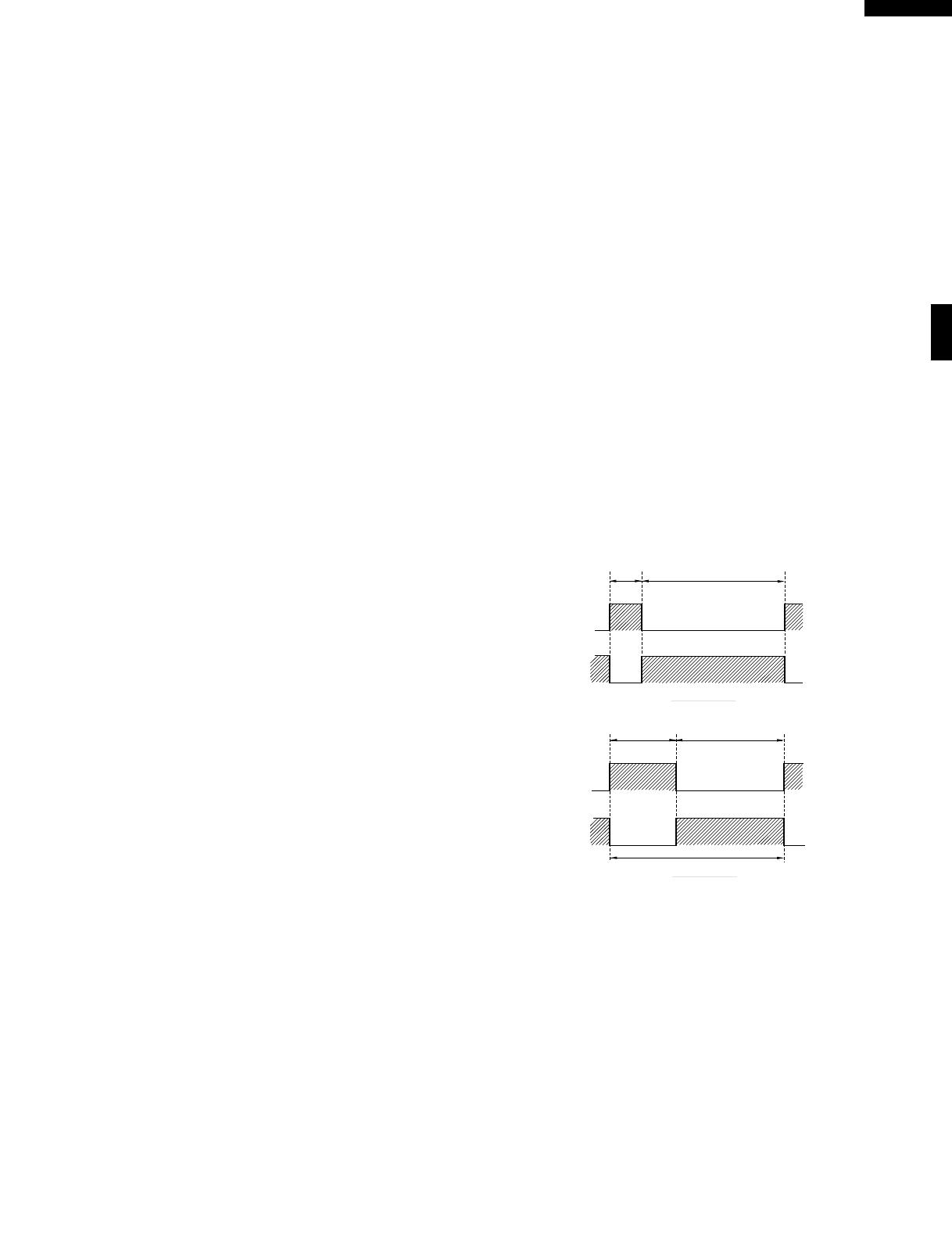
The relationship between the convection and microwave
power operations are as follows.
Note: The ON and OFF time ratio does not correspond
with the percentage of microwave power, because
approx. 2 seconds are needed for heating of the
magnetron filament.
Note: During alternate Microwave/Convection operation,
the convection heater is energized only if the cavity
temperature drops below the set temperature.
SENSOR COOKING CONDITION
Using the SENSOR COOK function, the foods are cooked
without figuring time, power level or quantity. When the oven
senses enough steam from the food, it relays the informa-
tion to its microprocessor which will calculate the remaining
cooking time and power level needed for best results. When
the food is cooked, water vapor is developed. The sensor
“senses” the vapor and its resistance increases gradually.
When the resistance reaches the value set according to the
menu, supplementary cooking is started.
The time of supplementary cooking is determined by experi-
ment with each food category and inputted into the LSI.
12 SEC. 20 SEC.
32 SEC.
LOW MIX
BAKE
HIGH MIX
ROAST
MICROWAVE POWER
= APPROX. 30%
CONVECTION
TEMPERATUE
= 300˚F
MICROWAVE POWER
= APPROX. 10%
CONVECTION
TEMPERATUE
= 350˚F (180˚C)
26 SEC.6 SEC.
ON
ON
OFF
OFF
OFF
ON
(MICRO.)
(CONVEC.)
(MICRO.)
(CONVEC.)
8
R-930CS
CONVECTION
MOTOR
THERMISTOR
Sensing 
Voltage
ON
OFF
ON
OFF
ON
OFF
0 2 24 30 64 (sec.)
3 sec.
Sensing the voltage across the temperature measurement circuit.
6 sec.
3
32 (sec.)
An example of how sensor works:
1. Potatoes at room temperature.
Vapor is emitted very slowly.
2. Heat potatoes. Moisture and
humidity is emitted rapidly.
You can smell the aroma as it
cooks.
3. Sensor detects moisture and
humidity and calculates
cooking time and variable
power.
Cooking Sequence.
1. Touch SENSOR COOK pad.
NOTE: The oven should not be operated on SENSOR
COOK immediately after plugging in the unit. Wait
two minutes before cooking on SENSOR COOK.
2. Select desired Sensor setting.
3. Touch START pad.
The coil of shut-off relay (RY1, RY6) is energized, the
oven lamp and cooling fan motor are turned on, but the
power transformer is not turned on.
4. After about 16 seconds, the cook relay (RY-2) is
energized. The power transformer is turned on,
microwave energy is produced and first stage is started.
The 16 seconds is the cooling time required to remove
any vapor from the oven cavity and sensor.
NOTE: During this first stage, do not open the door or touch
STOP/CLEAR pad.
5. When the sensor detects the vapor emitted from the
food, the display switches over to the remaining cooking
time and the timer counts down to zero. At this time, the
door may be opened to stir food, turn it or season, etc.
6. When the timer reaches zero, an audible signal sounds.
The shut-off relay and cook relay are de-energized and
the power transformer, oven lamp, etc. are turned off.
7. Opening the door or touching the STOP/CLEAR pad, the
time of day will reappear on the display and the oven will
revert to an OFF condition.
COMPU BROIL/ COMPU ROAST/ COMPU BAKE
COMPU BROIL/ ROAST/ BAKE will automatically compute
the oven temperature, microwave power and cooking time for
baking, roasting and broiling. Set the desired program by
touching the COMPU BROIL/ ROAST/ BAKE pad, and number
pad. Enter the weight by touching the Number pads. When the
START pad is touched, the following operations occur:
1. The COOK indicator will light and the Convection Fan
Symbol will rotate.
2. The cooking time will appear on the display and start
counting down to zero. The cooking time is adjusted
automatically according to the weight of the food.
3. The shut-off relays (RY1, RY5 and RY6) are energized,
turning on the oven lamp, turntable motor, cooling fan
motor and convection motor. The power supply voltage
is applied to the heating element.
4. Now, the oven is in the convection cooking mode.
5. When the oven temperature has reached the programmed
convection temperature, the oven goes into the
programmed cooking mode.
6. At the end of the COMPU BROIL/ ROAST/ BAKE cycle,
the damper is returned to the open position and the oven
will go to the off condition. The cooling fan will remain on
until the oven has cooled.
COMPU DEFROST COOKING
The COMPU DEFROST key is a special function key to
defrost meats and poultry faster and better. COMPU DE-
FROST automatically defrosts roast beef, etc.. When the
COMPU DEFROST is selected and the food weight is
entered by using the COMPU DEFROST pad, the oven will
cook according to the special cooking sequence.
FIRE SENSING FEATURE (MICROWAVE MODE)
This model incorporates a sensing feature which will stop
the oven's operation if there is a fire in the oven cavity during
microwave cooking. This is accomplished by the LSI repeat-
edly measuring the voltage across the temperature meas-
urement circuit (thermistor) during it's 32-seconds time
base comparing the obtained voltage measurements. If the
most recent voltage measured is 300mV greater than the
previous voltage measured, the LSI judges it as a fire in the
oven cavity and switches off the relays to the power trans-
former, fan motor and convection motor. The LSI also stops
counting down and closes the damper door so that no fresh
air will enter the oven cavity. Please refer to the following
section for a more detailed description.
Operation
Please refer to the timing diagrams below.
1. The thermistor operates within a 32-seconds time base
and it is energized for three (3) seconds and off for 29
seconds. Two (2) seconds after the thermistor is
energized, the voltage across the temperature
measurement circuit is sampled by the LSI and twenty
one (21) seconds after the thermistor is cut off the LSI
turns on the cooling fan for six (6) seconds.
2. The above procedure is repeated. If the difference between
the first voltage measured (in step 1) and the voltage
measured when the procedure is repeated (step 2) is
greater than 300mV the LSI makes the judgment that there
is a fire in the oven cavity and will switch off the relays to the
power transformer, fan motor and convection motor. The
LSI also stops counting down and closes the damper door
so that no fresh air will enter the oven cavity.
3. Once the fire sensor feature has shut the unit down, the
programmed cooking cycle may be resumed by pressing
the "START" pad or the unit may be reset by pressing the
"CLEAR" pad.
MICROWAVE
MICROWAVE
AH SENSOR
9
R-930CS
Figure O-2. Oven Schematic-Microwave Cooking Condition
SCHEMATIC
1. DOOR CLOSED.
2. COOKING TIME PROGRAMMED.
3. “START” PAD TOUCHED.
Figure O-1. Oven Schematic-OFF Condition
SCHEMATIC
NOTE: CONDITION OF OVEN
1. DOOR CLOSED.
2. CLOCK APPEARS ON DISPLAY.
SCHEMATIC DIAGRAM
IMPORTANT:
During sensor cooking operation, the fire sensing op-
eration sequence will not begin until the AH sensor has
detected vapors and initiated a sensor cooking cycle.
This is because the operation of the convection fan
would interfere with the AH sensor's vapor detection.
CONV.
THERMAL
CUT-OUT
MONITOR SWITCH
OVEN LAMP
FAN MOTOR
A-5
A-3
A-1
E-6
CONTROL UNIT
DAMPER
SWITCH
THER-
MISTOR
DOOR
SENSING
SWITCH
AH SENSOR
DAMPER MOTOR
CONVECTION MOTOR
TURNTABLE MOTOR
HEATIMG ELEMENT
MAGNETRON
POWER 
TRANSFORMER
H.V. RECTIFIER
CAPACITOR
0.94µ
RY4
RY5
RY6
RY1
SECONDARY
INTERLOCK
SWITCH
120V
60Hz
TTM
FM
COM.
(RY1)
E-5E-4E-3E-2E-1F-3F-2F-1
RY3
RY2
PRIMARY 
INTERLOCK
RELAY
N.O.
(RY1)
COM.
(RY3)
COM.
(RY2)
N.O.
(RY2)
N.O.
(RY3)
A-9
A-7
CM
DM
OL
MAGNETRON 
TEMPERATURE
FUSE
FUSE
RY2
10
R-930CS
DESCRIPTION AND FUNCTION OF COMPONENTS
SCHEMATIC
1. DOOR CLOSED.
2. CONVECTION PAD TOUCHED.
3. DESIRED TEMP. TOUCHED.
4. COOKING TIME PROGRAMMED.
5. “START” PAD TOUCHED.
SCHEMATIC
1. DOOR CLOSED.
2. MIX COOKING PAD TOUCHED.
3. COOKING TIME PROGRAMMED.
4. “START” PAD TOUCHED.
5. RY2 AND RY3 WILL ALTERNATELY CLOSE.
DURING COOK CYCLE.
Figure O-4. Oven Schematic-Convection Cooking Condition
Figure O-3. Oven Schematic-Automatic Mix Cooking Condition
CONV.
THERMAL
CUT-OUT
MONITOR SWITCH
OVEN LAMP
FAN MOTOR
A-5
A-3
A-1
E-6
CONTROL UNIT
DAMPER
SWITCH
THER-
MISTOR
DOOR
SENSING
SWITCH
AH SENSOR
DAMPER MOTOR
CONVECTION MOTOR
TURNTABLE MOTOR
HEATIMG ELEMENT
MAGNETRON
POWER 
TRANSFORMER
H.V. RECTIFIER
CAPACITOR
0.94µ
RY4
RY5
RY6
RY1
SECONDARY
INTERLOCK
SWITCH
120V
60Hz
TTM
FM
COM.
(RY1)
E-5E-4E-3E-2E-1F-3F-2F-1
RY3
RY2
PRIMARY 
INTERLOCK
RELAY
N.O.
(RY1)
COM.
(RY3)
COM.
(RY2)
N.O.
(RY2)
N.O.
(RY3)
A-9
A-7
CM
DM
OL
MAGNETRON 
TEMPERATURE
FUSE
FUSE
RY2
DOOR SENSING AND SECONDARY INTERLOCK
SWITCHES
The door sensing switch in the primary interlock system is
mounted in the upper position on the latch hook, the second-
ary interlock switch is mounted in the lower position on the
latch hook. They are activated by the latch heads on the door.
When the door is opened, the switches interrupt the circuit to
all components. A cook cycle cannot take place until the door
11
R-930CS
condition develops in the magnetron due to cooling fan
failure, obstructed air guide, dirty or blocked air intake, etc.
Under normal operation, the temperature fuse remains
closed. However, when abnormally high temperatures are
reached within the magnetron, the temperature fuse will
open at 302˚F(150˚C) causing the oven to shut down.
CONV. THERMAL CUT-OUT
The thermal cut-out located on the left side of the thermal
protection plate (left) is designed to prevent damage to the
heater unit if an over heated condition develops in the heat-
ing unit due to convection fan failure, thermistor failure,
obstructed air ducts, dirty or blocked air intake, etc. Under
normal operation, the thermal cut-out remains closed. How-
ever, when abnormally high temperatures are reached within
the heater unit, the thermal cut-out will open at 302˚F(150˚C)
causing the oven to shut down. When the thermal cut-out has
cooled, the thermal cut-out closes at 266˚F(130˚C).
HEATING ELEMENT
The heating element is located at the left side of the oven
cavity. It is intended to heat air driven by the convection fan.
The heated air is kept in the oven and force-circulated and
reheated by the heating element.
CONVECTION COOKING SYSTEM
This oven is designed with a hot air heating system where food
is not directly heated by the heating element, but is heated by
forced circulation of the hot air produced by the heating
element. The air heated by the heating element is circulated
through the convection passage provided on the outer casing
of the oven cavity by means of the convection fan which is
driven by the convection motor. It then enters the inside of the
oven through the vent holes provided on the left side of the
oven. Next, the hot air heats the food on the turntable and
leaves the oven cavity through the vent in the center of the
oven cavity left side wall. Without leaving the oven, this hot air
is reheated by the heating element, passes through the
convection passage and enters the inside of the oven cavity
again, in a continuing cycle. In this way, the hot air circulates
inside the oven cavity to raise its temperature and, at the same
time, comes into contact with the food being cooked. When the
temperature inside the oven cavity reaches the selected
temperature, the heating element is de-energized. When the
temperature inside the oven cavity drops below the selected
temperature, the heating element is energized again. In this
way, the inside of the oven cavity is maintained at approxi-
mately the selected temperature. When the convection time
reaches 0, the heating element is de-energized and the
convection fan stops operating and the oven shuts off.
DAMPER OPEN-CLOSE MECHANISM
Usually, the damper is in the open position except during
convection cooking. Damper position is set automatically
by damper motor, damper switch, motor cam and damper
shaft. These components are operated by a signal that
judges if microwave cooking or convection cooking opera-
tion is selected by the control unit.
Microwave Cooking:
Damper is in the open position, because a portion of cooling
is firmly closed thereby activating both interlock switches. The
primary interlock system consists of the door sensing switch
and primary interlock relay located on the control circuit board.
Figure D-1. Door sensing switch, monitor switch and
secondary interlock switches
MONITOR SWITCH
The monitor switch is mounted on the middle position of latch
hook. It is activated (the contacts opened) by the lower latch
head while the door is closed. The switch is intended to render
the oven inoperative by means of blowing the monitor fuse
when the contacts of the primary interlock relay and second-
ary interlock switch fail to open when the door is opened.
Functions:
1. When the door is opened, the monitor switch contact
close (to the ON condition) due to their being normally
closed. At this time the door sensing and secondary
interlock switches are in the OFF condition (contacts
open) due to their being normally open contact switches.
2. As the door goes to a closed position, the monitor switch
contacts are first opened and then the door sensing switch
and the secondary interlock switch contacts close. (On
opening the door, each of these switches operate inversely.)
3. If the door is opened, and the primary interlock relay and
secondary interlock switch contacts fail to open, the
monitor fuse blows simultaneously with closing of the
monitor switch contacts.
CAUTION: BEFORE REPLACING A BLOWN MONITOR
FUSE TEST THE DOOR SENSING SWITCH,
PRIMARY INTERLOCK RELAY, SECONDARY
INTERLOCK SWITCH AND MONITOR
SWITCH FOR PROPER OPERATION. (RE-
FER TO CHAPTER “TEST PROCEDURE”).
NOTE: MONITOR FUSE AND MONITOR SWITCH ARE
REPLACED AS AN ASSEMBLY.
THERMISTOR
The thermistor is a negative temperature coefficient type.
The temperature in the oven cavity is detected through the
resistance of the thermistor, and then the control unit
causes the heater relay to operate, thus the current to the
heating element is turned ON/OFF.
MAGNETRON TEMPERATURE FUSE.
The temperature fuse located on the waveguide is designed
to prevent damage to the magnetron if an over heated
LATCH HOOK
DOOR SENSING
SWITCH
MONITOR SWITCH
SECONDARY
INTERLOCK SWITCH
SWITCH LEVER
OPEN LEVER
DOOR OPEN 
BUTTON
MONITOR FUSE
LATCH 
HEADS
DOOR OPEN 
BUTTON
12
R-930CS
air is channelled through the cavity to remove steam and
vapors given off from the heating foods. It is then exhausted
at the top of the oven cavity into a condensation compartment.
Convection Cooking:
Damper is in the closed position, so that no hot air will be
allowed to leak out the oven cavity.
Damper Operation
1. When power supply cord is plugged in:
1-1. When power supply cord is plugged in, a signal is
sensed in the control unit, and operates shut-off
relay (RY4).
1-2. Contacts of shut-off relay (RY4) close, the damper
motor is energized, opening the damper door.
1-3. When the damper is moved to the open position by
the damper cam the damper switch is closed (ON
position).
1-4. The signal from damper switch is re-sensed in the
control unit and shut-off relay (RY4) is turned off.
1-5. The 120 volts A.C. to the damper motor is removed
and the motor turns off.
2. When oven is microwave cooking:
Damper is in the open position.
3. When oven is convection cooking:
3-1. Damper motor is energized by touching the
convection, temperature and START pads.
3-2. When damper is in the closed position (damper
switch is OFF), its signal is sensed by the control
unit, and shut-off relay (RY4) is de-energized.
3-3. The damper is held in the closed position during the
convection cooking operation.
3-4. At the end of the convection cooking, shut-off relay
(RY4) is energized, and the damper is returned to
the open position.
NOTE: If the damper door is not in the proper position,
closed during convection or open during microwave,
the control unit will stop oven operation after 1
minute.
Figure D-2. Damper Mechanism
DAMPER DUCT
DAMPER
DAMPER CAM
DAMPER MOTOR
DAMPER SWITCH
DAMPER SHAFT
TROUBLESHOOTING GUIDE
Never touch any part in the circuit with your hand or an uninsulated tool while the power supply is connected.
When troubleshooting the microwave oven, it is helpful to follow the Sequence of Operation in performing the checks. Many
of the possible causes of trouble will require that a specific test be performed. These tests are given a procedure letter which
will be found in the "Test Procedure "section.
IMPORTANT: If the oven becomes inoperative because of a blown monitor fuse, check the monitor switch, relay (RY1)
primary interlock relay (RY2), door sensing switch and secondary interlock switch before replacing the
monitor fuse. If the monitor fuse is replaced, the monitor switch must also be replaced. Use part FFS-
BA012WRK0 as an assembly.
IMPORTANT: Whenever troubleshooting is performed with the power supply cord disconnected. It may in, some cases,
be necessary to connect the power supply cord after the outer case has been removed, in this event,
1. Disconnect the power supply cord, and then remove outer case.
2. Open the door and block it open.
3. Discharge high voltage capacitor.
4. Disconnect the leads to the primary of the power transformer.
5. Ensure that the leads remain isolated from other components and oven chassis by using insulation tape.
6. After that procedure, reconnect the power supply cord.
When the testing is completed
1. Disconnect the power supply cord, and then remove outer case.
2. Open the door and block it open.
3. Discharge high voltage capacitor.
4. Reconnect all leads removed from components during testing.
5. Reinstall the outer case (cabinet).
6. Reconnect the power supply cord after the outer case is installed.
7. Run the oven and check all functions.
13
R-930CS
A MAGNETRON
B POWER TRANSFORMER
C H.V. RECTIFIER ASSEMBLY
D HIGH VOLTAGE CAPACITOR
E SECONDARY INTERLOCK SWITCH
F PRIMARY INTERLOCK SYSTEM
G MONITOR SWITCH
H MONITOR FUSE
I MAGNETRON TEMPERATURE FUSE
J CONV. THERMAL CUT-OUT
K CONVECTION HEATER
L THERMISTOR
M DAMPER MOTOR
N DAMPER SWITCH
P TOUCH CONTROL PANEL
Q KEY UNIT
R RELAY RY-1
R RELAY RY-2
R RELAY RY-3
R RELAY RY-4
R RELAY RY-5
R RELAY RY-6
S COMP. DEFROST
T FOIL PATERN ON PWB.
U AH SENSOR
Replace OVEN LAMP OR SOCKET
Replace FAN MOTOR
Replace TURNTABLE MOTOR
Replace CONVECTION MOTOR
Check LOOSE WIRING
Check SHORTED IN POWER CORD
Check NO POWER AT OUTLET
Check LOW VOLTAGE
POSSIBLE CAUSE
AND
DEFECTIVE PARTS
TEST PROCEDURE
CONDITION
COOKING CONDITION (MICROWAVE)
(CONVECTION)
(SENSOR
COOKING)
OFF CONDITION
Home fuse blows when power cord is plugged into wall receptacle.
Monitor fuse blows when power cord is plugged into wall receptacle
88:88 does not appear in display when power cord is first plugged into
wall receptacle.
Display does not operate properly when STOP/CLEAR pad is touched.
(The time of day should appear on the display with beep sound.)
Oven lamp does not light with door opened.
Oven lamp does not light in cook cycle. (It light when door is opened).
Cooking cycle runs 1 minute then shuts down.
Oven lamp light, but turntable motor does not operate.
Turntable motor operates normally but cooling fan motor does not
operate.
Oven does not go into a cook cycle, when START pad is touched.
Low or no power is produced during microwave cooking (The food is
heated incompletely or not heated at all)
Extremely uneven heating is produced in oven load (food).
Function of variable cooking does not operate properly except HIGH
power.
Function of COMPU DEFROST does not operate properly.
CONV indicator lights, but oven does not go into cook cycle when
START pad is touched.
CONV indicator lights, but heating element does not heat.
Temperature in the oven cavity is lower or higher than preset.
Cooling fan motor runs intermittently or all the time.
Convection cycle runs 4 minutes and 15 seconds then shuts down.
Oven in the sensor cooking condition but AH sensor does not end or AH
sensor turns off about max. 30 min. after start.
PROBLEM
14
R-930CS
TEST PROCEDURES
PROCEDURE
LETTER
COMPONENT TEST
1. Disconnect the power supply cord, and then remove outer case.
2. Open the door and block it open.
3. Discharge high voltage capacitor.
4. To test for an open filament, isolate the magnetron from the high voltage circuit. A continuity check
across the magnetron filament leads should indicate less than 1 ohm.
5. To test for a shorted magnetron, connect the ohmmeter leads between the magnetron filament leads
and chassis ground. This test should indicate an infinite resistance. If there is little or no resistance
the magnetron is grounded and must be replaced.
6. Reconnect all leads removed from components during testing.
7. Reinstall the outer case (cabinet).
8. Reconnect the power supply cord after the outer case is installed.
9. Run the oven and check all functions.
MICROWAVE OUTPUT POWER
The following test procedure should be carried out with the microwave oven in a fully assembled
condition (outer case fitted).
HIGH VOLTAGES ARE PRESENT DURING THE COOK CYCLE, SO EXTREME CAUTION SHOULD
BE OBSERVED.
Power output of the magnetron can be measured by performing a water temperature rise test. This test
should only be used if above tests do not indicate a faulty magnetron and there is no defect in the following
components or wiring: silicon rectifier, high voltage capacitor and power transformer. This test will require
a 16 ounce (453cc) measuring cup and an accurate mercury thermometer or thermocouple type
temperature tester. For accurate results, the following procedure must be followed carefully:
1. Fill the measuring cup with 16 oz. (453cc) of tap water and measure the temperature of the water with
a thermometer or thermocouple temperature tester. Stir the thermometer or thermocouple through
the water until the temperature stabilizes. Record the temperature of the water.
2. Place the cup of water in the oven. Operate oven at POWER 10(HIGH) selecting more than 60
seconds cook time. Allow the water to heat for 60 seconds, measuring with a stop watch, second hand
of a watch or the digital read-out countdown.
3. Remove the cup from the oven and again measure the temperature, making sure to stir the
thermometer or thermocouple through the water until the maximum temperature is recorded.
4. Subtract the cold water temperature from the hot water temperature. The normal result should be 22
to 43˚F(12.2 to 23.8˚C) rise in temperature. If the water temperatures are accurately measured and
tested for the required time period the test results will indicate if the magnetron tube has low power
output (low rise in water temperature) which would extend cooking time or high power output (high
rise in water temperature) which would reduce cooking time. Because cooking time can be adjusted
to compensate for power output, the magnetron tube assembly should be replaced only if the water
temperature rise test indicates a power output well beyond the normal limits. The test is only accurate
if the power supply line voltage is 120 volts and the oven cavity is clean.
A MAGNETRON ASSEMBLY TEST
B POWER TRANSFORMER TEST
1. Disconnect the power supply cord, and then remove outer case.
2. Open the door and block it open.
3. Discharge high voltage capacitor.
4. Disconnect the primary input terminals and measure the resistance of the transformer with an
ohmmeter. Check for continuity of the coils with an ohmmeter. On the R x 1 scale, the resistance of
the primary coil should be less than 1 ohm and the resistance of the high voltage coil should be
approximately 81.7 ohms; the resistance of the filament coil should be less than 1 ohm.
5. Reconnect all leads removed from components during testing.
6. Reinstall the outer case (cabinet).
7. Reconnect the power supply cord after the outer case is installed.
8. Run the oven and check all functions.
15
R-930CS
C HIGH VOLTAGE RECTIFIER TEST
1. Disconnect the power supply cord, and then remove outer case.
2. Open the door and block it open.
3. Discharge high voltage capacitor.
4. Isolate the rectifier from the circuit. Using the highest ohm scale of the meter, read the resistance
across the terminals and observe, reverse the leads to the rectifier terminals and observe meter
reading. If a short is indicated in both directions, or if an infinite resistance is read in both directions,
the rectifier is probably defective and should be replaced.
5. Reconnect all leads removed from components during testing.
6. Reinstall the outer case (cabinet).
7. Reconnect the power supply cord after the outer case is installed.
8. Run the oven and check all functions.
NOTE: Be sure to use an ohmmeter that will supply a forward bias voltage of more than 6.3 volts.
E SECONDARY INTERLOCK SWITCH TEST
1. Disconnect the power supply cord, and then remove outer case.
2. Open the door and block it open.
3. Discharge high voltage capacitor.
4. Isolate the switch and connect the ohmmeter to the common (COM.) and normally open (NO) terminal
of the switch. The meter should indicate an open circuit with the door open and a closed circuit with
the door closed. If improper operation is indicated, replace the secondary interlock switch.
5. Reconnect all leads removed from components during testing.
6. Reinstall the outer case (cabinet).
7. Reconnect the power supply cord after the outer case is installed.
8. Run the oven and check all functions.
F PRIMARY INTERLOCK SYSTEM TEST
DOOR SENSING SWITCH
1. Disconnect the power supply cord, and then remove outer case.
2. Open the door and block it open.
3. Discharge high voltage capacitor.
4. Isolate the switch and connect the ohmmeter to the common (COM.) and normally open (NO) terminal
of the switch. The meter should indicate an open circuit with the door open and a closed circuit with
the door closed. If improper operation is indicated, replace the door sensing switch.
TEST PROCEDURES
PROCEDURE
LETTER
COMPONENT TEST
D HIGH VOLTAGE CAPACITOR TEST
1. Disconnect the power supply cord, and then remove outer case.
2. Open the door and block it open.
3. Discharge high voltage capacitor.
4. If the capacitor is open, no high voltage will be available to the magnetron. Disconnect input leads
and check for short or open between the terminals using an ohmmeter.
Checking with a high ohm scale, if the high voltage capacitor is normal, the meter will indicate
continuity for a short time and should indicate an open circuit once the capacitor is charged. If the
above is not the case, check the capacitor with an ohmmeter to see if it is shorted between either of
the terminals and case. If it is shorted, replace the capacitor.
5. Reconnect all leads removed from components during testing.
6. Reinstall the outer case (cabinet).
7. Reconnect the power supply cord after the outer case is installed.
8. Run the oven and check all functions.
(HIGH VOLTAGES ARE PRESENT AT THE HIGH VOLTAGE TERMINAL, SO DO NOT ATTEMPT TO
MEASURE THE FILAMENT AND HIGH VOLTAGE.)
16
R-930CS
TEST PROCEDURES
PROCEDURE
LETTER
COMPONENT TEST
5. Reconnect all leads removed from components during testing.
6. Reinstall the outer case (cabinet).
7. Reconnect the power supply cord after the outer case is installed.
8. Run the oven and check all functions.
NOTE: If the door sensing switch contacts fail in the open position and the door is closed, the turntable
motor and oven light will be activated by RY1.
PRIMARY INTERLOCK RELAY (RY2)
1. Disconnect the power supply cord, and then remove outer case.
2. Open the door and block it open.
3. Discharge high voltage capacitor.
4. Disconnect two (2) wire leads from the male tab terminals of the Primary Interlock Relay (RY2). Check
the state of the relay contacts using a ohmmeter. The relay contacts should be open. If the relay
contacts are closed, replace the circuit board entirely or the relay itself.
5. Reconnect all leads removed from components during testing.
6. Reinstall the outer case (cabinet).
7. Reconnect the power supply cord after the outer case is installed.
8. Run the oven and check all functions.
G MONITOR SWITCH
1. Disconnect the power supply cord, and then remove outer case.
2. Open the door and block it open.
3. Discharge high voltage capacitor.
4. Before performing this test, make sure that the secondary interlock switch and the primary interlock
relay are operating properly, according to the above Switch Test Procedure. Disconnect the wire
lead from the monitor switch (COM) terminal. Check the monitor switch operation by using the
ohmmeter as follows. When the door is open, the meter should indicate a closed circuit. When the
monitor switch actuator is pushed by a screw driver through the lower latch hole on the front plate
of the oven cavity with the door opened (in this condition the plunger of the monitor switch is pushed
in), the meter should indicate an open circuit. If improper operation is indicated, the switch may be
defective. After testing the monitor switch, reconnect the wire lead to the monitor switch (COM)
terminal and check the continuity of
the monitor circuit.
5. Reconnect all leads removed from
components during testing.
6. Reinstall the outer case (cabinet).
7. Reconnect the power supply cord
after the outer case is installed.
8. Run the oven and check all functions.
SCREW DRIVER
MONITOR SWITCH
OHMMETER
SECONDARY
INTERLOCK
SWITCH
COM.
N.C.
H BLOWN MONITOR FUSE
1. Disconnect the power supply cord, and then remove outer case.
2. Open the door and block it open.
3. Discharge high voltage capacitor.
4. If the monitor fuse is blown when the door is opened, check the primary interlock relay, secondary
interlock switch and monitor switch according to the "TEST PROCEDURE" for those switches before
replacing the blown monitor fuse.
CAUTION: BEFORE REPLACING A BLOWN MONITOR FUSE, TEST THE PRIMARY INTERLOCK
RELAY, SECONDARY INTERLOCK SWITCH, DOOR SENSING SWITCH AND MONITOR
SWITCH FOR PROPER OPERATION.
If the monitor fuse is blown by improper switch operation, the monitor fuse and monitor switch must be
replaced with "monitor fuse and monitor switch assembly" part number FFS-BA012WRK0, even if the
monitor switch operates normally. The monitor fuse and monitor switch assembly is comprised of a 20
ampere fuse and switch.
17
R-930CS
TEST PROCEDURES
PROCEDURE
LETTER
COMPONENT TEST
I MAGNETRON TEMPERATURE FUSE TEST
1. Disconnect the power supply cord, and then remove outer case.
2. Open the door and block it open.
3. Discharge high voltage capacitor.
4. A continuity check across the temperature fuse terminals should indicate a closed circuit unless the
temperature of the magnetron reaches approximately 302˚F(150˚C). An open temperature fuse
indicates overheating of the magnetron. Check for restricted air flow to the magnetron, especially the
cooling duct and cooling fan.
5. Reconnect all leads removed from components during testing.
6. Reinstall the outer case (cabinet).
7. Reconnect the power supply cord after the outer case is installed.
8. Run the oven and check all functions.
CAUTION: IF THE TEMPERATURE FUSE INDICATES AN OPEN CIRCUIT AT ROOM TEMPERA-
TURE, REPLACE TEMPERATURE FUSE.
1. Disconnect the power supply cord, and then remove outer case.
2. Open the door and block it open.
3. Discharge high voltage capacitor.
4. A continuity check across the thermal cut-out terminals should indicate a closed circuit unless the
temperature of the thermal cut-out reaches approximately 302˚F(150˚C). The thermal cut-out resets
automatically at approximately 266˚F(130˚C). If thermal cut-out has opened under normal condition,
replace the same item as in the parts list.
An open thermal cut-out indicates overheating of the heater unit. Check for restricted air flow to the
heater unit through the vent holes of the oven cavity, especially the heater duct and convection fan.
5. Reconnect all leads removed from components during testing.
6. Reinstall the outer case (cabinet).
7. Reconnect the power supply cord after the outer case is installed.
8. Run the oven and check all functions.
CAUTION: IF THE THERMAL CUT-OUT INDICATES AN OPEN CIRCUIT AT ROOM TEMPERATURE,
REPLACE THERMAL CUT-OUT.
K HEATING ELEMENT TEST
1. Disconnect the power supply cord, and then remove outer case.
2. Open the door and block it open.
3. Discharge high voltage capacitor.
4. Make sure the heating element is fully cooled and test as follows;
a. Disconnect wire leads from the heating element and measure the resistance with an ohmmeter.
On the R x 1 scale, the resistance between the heating element terminals should be approximately
10.2.
b. Disconnect wire leads from the heating element and measure the insulation resistance with 500V
- 100M insulation resistance meter. The insulation resistance between heating element terminal
and cavity should be more than 0.5M.
5. If the meter does not indicate above resistance, replace the thermistor
6. Reconnect all leads removed from components during testing.
7. Reinstall the outer case (cabinet).
8. Reconnect the power supply cord after the outer case is installed.
9. Run the oven and check all functions.
5. Reconnect all leads removed from components during testing.
6. Reinstall the outer case (cabinet).
7. Reconnect the power supply cord after the outer case is installed.
8. Run the oven and check all functions.
J CONV. THERMAL CUT-OUT TEST
18
R-930CS
1. Disconnect the power supply cord, and then remove outer case.
2. Open the door and block it open.
3. Discharge high voltage capacitor.
4. Disconnect the leads to the primary of the power transformer.
5. Ensure that the leads remain isolated from other components and oven chassis by using insulation tape.
6. Disconnect the wire leads from the switch terminals and connect ohmmeter leads to the common
(COM.) and normally open (N.O.) terminals of the switch.
6-1. When switch actuator is pushed by the damper motor cam, the meter should be indicated a closed
circuit.
6-2. When power cord is plugged into the wall receptacle, the damper motor operates and damper cam will
start to rotate. When the switch actuator is released, the meter should be indicated an open circuit.
7. If improper operation is indicated, replace the damper switch.
8. Disconnect the power supply cord, and then remove outer case.
N DAMPER SWITCH TEST
TEST PROCEDURES
PROCEDURE
LETTER
COMPONENT TEST
1. Disconnect the power supply cord, and then remove outer case.
2. Open the door and block it open.
3. Discharge high voltage capacitor.
4. Disconnect connector-E from the control unit. Measure the resistance of the thermistor with an
ohmmeter. Connect the ohmmeter leads to Pin No’s E-3 and E-4.
Room Temperature Resistance
68˚F(20˚C) - 86˚F(30˚C) Approx. 350k - 155K
5. If the meter does not indicate above resistance, replace the thermistor.
6. Reconnect all leads removed from components during testing.
7. Reinstall the outer case (cabinet).
8. Reconnect the power supply cord after the outer case is installed.
9. Run the oven and check all functions.
L THERMISTOR TEST
M DAMPER MOTOR TEST
When the power cord is plugged into the wall receptacle and 120 volts A.C. is supplied to the damper
motor, the motor operates until the damper is opened and the damper switch closes. Then the damper
motor stops operation.
If the damper motor does not operate, check for A.C. voltage with a voltmeter at the motor.
1. Disconnect the power supply cord, and then remove outer case.
2. Open the door and block it open.
3. Discharge high voltage capacitor.
4. Disconnect the leads to the primary of the power transformer.
5. Ensure that the leads remain isolated from other components and oven chassis by using insulation
tape.
6. Disconnect the wire leads of motor and connect the meter leads to the wire leads of main wire harness.
7. Re-connect the power cord into the wall receptacle.
8. If 120 volts A.C. is indicated at the wire leads, replace the motor and if 120 volts A.C. is not indicated,
check the wire harness and control unit.
9. Disconnect the power supply cord, and then remove outer case.
10.Open the door and block it open.
11.Discharge high voltage capacitor.
12.Reconnect all leads removed from components during testing.
13.Re-install the outer case (cabinet).
14.Reconnect the power supply cord after the outer case is installed.
15.Run the oven and check all functions.
  • Page 1 1
  • Page 2 2
  • Page 3 3
  • Page 4 4
  • Page 5 5
  • Page 6 6
  • Page 7 7
  • Page 8 8
  • Page 9 9
  • Page 10 10
  • Page 11 11
  • Page 12 12
  • Page 13 13
  • Page 14 14
  • Page 15 15
  • Page 16 16
  • Page 17 17
  • Page 18 18
  • Page 19 19
  • Page 20 20
  • Page 21 21
  • Page 22 22
  • Page 23 23
  • Page 24 24
  • Page 25 25
  • Page 26 26
  • Page 27 27
  • Page 28 28
  • Page 29 29
  • Page 30 30
  • Page 31 31
  • Page 32 32
  • Page 33 33
  • Page 34 34
  • Page 35 35
  • Page 36 36
  • Page 37 37
  • Page 38 38
  • Page 39 39
  • Page 40 40
  • Page 41 41
  • Page 42 42
  • Page 43 43
  • Page 44 44
  • Page 45 45
  • Page 46 46
  • Page 47 47
  • Page 48 48
  • Page 49 49

Ariens 39428 User manual

Category
Microwaves
Type
User manual

Ask a question and I''ll find the answer in the document

Finding information in a document is now easier with AI