
Printed in the U. S. A.© Copyright 1997 R. L. Drake Co.
P/N: 3851295F-4-1997
TONE
H
VOLUME
TUNING
SW8 World Band
Shortwave Receiver
BAND
AGC S AM SYNC
METER
TIMER
+60
+40
+20
9
7
5
3
1
KHz
SW
M E M
SSB
5
BW
6
SCAN
MEM
LAMP
9
STORE
VFO
SKIP
CLEAR
BEEP
TIMER
CLOCK
AGC
8
AM
SYNC
4
DEL
0
ATT
7
BCB
1
AIR
2
SW
3
F
L
POWER
push
6.0
Owner's Manual
is a registered trademark of the R. L. Drake Company
®
®
SW8 World Band Shortwave Receiver
with Selectable Sideband Synchronous Detector
LSB
Downloaded by
Amateur Radio Directory
www.hamdirectory.info

Date: April 26/1996
Ref. No. 963732
Signature: ______________________
Name: P. Kraßowski Dipl.-Ing.
Declaration of Conformity
We, Manufacturer/Importer
(Full address)
R. L. Drake Company
230 Industrial Drive
Franklin, Ohio 45005 United States of America
declare that the product
(description of the apparatus, system, installation to which it refers)
SW8 World Band Shortwave Receiver
1295
is in conformity with
(reference to the specifications under which conformity is declared)
in accordance with 89/336/EEC-EMC Directive
Disturbances in supply systems caused
by household appliances and similar
electrical equipment "Harmonics"
Disturbances in supply systems caused
by household appliances and similar
electrical equipment "Voltage fluctuations"
Generic emission standard Part 1:
Residual, commercial and light industry
Generic immunity standard Part 1:
Residual, commercial and light industry
Generic emission standard
Part 2: Industrial environment
Generic immunity standard
Part 2: Industrial environment
Signalling on low-voltage electrical
Installations in the frequency range of 3kHz
to 148.5kHz
Part 1: General requirements, frequency
bands and electromagnetic disturbances
Immunity requirements for household
appliances tools and similar apparatus
EN 55011
EN 55013
EN 55014
EN 55015
EN 55020
EN 55022
DIN V VDE 0855
part 10
part 12
CE marking
EN 60065
EN 60555-2
EN 60555-3
EN 50081-1
EN 50082-1
EN 50081-2
EN 50082-2
EN 50065-1
EN55104
Limits and methods of measurement
of radio disturbance characteristics of
industrial, scientific and medical (ISM)
high frequency equipment
Limits and methods of measurement
of radio disturbance characteristics of
broadcast receivers and associated
equipment
Limits and methods of measurement
of radio disturbance characteristics of
household electrical appliances,
portable tools and similar electrical
apparatus
Limits and methods of measurement
of radio disturbance characteristics of
flourescent lamps and luminaries
immunity from radio interference of
broadcast receivers and associated
equipment
Limits and methods of measurement
of radio disturbance characteristics of
information technology equipment
Cabled distribution systems; Equipment
for receiving and/or distribution from
sound and television signals
Safety requirements for mains operated
electronic and related apparatus for
household and similar general use
(EC conformity marking)
The manufacturer/importer also declares the conformity of above mentioned product
with the actual required safety standards in accordance with LVD 73/23 EEC.
Manufacturer/Importer
Signature: ___________________
Name: Ronald E. Wysong____Date: January 01, 1997__
(Stamp)
®
EMC Tested by electronic GmbH

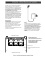
Important Safeguards i
TO REDUCE THE RISK OF FIRE OR ELECTRIC SHOCK, DO NOT EXPOSE THIS PRODUCT'S
AC ADAPTOR TO RAIN OR MOISTURE. DO NOT OPEN THE AC ADAPTOR CASE, REFER
SERVICING TO QUALIFIED PERSONNEL ONLY.
WARNING:
An appliance and cart combination should be moved
with care. Quick stops, excessive force and uneven
surfaces may cause the appliance and cart combina-
tion to overturn.
The lightning flash with arrow head symbol, within an
equilateral triangle, is intended to alert the user to the
presence of uninsulated "dangerous voltage" within
the product's enclosure that may be of sufficient
magnitude to constitute a risk of electric shock to
persons.
The exclamation point within an equilateral triangle is
intended to alert the user to the presence of impor-
tant operating and maintenance (servicing) instruc-
tions in the literature accompanying the appliance.
WARNING: TO PREVENT FIRE OR
ELECTRICAL SHOCK DO NOT
EXPOSE THIS PRODUCT'S AC ADAPTOR TO
RAIN OR MOISTURE
TO PREVENT ELECTRIC SHOCK, DO NOT USE THE AC ADAPTOR WITH AN EXTENSION CORD
RECEPTACLE OR OTHER OUTLET UNLESS THE BLADES OF THE AC ADAPTOR CAN BE FULLY
INSERTED TO PREVENT BLADE EXPOSURE.
POUR PREVENIR LES CHOCS ELECTRIQUES, NE PAS UTILISER CETTE FICHE POLARISEE
AVEC UN PROLONGATEUR, UNE PRISE DE COURANT OU UNE AUTRE SORTIE DE COUR-
ANT, SAUF SI LES LAMES PEUVENT ETRE INSEREES A FOND SANS EN LAISSER AUCUNE
PARTIE A DECOUVERT.
CAUTION:
ATTENTION:
¡CAUTION!
RISK OF ELECTRIC SHOCK
DO NOT OPEN
CAUTION: TO REDUCE THE RISK OF ELECTRIC
SHOCK,
DO NOT REMOVE COVER OF AC ADAPTOR
NO USER-SERVICABLE PARTS INSIDE
REFER SERVICING TO QUALIFIED PERSONNEL
1. Read Instructions—All the safety and operating instructions
should be read before the appliance is operated.
2. Retain Instructions—The safety and operating instructions
should be retained for future reference.
3. Heed Warnings—All warnings on the appliance should be
adhered to.
4. Follow Instructions—All operating and use instructions should
be followed.
5. Cleaning—Unplug this appliance from the wall outlet before
cleaning. Do not use liquid cleaners or aerosol cleansers. Use a
damp cloth for cleaning.
6. Do Not Use Attachments—not recommended by the manu-
facturer or they may cause hazards.
7. Water and Moisture—Do not use this product near water—for
example, near a bathtub, wash bowl, kitchen sink, laundry tub, in
a wet basement, or near a swimming pool—and the like.
8. Accessories—Do not place this product on an unstable cart,
stand, tripod, bracket, or table. The product may fall, causing
serious injury to a child or adult, and serious damage to the
appliance.
9. Ventilation—This product should never be placed near or over
a radiator or heat register. This product should not be placed in a
built-in installation such as a bookcase or rack unless proper
ventilation is provided or the manufacturer’s instructions have
been adhered to. Any slots or openings in the cabinet are provided
for ventilation.
To ensure reliable operation of the product and to protect it from
overheating, these openings must not be blocked or covered. The
openings should never be blocked by placing the product on a
bed, sofa, rug, or other similar surface. KEEP CURTAINS AND
OTHER FLAMMABLE MATERIALS OUT OF DIRECT CON-
TACT WITH THE AC ADAPTOR.
10. Power Sources—This product should be operated only from
the type of power source indicated on the marking label of the
supplied AC Adaptor. If you are not sure of the type of power
supplied to your home, consult your appliance dealer or local
power company.
11. Lightning—For added protection for this product during a
lightning storm, or when it is left unattended and unused for long
periods of time, unplug the AC adaptor from the wall outlet.
12. Power Lines—An outside antenna system should not be
located in the vicinity of overhead power lines, other electric light
or power circuits, where it can fall into such power lines or circuits.
When installing an outside antenna system, extreme care should
be taken to keep from touching such power lines or circuits as
contact with them may be fatal.
13. Overloading—Do not overload wall outlets and extension
cords as this can result in a risk of fire or electric shock.

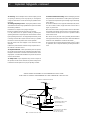
GROUND CLAMPS
ANTENNA
LEAD IN
WIRE
ELECTRIC
SERVICE
EQUIPMENT
GROUND CLAMP
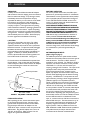
NEC - NATIONAL ELECTRIC CODE
EXAMPLE OF ANTENNA GROUNDING
POWER SERVICE GROUNDING
ELECTRODE SYSTEM
(NEC ART 250, PART H)
GROUNDING CONDUCTORS
(NEC SECTION 810-21)
ANTENNA
DISCHARGE UNIT
(NEC SECTION 810-20)
" INSTALL WIRING ACCORDING TO THE CANADIAN ELECTRICAL CODE"
"EFFECTUER LE CABLAGE CONFORMEMENT AU CODE CANADIEN DE L' ELECTRICITE"
ii Important Safeguards, continued
18. Outdoor Antenna Grounding—Before attempting to install
this product, be sure the antenna or cable system is grounded so
as to provide some protection against voltage surges and built-up
static charges.
a. Use No.10 AWG (5.3mm
2
) copper, No.8 AWG (8.4mm
2
) alumi-
num, No.17 AWG (1.0mm
2
) copper-clad steel or bronze wire or
larger, as ground wire.
b. Secure antenna lead-in and ground wires to house with stand-
off insulators spaced from 4 feet (1.22m) to 6 feet (1.83m) apart.
c. Mount antenna discharge unit as close as possible to where
lead-in enters house.
d. A driven rod may be used as the grounding electrode where
other types of electrode systems do not exist. Refer to the National
Electrical Code, ANSI/NFPA 70-1990 for information.
e. Use jumper wire not smaller than No.6 AWG 13.3mm
2
) copper
or equivalent, when a separate antenna grounding electrode is
used.
14. Servicing—Do not attempt to service the AC adaptor yourself
as opening or removing covers may expose you to dangerous
voltage or other hazards. Refer all servicing to qualified service
personnel.
15. Damage Requiring Service—Unplug this product from the
wall outlet and refer servicing to qualified service personnel under
the following conditions:
a. When the AC adaptor cord or plug is damaged.
b. If the AC adaptor has been exposed to rain or water.
c. If the product does not operate normally by following the
operating instructions. Adjust only those controls that are covered
by the operating instructions. An improper adjustment may result
in damage and will often require extensive work by a qualified
technician to restore the product to its normal operation.
d. If the product has been dropped or the cabinet has been
damaged.
e. When the product exhibits a distinct change in performance—
this indicates a need for service.
16. Replacement Parts—When replacement parts are required,
be sure the service technician has used replacement parts speci-
fied by the manufacturer or have the same characteristics as the
original parts. Unauthorized substitutes may result in fire, electric
shock or other hazards.
17. Safety Check—Upon completion of any service or repairs to
this product, ask the service technician to perform safety checks
to determine that the product is in proper operating condition.

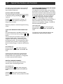
Thank you for purchasing a Drake SW8 World Band
Shortwave Receiver. This receiver has been designed
and manufactured to high quality standards, and will
provide reliable operation for many years.
Please carefully read the Owner's Manual in order to
take advantage of the many interesting features that
will provide enjoyable listening to radio broadcasts
around the world.
Important Safeguards
Table of Contents
Introduction - General Description
Introduction - Specifications
Optional Accessories
Introduction - Battery Operation and
Installation
Installation
Unpacking
Location
Adjusting Carrying Handle
Fixed Installation
Portable Operation
Antenna Requirements
Installation Diagram
Front Panel Description
Telescoping WHIP Antenna
Front Panel Display
Rear Panel Description
Aircraft Band Squelch
Master Power Switch
Getting Started
General Operating Information
Microprocessor Reset
Beep Tones
Direct Frequency Entry
Shortwave METER Band
Designator Entry
Frequency Resolution
Front Panel Lock (Unlock)
AM Synchronous Operation
SSB Operation
FM Operation
AGC Operation
i
iii
1
2
2
3
4
4
4
4
4
4
4
5
6
7
8
9
9
9
10
10
10
10
10
11
12
12
12
12
12
12
13
13
13
13
14
14
15
15
15
15
15
16
16
17
17
18
18
18
18
18
19
21
24
25
26
27
Memory Functions
Memory Location Programming
Recalling A Memory Location
Deleting A Memory Location
Scan Functions
Memory Channel Skip
Clock and Timer Functions
Time Display
Setting The 24 Hour Clocks
Timer Operation
Setting Timer On/Off Times
Example for Setting Timer
Enabling / Disabling Timer
Example for Setting Overlapping
Events
Example for Setting Events On Two
Different Memory Channels
Special Use Features and Functions
Lock All Entry to Keypad
10 kHz/9 kHz Broadcast Band Tuning
Step Size
Delete All Memory Channels
Automatic Bandwidth Setting with
Mode Selection Disable (Enable)
Quick Reference Guide
Memory Channel Log
Suggested References
Glossary of Terms
Troubleshooting
Service and Warranty
Table of Contents iii

iv

Introduction - General Description 1
The SW8 is a microprocessor controlled, synthesized,
world band receiver with continuous coverage capabil-
ity from 500 kHz through 30 MHz which includes the
AM broadcast and shortwave bands. Reception also
includes FM broadcast (87 - 108 MHz) and Aircraft
(118-137 MHz). The SW8 offers excellent sensitivity,
selectivity, dynamic range and features that permit easy
tuning of desired stations. Conveniently located front
panel controls allow for rapid operator programming
and ease of use. The unit can be operated from either
the supplied AC Adaptor or from six D cell batteries
(not supplied) for portable operation. A low battery
voltage indication is displayed when that condition
exists.
Three electronically switched IF filters are provided.
The front panel liquid crystal display provides feedback
of the current status of the receiver. The seven digit
frequency display provides resolution to 100 Hz
accuracy in the AM broadcast, Aircraft and Shortwave
bands. Resolution to 20 kHz is displayed in the FM
broadcast band mode. Backlighting of the display is
selectable by a front panel button. To prolong battery
life with internal battery operation, the backlighting
automatically turns off after a short delay following a
function change or retuning of the receiver.
Reception modes include Lower/Upper Sideband
(LSB), (USB), and AM in the Shortwave, AM broadcast
and Aircraft bands. For the Shortwave and AM
broadcast bands, a selectable synchronous detector
(SYNC) allows for enhanced reception by eliminating
or reducing distortion due to fading signals. During FM
broadcast use, stereo reception is available through the
use of headphones.
Other built-in reception aids include selectable slow or
fast AGC, RF attenuator for use in strong signal
handling conditions and TONE control.
Two independent, real time clocks provide a local and
alternative time selection. Also provided is a two event
timer.
A programmable memory area allows for 70 indepen-
dent receiver set up memories. These memories do
not require battery backup and are thus unaffected by
power interruptions. All parameters associated with a
particular memory channel are stored including the
frequency, mode, bandwidth, fast or slow AGC, RF
attenuator and synchronous detector. These memory
channels may be accessed manually or through a time
scan with each channel monitored for a 5 second
period.
TONE
VOLUME
POWER
push
H
L
TUNINGBAND
SSB
5
BW
6
SCAN
MEM
LAMP
9
STORE
VFO
SKIP
CLEAR
BEEP
TIMER
CLOCK
AGC
8
AM
SYNC
4
DEL
0
ATT
7
BCB
1
AIR
2
SW
3
F
AGC S AM SYNC
METER
TIMER
+60
+40
+20
9
7
5
3
1
KHz
SW
M E M
6.0
SW8 World Band
Shortwave Receiver
LSB

2 Introduction - Specifications
OPTIONAL ACCESSORY:
MS8 - A complementary styled external speaker.
Frequency Range
Sensitivity: SSB
(10 dB S+N/N)
Sensitivity: AM
(10 dB S+N/N)
(1000 Hz, 30% Mod)
Sensitivity: FM
(20 dB S/N)
Frequency Stability
Frequency Accuracy
Selectivity- SSB, AM:
IF Frequency- SSB, AM:
1st IF
2nd IF
FM:
1st IF
Image Rejection
IF Rejection
Dynamic Range
IP3 - Intercept Point
(@ 50 ohm Ant. input)
(Attenuator Off)
AGC Performance
Internal Antenna
Antenna Inputs:
0.1 - 30 MHz
87 - 108 MHz,
118 - 137 MHz
External Speaker
Output
Line Audio Output
Headphone Jack
DC Power
Requirements
Operating
Temperature
Weight
Size
Supplied AC Adaptor
Wall Transformer
41 inch length telescoping whip
(for use on all bands).
SO-239, 50 ohm connector or 3-
terminal compression connector for
either 50 OHM or 500 OHM input
with ground.
2-terminal compression connector,
300 ohm balanced input
2.0 Watts into 4 ohm speaker @ less
than 5 % THD with a 9 VDC supply
voltage. Output is a bridged amplifier,
(DO NOT GROUND).
300 mVolts, 4.7K ohms
1/8 inch stereo/mono type
Input: 7-10 VDC @ 1 Amp, supplied
from AC Adaptor Wall Transformer,
external DC Power Supply or
5.7 to 9.0 VDC supplied by (6)
internally mounted D cell (1.5V)
batteries (not supplied).
0
0
to +50
0
C
10 lbs. (includes AC Adaptor)
(batteries NOT included)
Width: 11-1/2 (29.2 cm)
(including retractable bail)
Height: 5-1/4" (13.3 cm)
(including retractable bail and feet)
Depth: 13" (33 cm), (including
front knobs and rear panel connectors)
Input: 120 VAC ±10%, 15 Watts
Output: 9 VDC @ 1 Amp maximum
MODE
AM
AM SYNC
SSB
FM
BACKLIGHT
ON
700 mA
730 mA
730 mA
570 mA
OFF
570 mA
600 mA
600 mA
440 mA
Current requirements (approximate) from 9.0 VDC
Supply or Batteries with 1/4 W average Audio Output:
100 - 30,000 kHz (0.1 - 30 MHz)
87 - 108 MHz, 118 - 137 MHz
AM, USB, LSB modes (0.1 - 30 MHz)
AM mode only for 118 - 137 MHz
FM mode only for 87 - 108 MHz
Less than 0.5 µV, 0.1 - 30 MHz
Less than 2.0 µV, 0.1 - 30 MHz
Less than 4.0µV, 118-137 MHz
Less than 4 µV, 87 - 108 MHz
(monaural)
+/-10 ppm, 0
0
to 50
0
C
Better than +/-100 Hz, @ 25
0
C
6 kHz @ -6 dB, less than 12 kHz
@ -60 dB
4 kHz @ -6 dB, less than 9 kHz
@ -60 dB
2.3 kHz @ -6 dB, less than 5 kHz
@ -60 dB
55.845 MHz
455 kHz
10.7 MHz (Single Conversion)
Greater than 60 dB, 0.1 to 30 MHz
Greater than 60 dB, 118 to 137 MHz
Greater than 50 dB, 87 to 108 MHz
Greater than 80 dB, 55.845 MHz
Greater than 80 dB, 455 kHz
Greater than 95 dB, 0.1 to 30 MHz
@ 20 kHz spacing (SSB, 2.3 kHz BW)
Greater than +10 dBm @ 20 kHz
spacing
Greater than -20 dBm @ 5 kHz
spacing
Threshold: 1.0 µV
Attack Time: 1 mSec.
Release Time - SLOW: 3 sec.
- FAST: 300 mSec.
Less than 4 dB change in audio output
for 100 dB RF input change referenced
from the AGC threshold point.
Downloaded by
Amateur Radio Directory
www.hamdirectory.info

Introduction - Battery Operation and Installation 3
The SW8 receiver is supplied with an AC adaptor to
power the SW8 indoors. The AC ADAPTOR is
designed to be plugged into a wall outlet that supplies
nominal 120VAC, 60 Hz power. Keep curtains and
other flammable materials out of direct contact with
the AC ADAPTOR to avoid overheating.
The SW8 receiver is designed to operate from either
the supplied AC ADAPTOR or from six "D" cell
batteries (not supplied). NOTE: Check the batteries
periodically for leakage. IF UNIT IS TO BE STORED
OR OTHERWISE NOT USED FOR AN EXTENDED
PERIOD OF TIME, REMOVE THE BATTERIES TO
PREVENT CORROSION AND POSSIBLE DAMAGE
TO THE RECEIVER.
Battery Installation
1) Position receiver with bottom cover up and front
panel towards you.
2) Remove battery access cover by loosening the
thumb screw and sliding cover toward you.
3) Place 6 "D" cell alkaline type batteries into holder.
Make sure the batteries are in the proper polarity
position as illustrated.
4) Replace access cover and tighten the thumb screw
to secure cover and batteries.
Battery Compartment Cover Thumb
Screw
Battery Cover
BATTERY SUPPLY: 9 VDC
6 X IEC-LR20 OR IEC-R20 OR 'D' CELLS
DO NOT LEAVE BATTERIES IN UNIT
FOR EXTENDED PERIODS.
CHECK BATTERIES OFTEN
REAR PANEL OF SW8
TOWARD FRONT OF SW8
FIGURE
1
- BATTERY COVER REMOVAL AND INSTALLATION
NOTE:
The SW8 does not rely on the batteries for retention
of memory channels. To insure that clocks and timers
are maintained following the loss of AC power or
battery removal, the SW8 must first be connected to a
source of AC power or have batteries installed for a
minimum of 10 minutes. If power is lost after this
minimum 'charge' time, clocks and timer settings are
maintained for a time period of approximately 30
minutes.

4 Installation
PORTABLE OPERATION
For use in a portable environment, the SW8 is oper-
ated from six (6) internally mounted D cell batteries.
These batteries are not supplied and must be installed
prior to portable operation of the SW8. See Figure 1
in the `BATTERY INSTALLATION section of this
manual. For longest battery life, alkaline batteries are
recommended for this product.
NOTE: REMOVE THE BATTERIES IF THE SW8 IS
TO BE STORED OR OTHERWISE NOT OPERATED
FOR AN EXTENDED PERIOD OF TIME TO AVOID
DAMAGE TO THE SW8 DUE TO POSSIBLE BAT-
TERY LEAKAGE OR CORROSION EFFECTS. The
SW8 does not rely on the batteries for retention of
memory channels. To insure that the clocks and
timers are maintained following a loss of AC power or
battery removal, the SW8 must first be connected to
an AC power source or have batteries installed for a
minimum of 10 minutes. If power is lost after this
minimum 'charge' time, clocks and event timer settings
are maintained for a period of approximately 30
minutes.
ANTENNA REQUIREMENTS
(Refer to Figure 3, page 5)
The SW8 incorporates rear panel switches to select
between the internal whip antenna and various types of
external antennas. The built-in WHIP antenna is
available for use on all bands. For 500 kHz to 30 MHz
operation, two antenna connectors are also provided.
ANTENNA 1 is a 50 ohm, SO-239 coaxial input
requiring a mating PL-259 connector. This input would
typically be used as the primary AM broadcast and
shortwave band antenna input. Antennas such as
dipoles, trap dipoles, verticals and beams will provide
the best results depending upon the desired receiving
frequency. ANTENNA 2 is a compression terminal
type connection, providing a choice of high-impedance
(500 ohms typical) or low-impedance (50 ohms
typical). Antennas such as long wires or end-fed Zepps
will provide the best results. For reception in the 87-
108 and 118-137 MHz range, the FM/AIR terminals
are also provided. Outside TV antennas, folded dipoles
or coaxial antennas will provide the best results with
this input for reception of the FM broadcast and
Aircraft bands. Depending upon the particular type of
antenna feed, connect to one of the 'FM/AIR' terminals
and the 'GND'terminal for an unbalanced 75 ohm
input, or, connect to the two '300 ohm' terminals for a
balanced 300 ohm input. The best antenna for any of
the previously mentioned inputs will depend on the
frequency range and time of day for the particular
signal in question. Refer to publications such as the
ARRL Handbook or ARRL Antenna Manual (available in
most public libraries) for help on selection and/or
construction of the antennas mentioned above.
FIGURE 2 - ADJUSTING CARRYING HANDLE
Side View of SW8
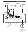
FIXED INSTALLATION
After unpacking the unit, connect the antenna system
to the appropriate antenna input. Connect system
ground to the compression terminal marked GND.
Plug the output cable of the AC Adaptor into the
External DC Input connector on the rear panel of the
SW8 receiver. Plug the AC Adaptor into a source of
120 VAC, 60 Hz power. Refer to Figure 3 for the
diagram of a typical fixed installation.
UNPACKING
Carefully remove the SW8 and included AC Adaptor
wall transformer from the shipping carton and examine
them for evidence of damage. If any damage is noted,
immediately contact the transportation company
responsible for delivery or return the unit to the dealer
from whom it was purchased. Keep the shipping
carton and all packing material for the transportation
company to inspect. The original carton and packing
material should be retained for repackaging should it be
necessary to return the receiver. Inspect the packing
material for any accessories or printed material before
storing the box. Locate the registration card, fill it out,
and immediately return it to the R.L. Drake Company
to insure registration and validation of warranty.
LOCATION
The location of the SW8 is not critical. For added
operating convenience, the carrying handle may be
adjusted to elevate the front of the unit or positioned
behind the front feet. To adjust the handle, disengage
the detents at both sides of the handle at its pivot
points and adjust to desired position until detents are
engaged. To detach (or reinstall) handle from the
receiver, adjust handle to the vertical up position and
bow handle outward at both sides. See Figure 2.
For fixed locations, the SW8 should be operated from
the AC Adaptor. Keep curtains and other flammable
material away from direct contact with the AC Adaptor
to avoid overheating the transformer which could
result in failure or fire.
Vertical Up Position

FM / AIR
ANTENNA 2
ANTENNA 1
EXT DC
INPUT
MASTER
POWER
SHORTWAVE
ANTENNA
SELECT
FM / AIR
ANTENNA
SELECT
LINE
AUDIO
OUT
EXTERNAL
SPEAKER
AIR
SQUELCH
9VDC/
1Amp
+
50
300
GND
500
50
4
EXT WHIP
1 2 WHIP
MADE IN U.S.A.
/ 8
ON OFF
CAUTION:
BALANCED OUTPUT.
DO NOT GROUND.
BATTERY COMPARTMENT
Installation, continued 5
LOW IMPEDANCE
ANTENNA
HIGH IMPEDANCE
ANTENNA
OR
BUILT-IN
TELESCOPING
WHIP ANTENNA
50 OHM COAXIAL CABLE
PL-259
CONNECTOR
PLUG INTO 120VAC,
60Hz AC POWER
TO
TAPE RECORDER
INPUT
FIGURE 3 - INSTALLATION DIAGRAM
- NOTE -
CHECK INTERNAL
BATTERIES PERIODICALLY
IF INSTALLED
EXTERNAL SPEAKER
DO NOT GROUND
NOTE:
Grounding of either speaker
output wire will limit maximum
available audio output and
damage the SW8.
TV/FM
SPLITTER
OR
AC
ADAPTOR
75
0
MS8 Speaker

TONE
VOLUME
POWER
push
H
L
TUNINGBAND
SSB
5
BW
6
SCAN
MEM
LAMP
9
STORE
VFO
SKIP
CLEAR
BEEP
TIMER
CLOCK
AGC
8
AM
SYNC
4
DEL
0
ATT
7
BCB
1
AIR
2
SW
3
F
AGC S AM SYNC
METER
TIMER
+60
+40
+20
9
7
5
3
1
KHz
SW
M E M
6.0
SW8 World Band
Shortwave Receiver
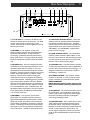
6 Front Panel Description
8 5 1
Pivot Point of
Telescoping
Whip Antenna
7 6 4 3 2
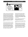
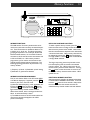
1)Display - The backlit, liquid crystal display provides
the current status of the SW8 such as frequency,
mode, bandwidth, etc. Refer to the 'FRONT PANEL
DISPLAY' section of this manual for a full description.
2)TUNING (VFO) - The dial and the and
buttons are the primary tuning controls of the SW8.
Clockwise rotation of the dial increases frequency and
counterclockwise rotation decreases frequency. The
dial also incorporates variable speed tuning. The faster
the dial is rotated, the faster the tuning speed.
The button increases and the button decreases
the frequency by fixed steps (10 kHz or
9 kHz, selectable on the AM broadcast band, 5 kHz on
the Shortwave band, 100 kHz on the FM broadcast
band and 25 kHz on the Aircraft band) with each
depression. Pressing and holding either button will
allow continuous stepping up or down as long as the
button is depressed.
3)Program Buttons -
F
(Function) - Pressing this button accesses the
secondary functions, printed in orange, on the program
buttons. Press the
F
button first to display
'
F
', then press the desired function button. With
the SW8 not in the SCAN mode, pressing and holding
the
F
button locks all keypad entries, display
settings and tuning knob entries.
BCB
1
BCB - Press to select between the AM or FM
broadcast band. Repeated pressings toggle between
AM and FM. The secondary function of this button is
the digit 1.
AIR
2
AIR - Press to select the Aircraft band. The
secondary function of this button is the digit 2.
SW
3
SW - Press to select the Shortwave band. The
secondary function of this button is the digit 3.
AM
SYNC
4
AM SYNC - Press to select the AM mode of
operation. Successive depressions toggles the synchro-
nous detector on and off. Press
AM
SYNC
4
to turn the
synchronous detector off before selecting SSB modes.
The AM/AM SYNC modes are not accessed in the FM
band. The 'AM SYNC' mode is not accessible in the
Aircraft band. The secondary function of this button is
the digit 4.
SSB
5
SSB - Press to select the SSB mode of operation
('SYNC' must be turned off). Successive depressions
select alternately the LSB or USB modes as dis-
played. The SSB mode of operation is not accessed in
either the FM or Aircraft band modes. The secondary
function of this button is the digit 5.
BW
6
BW - The bandwidth setting can be programmed
to be automatic with mode selection or manual. The
default setting is for automatic selection. Press to
select the desired bandwidth: 6.0 kHz, 4.0 kHz or
2.3 kHz. This function has no action in the FM mode.
The 6.0 kHz bandwidth is automatically selected in the
AM mode. The 2.3 kHz bandwidth is the default for
the SSB modes. All three bandwidths are selectable by
successive depressions of this button for the AM
broadcast, Shortwave and Aircraft bands. To disable
the automatic bandwidth selection with mode, start in
the POWER 'OFF' mode and press and hold the
BW
6
button while pressing the POWER button to put the
SW8 in the POWER ON mode. To enable the
automatic bandwidth selection with mode operation,
repeat the same procedure. The secondary function
for this button is the digit 6.
LSB

ATT
7
ATT - Press to turn on the built-in 20 dB attenua-
tor to reduce the received signal strength in the AM
broadcast and Shortwave bands as required. The
attenuator is not active in the FM and Aircraft bands.
Successive depressions of the button toggles the
attenuator on and off. The secondary function of this
button is the digit 7.
AGC
8
AGC - Press to select either the Slow or Fast
AGC setting for the AM broadcast, Shortwave and
Aircraft bands. The AGC is not selectable in the FM
mode. The secondary function of this button is the digit
8.
LAMP
9
LAMP - Press to turn the display backlighting on
or off. With internal battery operation, the backlighting
automatically turns off after a short delay following a
function change or retuning of the receiver to prolong
battery life. Also, the receiver senses Battery or AC
operation, and allows the lamp to remain lit if on AC.
The secondary function of this button is the digit `9'.
DEL
0
DEL - Press and hold for three seconds to delete
a selected memory channel. Audible beep indicates that
the selected memory channel has been deleted. The
secondary function of this button is the digit 0.
SKIP
SKIP - In the memory mode, press to skip the
current memory channel for a Scan operation. An S
will be displayed to the right of the selected memory
channel number. When an S is displayed next to a
selected memory channel number, press this button to
restore the memory channel for scan operation. The
secondary function of this button is the decimal point
(.) which is used when entering a frequency.
CLEAR
BEEP
CLEAR/BEEP - The beep tone is provided to
indicate that entries have been accepted or to notify of
error. Press this button to enable or disable the 'beep'.
Pressing the
F
button first, clears an incorrectly
entered frequency or other value.
SCAN
MEM
SCAN/MEM - To recall a memory channel at any
time, press the MEM button and within three seconds
of the button depression, enter a two-digit number
between 00 and 69. With MEM displayed, other
adjacent memory channels can be recalled by use of the
/ buttons. The Tuning wheel may be used to tune
from the recalled frequency of the selected memory
channel. Please note that digit entries are interpreted as
frequency entries if the MEM channel number is not
flashing. Pressing the
F
button first, starts scanning
of the current block of 10 channels. The receiver will
stop at each programmed channel for 5 seconds, then
increment to the next memory channel. Channels
programmed for 'SKIP' will not be scanned.
Press this button to stop the scan operation.
Front Panel Description, continued 7
STORE
VFO
STORE/VFO - Press to place receiver in the normal
variable frequency tuning mode (VFO). Select desired
frequency, mode, attenuator, Synchronous detector, AGC,
bandwidth, etc. Pressing the
F
button first, followed
by depression of the
STORE
VFO
button, switches the keypad to
the numeric mode. The MEM symbol will flash in the
display. Enter a two digit number between '00' and '69'
for the desired memory channel. An audible beep will
indicate that the memory channel has been stored with the
newly entered settings.
TIMER
CLOCK
TIMER/CLOCK - Pressing this button once will
display the current time of the current clock. After three
seconds, the display will revert to the current frequency.
Pressing and releasing this button while the time is
displayed will toggle the time display between the two
clocks (local or alternate). The timer will operate accord-
ing to the last displayed clock time. See the 'SETTING
THE 24 HOUR CLOCKS' section of this manual. Pressing
the
F
button first, followed by the TIMER button, will
activate the timer mode. If the Timer has been activated,
the TIMER symbol will be displayed even after the
receiver is turned off. Receiver will automatically turn on
and off as programmed. See the SETTING TIMER ON/
OFF TIMES section of this manual.
4) VOLUME/POWER - Push in on this control to turn the
receiver On or Off. With receiver power on, adjust this
control clockwise to increase the audio level from the
receivers speaker. Be certain to leave the volume setting
at the desired level for TIMER use. The POWER switch
may be disabled by the rear panel 'MASTER POWER'
switch. See the 'Rear Panel Description' section of this
manual.
5) TONE - This control is used to modify the tonal quality
of the audio. Counterclockwise rotation increases the bass
response. Flat response occurs at the 12 OClock setting.
Clockwise rotation increases the treble response.
6) SPEAKER - This is the opening for the internal speaker
of the SW8.
7) HEADPHONE JACK - This connector accepts a 1/8"
stereo/mono headphone connector. Stereo reception is
possible only in the FM mode. All speaker outputs are
automatically switched off when using the headphones.
8) WHIP ANTENNA - The receiver has a built-in tele-
scoping antenna that can be used on all bands. Note that
the pivot point section of the antenna must be exposed
out of its nesting tube to permit vertical extension of the
antenna. Extend the telescoping sections and position the
antenna for best signal reception. Be sure the correspond-
ing rear panel antenna select switch is set to the 'WHIP'
position for WHIP antenna reception.

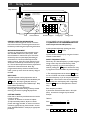
11) SW METER - Indicates the Shortwave
band designators that define a range of frequencies for
each band as follows:
Shortwave Band Designators
120 METER: 2300 - 2500 kHz
90 METER: 3200 - 3400 kHz
75 METER: 3900 - 4000 kHz
60 METER: 4750 - 5060 kHz
49 METER: 5800 - 6200 kHz
41 METER: 7100 - 7600 kHz
31 METER: 9500 - 9900 kHz
25 METER: 11600 - 12100 kHz
22 METER: 13570 - 13870 kHz
19 METER: 15100 - 15800 kHz
16 METER: 17480 - 17900 kHz
13 METER: 21450 - 21850 kHz
11 METER: 25600 - 26100 kHz
12) AIR - Indicates that the Aircraft band (118 - 137
MHz) has been selected.
13) 7-Digit Readout - This display indicates the
operating frequency of the receiver. The frequency is
displayed in 'kHz' for the AM broadcast and Shortwave
bands. The FM and Aircraft band frequencies are
displayed in MHz. In the clock mode, these digits
indicate time in 24 hour format i.e. HH:MM. In the
TIMER mode, indicates time in 24 hour format i.e.
HH:MM. 'L' Indicates that Local Time is being dis-
played in the clock mode. If the 'L' is not illuminated,
alternate time is displayed in the clock display mode.
14) SCAN S - Indicates that the receiver is in the
memory channel SCAN mode and displays the number
of the currently scanned channel, from 00 to 69. In the
MEMORY mode, the 'S' illuminates to indicate that a
particular memory channel will be skipped over when
the SCAN operation is activated.
15) 6.0 4.0 2.3 - Indicates which IF filter is selected.
There is no indication in the FM mode.
16) ST - Indicates that a stereo FM broadcast
station is tuned in when stereo headphones are
plugged into the receivers headphone jack.
1) Bar Graph - This bar graph display indicates the
relative received signal level in S-units and dB above S9.
Each S-unit between S1 and S9 equals an approximately
5 dB change in received signal strength. Each S-unit
above S9 equals an approximately 10 dB change in
received signal strength.
2) TIMER - This annunciator indicates the state of the
Timer as either Active or Inactive. Refer to the
'CLOCK AND TIMER FUNCTIONS' section of this
manual.
3) LOCK - When illuminated, this annunciator
indicates that the Main tuning wheel and keypad are
not active.
4) F Indicates that the
F
button has been pressed
on the keypad to enable the alternate functions
(printed in orange) of the keypad buttons to be active.
5) MEM - This annunciator indicates current
memory location from 00 to 69. MEM will light when
the receiver enters the memory mode. Refer to the
'MEMORY FUNCTIONS' section of this manual.
6) BATT - When operating on internal batteries,
'BATT' blinks to indicate a low charge on batteries.
ATT Indicates that the built-in attenuator is acti-
vated.
7) AGC SF - Indicates the AGC setting, Slow or Fast.
8) AM SYNC - Indicates that the AM mode of recep-
tion is on. If SYNC is also illuminated, then the
synchronous AM mode of detection is on.
9) USB - Indicates that the Upper sideband mode of
detection is on.
LSB Indicates that the Lower sideband mode of
detection is on.
10) FM - Indicates that the FM mode of detection is
on. This mode is selectable only on the FM broadcast
band (87 - 108 MHz).
8 Front Panel Display
16 15 14 13
BATT AGC SF AM SYNC USB FM
METER
TIMER
ON OFF
+60
+40
+20
9
7
5
3
1
KHz
MHz
AIRSW
M E M
SCAN
S
LOCK
F
6.0 4.0 2.3
S T
L
1 2 3 4 5 6 7 8 9 10
11
12

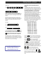
Rear Panel Description 9
1 2 3 4 5 6 7 8 9
FM / AIR
ANTENNA 2
ANTENNA 1
EXT DC
INPUT
MASTER
POWER
SHORTWAVE
ANTENNA
SELECT
FM / AIR
ANTENNA
SELECT
LINE
AUDIO
OUT
EXTERNAL
SPEAKER
AIR
SQUELCH
9VDC/
1Amp
+
50
300
GND
500
50
4
EXT WHIP
1 2 WHIP
MADE IN U.S.A.
/ 8
ON OFF
CAUTION:
BALANCED OUTPUT.
DO NOT GROUND.
BATTERY COMPARTMENT
10
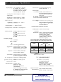
1) EXT DC INPUT - Connect the AC Adaptor wall
transformer output cable to this connector. The SW8
requires 9 VDC power at approximately 1 Amp
current. With external DC power applied, the internal
batteries are not used.
2) ANTENNA
1
- This connector is used when
attaching receiving antennas with coaxial feed lines of
50 ohm nominal impedance. Accepts a standard
PL-259 plug. If selected by the Shortwave Antenna
Select switch (Item 5), this input operates for the AM
Broadcast and Shortwave (100 kHz to 30 MHz) bands
only.
3) FM/AIR Antenna - This input is designed for either
an unbalanced 75 ohm input connection that is encoun-
tered with coaxial feeds, for example, or, for a two
terminal balanced antenna feed with 300 ohm nominal
impedance. Connect to the FM connection of a TV/FM
outdoor antenna feed (splitter), if available. Folded
dipoles or coaxial antennas will also provide good
results with this input for reception of the FM broad-
cast and Aircraft bands. Depending upon the particular
type of antenna feed, connect to one of the FM/AIR
terminals and the GND terminal for an unbalanced 75
ohm input, or, connect to the two 300 ohm terminals
for a balanced 300 ohm input. If selected by the FM/
AIR Antenna Select switch (Item 6), this input operates
for the FM broadcast (87-108 MHz) and the Aircraft
(118-137 MHz) bands only.
4) ANTENNA 2 - This connector can be used to
attach either a low impedance (50 ohm nominal) or
high impedance (500 ohm nominal) antenna. Use the
GND and 50 ohm terminals for a 50 ohm antenna;
use the GND and 500 ohm terminals for a 500 ohm
antenna. If selected by the Shortwave Antenna Select
switch (Item 5), this input operates for the AM Broad-
cast and Shortwave (100 kHz to 30 MHz) bands only.
5) SHORTWAVE ANTENNA SELECT - This switch
selects one of three possible antennas to be used for
the 100 kHz to 30 MHz antenna input. The WHIP
antenna is built-in to the receiver and is located at the
upper left-hand corner of the receivers front panel.
ANTENNA 1 and ANTENNA 2 are described in
Items 2 and 4 on this page.
6) FM/AIR ANTENNA SELECT - This switch allows
selection of either the built-in WHIP antenna, or the
external 75 ohm antenna or 300 ohm antenna connect-
ed at the FM/AIR terminals (Item 3) for the 87-108
MHz and 118-137 MHz frequency ranges.
7) LINE AUDIO OUT - This RCA connector provides
a constant low level audio source that is independent of
the front panel volume and tone control settings. It is
designed to interface to a tape recorder, CW/RTTY
demodulators, amplifiers, etc.
8) EXTERNAL SPEAKER - This connector accepts a
standard 1/4" diameter, 2-circuit, (monaural) phone
plug for connection of an external 4/8 ohm speaker.
DO NOT GROUND!
NOTE: Grounding of either speaker output wire will
limit maximum available audio output and damage the
SW8.
9) AIR SQUELCH - This control is operational only for
the Aircraft band. The control allows muting of the
receiver's audio when no signals are present. Adjust
the control until background noise just disappears
when no signal is being received.
10) MASTER POWER - This is a master power switch
which protects against accidental activation of front
panel power control. If the receiver is operated on
batteries and is not to be used for an extended period
of time, set this switch to the 'OFF' position. For
normal usage of on/off power control from the front
panel, set the 'MASTER POWER' switch to the 'ON'
position.
4
/
75

TONE
VOLUME
POWER
push
H
L
TUNINGBAND
SSB
5
BW
6
SCAN
MEM
LAMP
9
STORE
VFO
SKIP
CLEAR
BEEP
TIMER
CLOCK
AGC
8
AM
SYNC
4
DEL
0
ATT
7
BCB
1
AIR
2
SW
3
F
AGC S AM SYNC
METER
TIMER
+60
+40
+20
9
7
5
3
1
KHz
SW
M E M
6.0
SW8 World Band
Shortwave Receiver
LSB
GENERAL OPERATING INFORMATION
The SW8 has been designed for ease of use. Please
take a few moments to read through this section and
familiarize yourself with general operating information.
MICROPROCESSOR RESET
A power-up reset routine will be activated anytime
after the SW8 COMPLETELY loses power, either
internal batteries or external DC input. This will be
observed by the front panel display illuminating all
annunciators for 3 seconds, followed by the clock
display. However, short term power failures of up to
30 minutes are masked by an internal back-up capaci-
tor. This will allow ample time for battery replacement
without loss of the internal clock. Note: Any
programmmed memory locations will NOT be lost
under a power-up reset due to the memory design of
the SW8.
BEEP TONES
The SW8 responds to all key depressions with an
audible beep unless the beep has been disabled by the
CLEAR
BEEP
button. No beep is generated under any
condition for depressions of the TUNING keys. Beep
tones indicate the following:
One short tone for a key depression.
One long, high tone when storing a memory channel.
One long, low tone for any illegal key depression.
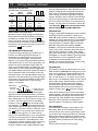
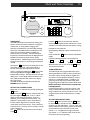
GETTING STARTED
Please refer to the front panel illustrations and set the
controls as shown.
1) Install 6 D batteries or connect AC adaptor.
2) Fully extend whip antenna, adjust to a vertical
position and engage in holder, or connect an external
antenna to appropriate rear panel terminals. Set rear
panel 'ANTENNA SELECT' switch(es) to appropriate
position(s).
3) Press POWER and adjust VOLUME to comfortable
level. (NOTE: Be sure the 'MASTER POWER' switch
on the rear panel is in the 'ON' position.)
4) Select the desired band by pressing one of the
BCB
1
,
AIR
2
, or
SW
3
buttons.
5) Enter the desired frequency by using one of several
methods covered below.
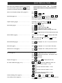
DIRECT FREQUENCY ENTRY
Direct entry of a desired frequency is possible using the
orange numeric keys 0-9 and decimal key. While
entering a frequency, if an incorrect frequency is
entered, pressing the
CLEAR
BEEP
button will clear the entry
in progress and return the SW8 to its previous settings.
** The second depression of the decimal
SKIP
button
acts as an ENTER and causes immediate response to
the entered frequency. If you do not press the decimal
SKIP
button a second time at the end, the SW8 will
automatically enter the frequency after a slight delay.
Press the
F
button to shift keyboard to numeric
entry.
Enter frequency as follows:
A) Shortwave and AM broadcast enter in kHz (kilo-
hertz). A maximum of 6 digits may be entered.
Example:
700 kHz
Press
F
ATT
7
DEL
0
DEL
0
SKIP
SKIP
29660 kHz
Press
F
AIR
2
LAMP
9
BW
6
BW
6
DEL
0
SKIP
SKIP
10 Getting Started
Power/Volume Tuning KnobTuning KeysNumeric KeypadTone
Whip Antenna
**
**

Getting Started, continued 11
SHORTWAVE METER BAND DESIGNATOR
ENTRY
To facilitate tuning to particular sections of the short-
wave band that contain many worldwide broadcasts of
news, information and music, the SW8 permits entry of
the METER band designator. In some cases, the
worldwide broadcast station may not announce its
exact operating frequency, but will announce the
METER band in which it is operating or to which band
it will move to improve worldwide reception at a
particular time of day. By entering this METER band
number, the SW8 automatically tunes to the low
frequency end of the corresponding METER band.
The search for the new station location is thus limited
to a particular smaller section of the entire shortwave
band spectrum. The Shortwave Band Designators and
corresponding frequency range is as follows:
Shortwave Band Designators
120 METER: 2300 - 2500 kHz
90 METER: 3200 - 3400 kHz
75 METER: 3900 - 4000 kHz
60 METER: 4750 - 5060 kHz
49 METER: 5800 - 6200 kHz
41 METER: 7100 - 7600 kHz
31 METER: 9500 - 9900 kHz
25 METER: 11600 - 12100 kHz
22 METER: 13570 - 13870 kHz
19 METER: 15100 - 15800 kHz
16 METER: 17480 - 17900 kHz
13 METER: 21450 - 21850 kHz
11 METER: 25600 - 26100 kHz
Press the
SW
3
button to enter the shortwave band
tuning mode. At this point, you can enter a frequency
with the numeric buttons, or use the Tuning wheel
and or buttons to change frequency.
To enter a shortwave band METER designator, press
the
SW
3
button a second time to display a flashing
METER number entry prompt. Enter one of the
listed two or three digit numbers corresponding to the
desired METER band designator using the numeric
buttons. While the 'METER' annunciator is flashing, the
and buttons can also be used to step
quickly from band to band. After selection of the
Meter band, use the Tuning wheel or and
buttons to change the frequency, or press the
F
button followed by the desired numeric frequency
entry.
BCB
1
AM
SYNC
4
AIR
2
SSB
5
AGC
8
SKIP
BCB
1
F
14258.1 kHz
Press
OR
F
BCB
1
AM
SYNC
4
AIR
2
SSB
5
AGC
8
BCB
1
*
* When the maximum number of allowed digits is
entered, the decimal point will be automatically placed
between the 1 kHz and .1 kHz digits and need not be
entered.
B) Aircraft and FM broadcast enter in MHz (mega-
hertz). A maximum of 5 digits may be entered for FM.
A maximum of 7 digits may be entered for Aircraft.
Example:
97.7 MHz
Press
F
LAMP
9
ATT
7
SKIP
ATT
7
SKIP
121.9 MHz
Press
F
BCB
1
AIR
2
BCB
1
SKIP
LAMP
9
SKIP
** The second depression of the decimal
SKIP
button
acts as an ENTER and causes immediate response to
the entered frequency. If you do not press the decimal
SKIP
button a second time at the end, the SW8 will
automatically enter the frequency after a slight delay.
Attempting to enter a frequency outside the tuning
range of the SW8 will cause the ERROR annunciator to
flash along with the error beep to be heard. The SW8
will then return to its previous settings.
**
**
Downloaded by
Amateur Radio Directory
www.hamdirectory.info

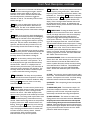
CARRIER
LSB USB
interference from
adjacent station
12 Getting Started, continued
alternate sideband if desired. When AM/SYNC has been
activated, moving the main tuning knob will cause the
SYNC circuit to momentarily disengage (indicated by
SYNC flashing), then back on again when tuning has
stopped. AM SYNC does not function on the AIR band,
and will not operate properly on intermittent transmis-
sions such as those encountered on CB radio bands, for
example. For those types of transmissions, use the AM
mode. Press the
AM
SYNC
4
button to turn the synchronous
detector off before selecting LSB or USB modes.
SSB OPERATION
Tuning in a single sideband (SSB) signal can be somewhat
frustrating for the first time listener. In either of the
SW8s SSB modes, LSB (lower sideband), or USB (upper
sideband), the receiver will select the 2.3 kHz bandwidth
automatically (the SW8 may be programmed to NOT
automatically select a bandwidth. Refer to 'Automatic
Bandwidth Setting With Mode Selection DISABLE
(ENABLE)' in the 'Special Use Features and Functions'
section of this manual). Generally, LSB is used below 10
MHz and USB is used above 10 MHz. When initially
tuning in the desired station, tune slowly. If the station is
unintelligable, try the other sideband, again tuning slowly.
A station tuned in on the wrong sideband is totally
unreadable but a station mistuned on the correct
sideband may sound like Donald Duck. Further tuning
will result in a more normal voice pitch.
FM OPERATION
FM reception is perhaps the easiest mode to use on the
SW8. The AGC and BANDWIDTH settings are not used
in FM. In fact, attempting to activate these buttons will
result in an ERROR beep. All FM stations in the U. S.
end in an odd 100 kHz, i.e., 97.7 MHz, and are spaced
200 kHz apart. The SW8 has the ability to tune in 20 kHz
steps to allow tuning in between stations to help elimi-
nate interference to weaker stations that could be
covered up by stronger adjacent stations. Additionally,
when headphones are used, true stereo reception is
possible. The front panel
S T
annunciator will light
when a stereo station is tuned in with the stereo head-
phones plugged in. The SW8 will automatically switch to
stereo and provide left and right audio from the head-
phone jack only. If the headphones are removed while
listening to a stereo broadcast, the SW8 reverts to
monaural audio from the internal or external speaker.
AGC OPERATION
The SW8 provides the ability to select a Slow or Fast
AGC setting. Either of the two settings will permit
automatic control of the receivers gain thereby produc-
ing a constant audio output free of distortion. Generally,
the Slow AGC setting is preferred for reception of AM
and SSB signals. The Fast AGC setting allows more rapid
automatic receiver gain adjustment to quickly fading
signal levels.
The AGC does not function in the FM mode.
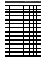
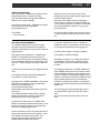
Display
Resolution
100 Hz
100 Hz
100 Hz
10 kHz
100 Hz
Mode
Broadcast
Band:
AM
Shortwave
Band:
AM
USB, LSB
FM
AIR
Tuning
Resolution
100 Hz
100 Hz
50 Hz
20 kHz
100 Hz
10 kHz/9 kHz
5 kHz
5 kHz
100 kHz
25 kHz
Select LSB to
receive this
side only
FREQUENCY RESOLUTION
The SW8 tunes in the following steps:
FRONT PANEL LOCK (UNLOCK)
All keyboard entries, display settings, and entries from
the tuning knob can be locked if desired. First, be sure
the SW8 is not in SCAN. Press and hold the
F
button. The LOCK annunciator will light indicating the
front panel controls are locked out. Power ON/OFF will
still function as well as volume and tone controls. Press
and hold the
F
button to unlock.
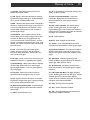
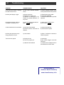
AM SYNCHRONOUS OPERATION
For general tuning and listening, normal AM is best. If,
however, the received signal sounds distorted, or
interference from adjacent stations is present, AM
synchronous should be engaged. The synchronous
detector in your receiver can greatly reduce the severe
audio distortion that can occur due to signal fading. The
detector also permits selectable tuning to either the
upper or lower sideband portion of an AM signal. Since
most all AM (LW, MW and SW) broadcasting generally
uses double-sideband transmission, detection of either of
the two sidebands results in full reception of the trans-
mitted information. The selectable sideband tuning and
detection not only aids reception by permitting tuning to
the stronger or less distorted sideband, but also permits
rejection of the sideband nearer to the interfering
signal(s). For Example:
The synchronous detector will lock to the strongest
signal that is within the IF passband when it is activated.
Most of the time, the strongest signal will be the carrier
of the desired signal. First, be sure the main tuning is set
to within 1 kHz of the desired stations transmitting
frequency. Press the
AM
SYNC
4
button to activate synchro-
nous operation. If adjacent channel interference or any
other undesired signal is sufficiently strong, the synchro-
nous detector may lock to it instead. In that case, press
the
AM
SYNC
4
button to turn the synchronous detector off
and repeat the tuning process. For severe cases of
fading, set the audio bandwidth to 4 kHz. If interference
is present, press the SSB button to select the sideband
with the least interference. If the interference is suffi-
ciently severe to prevent reception, select a narrower IF
bandwidth and retune to the desired signal. After
reception is obtained, select a wider bandwidth and/or

RECALLING A MEMORY LOCATION
To select a specific memory channel, press the
SCAN
MEM
button and then enter a two digit number of the
desired memory channel to be recalled. Make certain
that the successive button depressions are made within
3 seconds of each other. Other memory channels may
be selected by pressing the
SCAN
MEM
button and entering
two digit numbers. If a channel number is selected that
is empty, 'Error' will flash.
The large rotary tuning control may be used to tune
from the frequency that was stored in the selected
memory channel. The `MEM symbol turns off, but
the last memory channel number still shows. Pressing
the
SCAN
MEM
button, causes the receiver to return to the
last selected memory channel number and the `MEM
symbol turns on.
DELETING A MEMORY LOCATION
Select the memory channel to be deleted as described
in RECALLING A MEMORY LOCATION. Press and
hold the
DEL
0
button for three seconds. Beep will be
heard to indicate that the contents stored in the
selected memory channel number have been deleted.
Memory Functions 13
MEMORY FUNCTIONS
The SW8 contains 70 memory locations that can be
used to store and recall commonly monitored frequen-
cies. These 70 locations are divided into blocks of 10,
ie. 00-09, 10-19, 20-29, etc. This allows convenient
grouping of frequencies. As an example, 00-09 could
be AM broadcast stations, 10-19 could be FM broad-
cast stations, 20-29 could be various time stations such
as CHU and WWV, etc. With memory locations
programmed, you can use the scan function to auto-
matically monitor desired memory frequencies. The
following operating parameters may be stored in any
memory location:
1) Frequency 2) Mode 3) Bandwidth 4) AGC setting
5) Attenuator 6) Synchronous detector
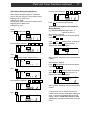
MEMORY LOCATION PROGRAMMING
First, be sure that the SW8 is in the VFO mode (MEM
or SCAN not displayed). If required, press the
STORE
VFO
button to place unit in the VFO mode.
A) Select the desired frequency, mode, bandwidth, etc.
B) Press the
F
button and then the
STORE
VFO
button
(switches keypad to the numeric mode). MEM will
light and the memory channel number will flash.
Within three seconds, enter a two-digit number from
00-69. A confirmation beep is heard.
C) The SW8 will return to the VFO mode and the last
used memory location is displayed in the MEM
portion of the display.
TONE
VOLUME
POWER
push
H
L
TUNINGBAND
SSB
5
BW
6
SCAN
MEM
LAMP
9
STORE
VFO
SKIP
CLEAR
BEEP
TIMER
CLOCK
AGC
8
AM
SYNC
4
DEL
0
ATT
7
BCB
1
AIR
2
SW
3
F
AGC S AM SYNC
METER
TIMER
+60
+40
+20
9
7
5
3
1
KHz
SW
M E M
6.0
SW8 World Band
Shortwave Receiver
LSB

14 Scan Functions
The SW8 provides a time scan function of programmed
memory channels using the
F
button and
SCAN
MEM
button. Scan will begin and end within a 10
channel block of programmed memory channels as
indicated by the most significant digit of the selected
memory channel number.
The receiver will stop at each programmed memory
channel within the block for 5 seconds and then
increment to the next memory channel. Memory
channels that are programmed to be skipped will not
be scanned. The SCAN symbol will be displayed for
the duration of the scan action. Scanning will continue
until the
SCAN
MEM
button is pressed again.
Example for SCAN:
Suppose that memory channels 30 through 39 are
programmed and it is desired to scan these channels.
To initiate the scan action,
Press the
SCAN
MEM
button followed by the two-digit
channel number entry (can enter 30 through 39 for this
example).
Press the
F
button followed by
SCAN
MEM
. The receiver
will begin scanning from the selected memory channel
and continue scanning in sequence: 30 - 31 - 32 -
etc.
Press the
SCAN
MEM
button to stop the scanning action.
Note that if channels 29 and 40 were stored, they
would not be included in a scan of the channels starting
with a 3 as the most significant digit of the channel
number.
Block
Number
0
1
2
3
4
5
6
Memory Channel
Scan Range
00 - 09
10 - 19
20 - 29
30 - 39
40 - 49
50 - 59
60 - 69
MEMORY CHANNEL SKIP
A memory channel can be skipped for scan operations.
While in the MEMORY mode, press the
SKIP
button.
The display will indicate that the SKIP function has
been stored for that particular memory channel
number. An S will be displayed to the right of the
memory channel number on the display. Repeat the
same sequence as described to remove the SKIP
function from a memory channel number.
Example for MEMORY CHANNEL SKIP:
Refer to the previous example on this page. Suppose it
is desired to skip the memory channel number 34
from the scan action:
From the normal variable frequency tuning and
reception mode (VFO) or from the Memory mode,
press the
SCAN
MEM
button followed by the two-digit
number 34.
Press the
SKIP
button. An S will illuminate to the right
of the displayed 34. When the scan action is initiated,
all channel numbers 30 through 39, except 34, will be
scanned. Note that the memory contents of channel
34 still remain, it is skipped over only in the scan
sequence.
To allow channel 34 to again be included in the scan
sequence,
Press the
SCAN
MEM
button followed by the two-digit
number 34.
Press the
SKIP
button to remove the SKIP function
from channel 34 for this example. The S indicator in
the display will turn off.
Page is loading ...
Page is loading ...
Page is loading ...
Page is loading ...
Page is loading ...
Page is loading ...
Page is loading ...
Page is loading ...
Page is loading ...
Page is loading ...
Page is loading ...
Page is loading ...
Page is loading ...
Page is loading ...
-
 1
1
-
 2
2
-
 3
3
-
 4
4
-
 5
5
-
 6
6
-
 7
7
-
 8
8
-
 9
9
-
 10
10
-
 11
11
-
 12
12
-
 13
13
-
 14
14
-
 15
15
-
 16
16
-
 17
17
-
 18
18
-
 19
19
-
 20
20
-
 21
21
-
 22
22
-
 23
23
-
 24
24
-
 25
25
-
 26
26
-
 27
27
-
 28
28
-
 29
29
-
 30
30
-
 31
31
-
 32
32
-
 33
33
-
 34
34


Ask a question and I''ll find the answer in the document
Finding information in a document is now easier with AI
Related papers
Other documents
-
Sangean PAKKET505 Datasheet
-
Sony ICF-SW7600GR Owner's manual
-
-
-
Eton E5 Owner's manual
-
Knoll Antenna Digital Control Switch Quick Setup Manual
-
Grundig 800 MILLENNIUM User manual
-
Sony Radio ICF-SW7600 User manual
-
-