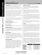
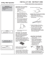
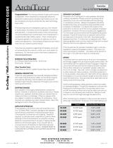
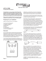
AudioSource 6.5" CEILING LCR CINEMA SPEAKER is specifically engineered for mounting in the ceiling as front channel Left, Center, and Right home theater speakers. It can also be used as a single center channel speaker or in conventional stereo pairs. The ACLCR6C can also be installed for rear channel sound where conventional in-wall or floor speakers cannot be used. Additionally, the tweeter in the ACLCR6C speakers can be swiveled to direct the sound to the desired listening area, ensuring an immersive and tailored audio experience.
AudioSource 6.5" CEILING LCR CINEMA SPEAKER is specifically engineered for mounting in the ceiling as front channel Left, Center, and Right home theater speakers. It can also be used as a single center channel speaker or in conventional stereo pairs. The ACLCR6C can also be installed for rear channel sound where conventional in-wall or floor speakers cannot be used. Additionally, the tweeter in the ACLCR6C speakers can be swiveled to direct the sound to the desired listening area, ensuring an immersive and tailored audio experience.


-
 1
1
-
 2
2
-
 3
3
-
 4
4
AudioSource ACLCR6C User manual
- Type
- User manual
- This manual is also suitable for
AudioSource 6.5" CEILING LCR CINEMA SPEAKER is specifically engineered for mounting in the ceiling as front channel Left, Center, and Right home theater speakers. It can also be used as a single center channel speaker or in conventional stereo pairs. The ACLCR6C can also be installed for rear channel sound where conventional in-wall or floor speakers cannot be used. Additionally, the tweeter in the ACLCR6C speakers can be swiveled to direct the sound to the desired listening area, ensuring an immersive and tailored audio experience.
Ask a question and I''ll find the answer in the document
Finding information in a document is now easier with AI
Related papers
-
AudioSource AE6C User manual
-
AudioSource AC8C Installation guide
-
AudioSource AC8C User manual
-
AudioSource 2-Way User manual
-
AudioSource AS8C Installation guide
-
AudioSource AC8CD User manual
-
AudioSource AC6W User manual
-
AudioSource AE8S User manual
-
AudioSource AC6W User manual
-
AudioSource AE515 Installation guide
Other documents
-
 ArchiTech SC-602E-4BULK Installation guide
-
 Silver Ticket Products 5252W User manual
-
 ArchiTech SC-620f Installation guide
-
 Phoenix Gold ATCLCR6 User manual
-
Phoenix Gold Speaker ATc8 User manual
-
Pure Acoustics NR 25 User manual
-
Pure Acoustics NR 6 User manual
-
Phoenix Gold ATC6DM User manual
-
Jamo 6.5K4 2-WAY 6 User manual
-
Micca M-CS User manual


