Page is loading ...


Operation manual VERA S15
2
Introduction
Thank you for choosing a high-quality product “MADE IN GERMANY” from TW AUDiO.
The VERA S15 is the most compact bass extension of the VERA10 loudspeakers. Weighing
only 23.5 kg [51.81 lbs] and being just 44 cm [17 in] tall, it’s the first choice for applications
with load restricted flying points and low rigging heights.
With the optional PWS15 passive crossover, the VERA S15 can do even more – giving active
or passive bass support to our M and C series loudspeakers.
If you lend your product to another party, inform that party of the safety-related operating pro-
cedures and hand over this assembly guide. If you require additional copies of this manual,
you can obtain them free of charge from TW AUDiO or download them from www.twaudio.de
Instructions in this user manual
Strictly adhere to the instructions contained in this operating manual that are marked as
follows:
This symbol in combination with the signal word “Caution” identifies a potentially hazardous
situation. Failure to comply with this safety instruction can lead to light or moderate injury.
This symbol in combination with the signal word “Note” identifies a potentially hazardous
situation. Failure to comply with this safety instruction can lead to product damage.
This symbol in combination with the signal word “Tip” identifies additional information or
notes that will simplify working with TW AUDiO products on the basis of practical experience.
This symbol in combination with the signal word “Warning” identifies a potentially hazardous
situation. Failure to comply with this safety instruction can lead to serious injury or even death.
NOTE
TIP
CAUTION
WARNING
This symbol in combination with the signal word “Warning” identifies a potentially hazardous
situation for persons with a pacemaker. Failure to comply with this safety instruction can lead
to serious injury or even death.
WARNING

Operation manual VERA S15
3
Notes on the product
Read manual
before use!
Before using the device, carefully read the operating manual and keep it with the
VERA S15 loudspeaker.
General information
Operation manual: OM-VERA S15
Version 1.1 en, 11/2018
© by TW AUDiO 2018; all rights reserved.
All information contained in this operating manual was correct to the best of our knowledge
at the time of printing.
Quality warranties or assurance of suitability for a certain type of use based on the technical
specifications, dimensions and weights are not granted by TW AUDiO.
TW AUDiO also shall not assume liability for any secondary damage (property damage and/or
personal injury) nor for the failure to comply with this operating manual!
TW AUDiO reserves the right to update this document based on recent developments.
TW AUDiO GmbH
Osterholzallee 140
71636 Ludwigsburg
Germany
Phone : + 49 (0) 71 41-48 89 89 0
Fax: + 49 (0) 71 41-48 89 89 99
E-Mail: [email protected]
WWW: www.twaudio.de

Operation manual VERA S15
4
Content
1. Safety | Intended use ...................................................................................................... 5
2. Overview ........................................................................................................................ 7
2.1 Components ........................................................................................................... 7
2.2 Variants ................................................................................................................... 8
2.2.1. VERA S15A/ VERA S15P models ....................................................................... 8
2.3 Operation modes ..................................................................................................... 9
2.3.1 MODE 1 - ACTIVE (BI-AMPED) .......................................................................... 9
2.3.2 MODE 2 - PASSIVE 1 (M-SYS-ONE) ................................................................ 10
2.3.3 MODE 3 - PASSIVE 2 (M-SYS-TWO) ............................................................... 11
3. Technical data .............................................................................................................. 12
3.1 Data sheet ............................................................................................................. 12
3.2 Connection diagram .............................................................................................. 13
3.2.1 Variant: VERA S15A .......................................................................................... 13
3.2.2 Variant: VERA S15P .......................................................................................... 13
4. Commissioning ............................................................................................................. 14
4.1 Setup .................................................................................................................... 14
4.2 M20 pole mount flange .......................................................................................... 14
4.3 Operation .............................................................................................................. 17
4.4 Connecting the cable ............................................................................................. 18
5. Transport and storage .................................................................................................. 19
6. CE Conformity Declaration ............................................................................................ 20
7. Disposal ....................................................................................................................... 21

Operation manual VERA S15
5
1. Safety | Intended use
Please adhere to the following safety instructions to avoid risks when operating loudspeakers.
The VERA S15 loudspeaker was developed for use in professional sound systems. The
loudspeaker may only be used by trained and qualified personnel.
Note the operating modes described in this operating manual. Other uses are not permis-
sible.
Damage caused by improper use is not covered by TW AUDiO.
Loudspeakers generate an electromagnetic field. Persons with pacemakers are not permit-
ted to remain in the immediate vicinity of loudspeakers as the electromagnetic fields can
cause pacemakers to malfunction.
When working with heavy loads exceeding 20 kg (44,09 lbs.), use suitable aids (dollies, hois-
ting slings, etc.). Multiple persons may be required depending on the situation.
Ensure that the units are in a stable position and are firmly attached. A falling loudspeaker can
result in serious personal injury and property damage.
When using and assembling TW AUDiO loudspeakers, only use materials specified by
TW AUDiO. These tasks must be performed by qualified personnel. Adhere to the applicable
safety regulations.
WARNING
When setting up loudspeakers, ensure that they are not exposed to the following ambient
conditions:
• direct sunlight
• Humidity
• Jolting
• Dust
Keep away from the immediate vicinity of loudspeakers that are operated at high sound pres-
sure levels. These loudspeaker systems are capable of endangering your health. Sound levels
beginning as low as approximately 90 dB SPL can lead to long-term hearing impairment.
WARNING
Avoid:
• Feedback
• Distorted signals (clipping) and
• Peaks resulting from switching on devices, plugging in devices or unplugging devices during
operation.
Such signals can lead to loudspeaker overload and ultimately to loudspeaker failure.
WARNING
NOTE
NOTE

Operation manual VERA S15
6
Ensure that the loudspeaker is not exposed to permanent thermal overloads. Thermal over-
loads may cause a fire and result in serious personal injury and property damage.
WARNING
Note that TW AUDiO does not provide a warranty for damage that can be attributed to this
type of overload and therefore cannot be held liable for any secondary damage.
A permanent magnetic field is present in the immediate vicinity of loudspeakers. Ensure that
objects which react sensitively to magnetic fields are not located in the immediate vicinity of
the loudspeaker. In particular, this applies to magnetic storage media, magnetic stripe cards
such as debit cards and CRT displays. A distance of approximately one meter is sufficient to
avoid damage.
Check loudspeakers and accessory parts regularly for visible wear. This is essential to ensure
continuing fault-free operation. Worn parts should be replaced immediately. Spare parts are
available from TW AUDiO.
NOTE
NOTE

Operation manual VERA S15
7
2. Overview
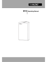
2.1 Components
1. 15“ cone driver
2. Front eyelet
3. M20 pole mount flange for attaching a distance rod
4. 15 mm multiplex enclosure – polyurea-coated
5. Milled recess for rubber feet for safely stacking loudspeakers
6. VERA S15 rigging plate, „rear“
7. Locking pin 8x30
8. Splay link
9. VERA S15 rigging track, „front“
10. Locking pin 8x20
11. Standard connection panel
12. Type label
13. Passive crossover PWB15
14. Rubber feet (4 units)
15. Ergonomic carrying handles (right and left)
Figure 2.1 - Overview
1
23 5
4
6
7
8
9
10
15
14
1312
11
VERA S15A VERA S15P

Operation manual VERA S15
8
2.2 Variants
The VERA S15 loudspeaker comes in two different variants. These variants are the VERA S15A
(ACTIVE model) and VERA S15P (PASSIVE model).
The standard model of the VERA S15 loudspeaker is the VERA S15A variant, which can only
be operated in the „ACTIVE“ operating mode. It is supplied with a standard connection panel.
The separation occurs in the DSP of the amplifier.
The VERA S15P model can also be operated in the „PASSIVE 1“ and „PASSIVE 2“ modes. This
permits the connection of an additional loudspeaker on the high-pass output or the link out-
put when operating with only one amplifier channel. The installed passive cross-over (pos.13
“Figure 2.1 - Overview” on page 7) has two selector switches, which are described in the
following section.
2.2.1. VERA S15A/ VERA S15P models

Operation manual VERA S15
9
Figure 2.3.1 - Connection diagram VERA S15P
2.3 Operation modes
In operation mode 1 „ACTIVE“, the internal passive crossover is switched out of the signal
path, and the separation of the loudspeakers must take place in the DSP of the amplifier. The
pin connection of the VERA S15 loudspeaker is switched to pin 2+/-.
1. Set the upper switch to “OFF”! This must never be set to “ON” when no loudspeaker is
connected to the high pass output!
2. Switch the bottom switch to ACTIVE mode.
3. Connect the amplifier to the “input” connector. Do not inadvertently connect it to the high
pass output!
WARNING
two amplifier channels / 4-wire speaker cable required
Pin 1+/- TOP speaker
Pin 2+/- VERA S15 subwoofer
The top selector switch is used to activate the high pass output. The bottom selector switch
is used to activate the passive crossover and changes the pin assignment of the connection
sockets.
2.3.1 MODE 1 - ACTIVE (BI-AMPED)
OUTPUT to
additional
speaker
INPUT

Operation manual VERA S15
10
Figure 2.3.2 - Connection diagram B15P
In operation mode 2 „PASSIVE 1“, the VERA S15 loudspeaker and other loudspeakers are
operated on the „link output“ output on pin 1+/-.
1. Set the upper switch to “OFF”! This must never be set to “ON” when no loudspeaker is
connected to the high pass output!
2. Switch the bottom switch to „PASSIVE mode“.
3. Connect the amplifier to the “input” connector. Do not inadvertently connect it to the
high pass output!
WARNING
one amplifier channel is required
Pin 1+/- VERA S15+M15
Pin 2+/- free
Note that the total impedance may vary depending on the connected loudspeaker. See
“Connecting the cable” on page 18.
NOTE
Never change the operation mode while the loudspeaker is in operation. This may damage the
connected loudspeakers.
Operation mode 1 „ACTIVE“ additionally requires the correct preset at the amplifier.
NOTE
2.3.2 MODE 2 - PASSIVE 1 (M-SYS-ONE)
OUTPUT to
speaker
INPUT
!
Be sure HP-output switcher is in
OFF
position.
Keeping
ON
position without any load may couse a damage.
IMPORTANT!

Operation manual VERA S15
11
Figure 2.3.4 - Connection diagram B15P
In operation mode 3 „PASSIVE 2“, the VERAS15 loudspeaker is operated with an M8 loudspe-
aker on the „high pass output“. The separation of the two loudspeakers is performed via the
internal passive crossover. The pin connection of the VERA S15 loudspeaker is switched to
pin 1+/-.
1. Connect the M8 loudspeaker to the high pass output! Never connect an amplifier to this
connector!
2. Switch the top switch to „ON“.
3. Switch the bottom switch to „PASSIVE mode“.
4. Connect the amplifier at the „Input“-pin.
WARNING
2.3.3 MODE 3 - PASSIVE 2 (M-SYS-TWO)
Never change the operation mode while the loudspeaker is in operation. This may damage the
connected loudspeakers.
NOTE
one amplifier channel is required
Pin 1+/- VERA S15+M8
Pin 2+/- free
OUTPUT to M8
INPUT

Operation manual VERA S15
12
3.1 Data sheet
Variant
VERA S15A VERA S15P
Drivers 1x 15“ LF
Frequency
response 40 - 1500 Hz
Power handling
(program/Peak) 1200 / 2400 W ACTIVE
1200 / 2400 W
PASSIVE 1
1200 / 2400 W
PASSIVE 2
1200 / 2400 W
Impedance 4 Ω 4 Ω 4 Ω 4 Ω
Max. SPL / 1 m 127 dB
Dimensions
(h x w x d) 506 x 440 x 560 mm [19,92 x 17,32 x 22,05 in]
Weight 23 kg [50,7 lbs] 25,3 kg [55,77 lbs]
Surface Polyurea-coated
3. Technical data

Operation manual VERA S15
13
3.2 Connection diagram
Figure 3.2.1 - Connection diagram VERA S15A
3.2.1 Variant: VERA S15A
Figure 3.2.2 - Connection diagram VERA S15P
3.2.2 Variant: VERA S15P
input
and
link output
Never connect this output to
an amplifier. Risk of damage!
High pass output
to drive 8 ohm load
ON HP-output
PASSIVE mode
input is pin 1 +/-
HP-output OFF
ACTIVE mode
input is pin 2 +/-
4 OHM
2,5 OHM
(with M8)
+
--
PIN 1+
PIN 1–
PIN 1+
PIN 1–
PIN 2+
PIN 2–
PIN 1+
PIN 1–
PIN 2+
PIN 2–
15"
parallel
HP
LP 1st order
LP 2nd order
ACTIVE / PASSIVE
HP-output ON / OFF
4 OHM
+
--
rear connectors
parallel
PIN 1+
PIN 1–
PIN 2+
PIN 2–
PIN 1+
PIN 1–
PIN 2+
PIN 2–
15"

Operation manual VERA S15
14
4.1 Setup
The VERA S15 loudspeaker is designed for hanging and standing operation.
TW AUDiO empfiehlt für die Sicherung und Montage der Lautsprecher ausschließlich das von
TW AUDiO spezifizierte Zubehör.
NOTE
Ensure that the loudspeakers are securely attached to prevent personal injury and prop-
erty damage. Secure stacked loudspeakers properly so that they can be tipped by 10° in
any direction without toppling.
WARNING
4.2 M20 pole mount flange
For all system components mounted on top of the M20 pole mount flange, observe the res-
pective operating instructions!
Also be sure to observe all of the following warnings:
Make sure that all system structures are located on a firm, level surface and that the surface
can bear the total weight!
WARNING
Make sure that the maximum load of 50 kg / 110 lbs for the M20 pole mount flange is not
exceeded! See figure 2.1 – Item 10.
WARNING
Make sure that no unauthorized persons can access the system structures!
Cordon off the area professionally!
WARNING
Please note that the M20 pole mount flange is not designed for side loads! See figure 2.1 –
Item 10.
Make sure that no external forces are applied to the system structures. No objects or persons
should lean against the structures, no objects such as balls should be thrown against them.
WARNING
4. Commissioning

Operation manual VERA S15
15
Before setting up the system outdoors, consider unexpected wind conditions at the opera-
tion site!
Disassemble your system immediately when wind speeds exceed 8 bft (34 to 40 kn / 62 to
74 kph / 38.5 to 46 mph) and secure the system components!
Make sure that there are no persons in the immediate vicinity of the system structure!
WARNING
Figure 4.2.1 - system setup VERA S15
Please note that only centered loads should be placed on the M20 cabinet flange – see
figure 2.1 – Item 10.
WARNING
Make sure that the system structures are not operated over the audience at wind speeds in
excess of 6 bft (22 to 27 kn / 39 to 49 kph / 24.2 to 30.45 mph) and that there are no persons
in the immediate vicinity of the system structure!
WARNING


Operation manual VERA S15
17
4.3 Operation
Operation of the VERA S15A speaker requires a DSP-Controller. TW AUDiO recommends
operating the VERA S15P loudspeaker on a DSP-Controller. For this purpose, only presets
developed by TW AUDiO are recommended. The TW AUDiO system racks are ideally suited
for this purpose.
Make sure that the amplifier’s specifications meet the requirements. Using an amplifier that
doesn’t meet the specifications can destroy the loudspeaker.
Please note the technical data in section 3.1 on page 12.
NOTE
Before connecting the loudspeaker to the amplifier, ensure that the right preset has been
loaded.
Using the wrong preset or a preset not provided by TW AUDiO preset can destroy the speaker.
NOTE

Operation manual VERA S15
18
4.4 Connecting the cable
To create a cable connection with an amplifier rack from TW AUDiO, proceed as follows.
Ensure that the cable cross sectional area is sufficient (at least 1.5 mm²) to avoid power losses.
TW AUDiO recommends using the loudspeaker cables available from TW AUDiO.
When connecting the cables to the loudspeaker, ensure that polarity (+/-) and pin assignment
(1/2) are correct. Incorrect connection can lead to a significant change in the loudspeaker’s
sound characteristics and may damage the driver.
The pin connections of the VERA S15 loudspeaker can be found in section 3.2 (“Connection dia-
gram”) on page 13.
The internal wiring of the VERA S15 loudspeaker allows for parallel connection of multiple
loudspeaker units.
Please note that parallel connections will decrease the total impedance of your loudspeaker
configuration.
The total impedance and the resulting power of the speaker configuration must match the
output power of the amplifier.
NOTE

Operation manual VERA S15
19
To transport up to six VERA S15 loudspeakers with a single person, TW AUDiO recommends
using the VERA DL15 transport cart.
When transporting and storing the unit, it is important to ensure that the surface and front
grill of the loudspeaker are not damaged. Moisture can penetrate through exposed wood
surfaces and cause the wood to swell. A bent or broken front grill will no longer adequately
protect the sensitive speaker membranes.
In addition, appreciable dust deposits may considerably impair the functionality of a loudspe-
aker membrane. For this reason, the loudspeakers should be transported and stored in a
safe, careful, dry and largely dust-free manner.
The following accessory parts for transport and storage are available from TW AUDiO:
• VERA DL15 (transport cart)
The original packaging is unsuitable as permanent storage and transport packaging.
NOTE
5. Transport and storage
Due to the VERA S15 loudspeaker weighing over 20 kg [44.09 lbs.], two persons are required
to handle and transport the unit.

Operation manual VERA S15
20
Copy and translation of the original CE Conformity Declaration:
We hereby declare that the below-referenced components by virtue of their design and
construction, and in the configuration placed on the market by us, satisfy the safety and
health requirements of the applicable EC directives. This declaration becomes invalid in
case of modifications that have not been approved by us.
This declaration applies to the following components
• VERA S15A
• VERA S15P
as well as all model variants based on these, provided that they correspond to the original
factory models and have not been technically modified in any way.
Applicable directives:
• 2001/95/EG
• 2011/65/EU
Applicable national standards and technical specifications:
• DIN EN 18 800
• DIN EN ISO 12 100
• BGV C1 / BGI 810-3
• EN 50581: 2013-02
Ludwigburg, Germany, January 1st, 2008
Tobias Wüstner
6. CE Conformity Declaration
/