Page is loading ...

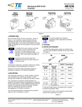
Connector Specific Kit 768341-1
Typical Applicators
Lower Insert Upper Tool
AMP-LATCH Hand Tool Kit
768340-1 (Ref)
Manual Arbor Frame
Assembly 91085-2 (Ref)
Base Assembly for the
Universal Arbor Tool
768338-1 (Ref)
© 2011 Tyco Electronics Corporation, a TE Connectivity Ltd. Company
All Rights Reserved
*Trademark
TE Connectivity, TE connectivity (logo), and TE (logo) are trademarks. Other logos, product and/or Company names may be trademarks of their respective owners.
1 of 3
Instruction Sheet
TOOLING ASSISTANCE CENTER
1-800-722-1111
PRODUCT INFORMATION
1-800-522-6752
This controlled document is subject to change.
For latest revision and Regional Customer Service,
visit our website at www.te.com LOC B
408-9831
Connector Specific Kit 768341-1 18 MAY 11 Rev B
PROPER USE GUIDELINES
Cumulative Trauma Disorders can result from the prolonged use of manually powered hand tools. Hand tools are intended for occasional use
and low volume applications. A wide selection of powered application equipment for extended-use, production operations is available.
Figure 1
1. INTRODUCTION
This instruction sheet covers the description, cable
requirements, and installation procedures for
Connector-Specific Kit 768341-1, which is used with
AMP-LATCH Hand Tool Kit 768340-1 (see instruction
sheet 408-9828) and Base Assembly Universal Arbor
Tool 768338-1 (see 408-9827). The connector-
specific kit will terminate AMP-LATCH Standard and
Novo Receptacle Connectors having 1.27 mm [.050
in.] centerline spacing to ribbon cable (see Figure 2).
The Base Assembly Universal Arbor Tool is used with
Manual Arbor Frame Assembly 91085-2 and
Pneumatic Auto-Cycle Unit 91112-3. Refer to
408-7777 and 408-6732, respectively, for tooling
information.
NOTE
i
Dimensions on this sheet are in metric units [ with
U.S. customary units in brackets.]

408-9831
2 of 3
Rev B
2. DESCRIPTION (Figure 1)
The connector-specific kit features an upper tool and a
lower insert. The upper tool applies an even force over
the length of the connector during termination. The
lower insert positions the connector on the tooling
assembly. Each component is marked "RCPT."
3. CABLE REQUIREMENTS
The connector-specific kit will terminate ribbon cable
with 26 AWG solid or stranded conductors, 28 AWG
solid or stranded conductors, or 30 AWG solid
conductors to all AMP-LATCH Standard and Novo
Receptacle Connectors. Refer to Figure 2 for the
recommended cable dimensions.
NOTE: Accumulative tolerance for cable conductors 1 through
34 is +.254 [.010] and through 60 is + .38 [.015].
CONDUCTOR DIMENSION
SIZE
(AWG) TYPE “A” “B”
26 Stranded or Solid 0.889 mm
[[.035 In.]
1.27 mm [.050 In.]
X (Total No. of
Conductors Minus
One)
28 Stranded or Solid
30 Solid
Figure 2
CAUTION
!
The cable must be cut 90° to the edge of the cable;
other wise an improper termination will result. We
suggest you use a guillotine-type cable cutter, such
as the Carpenter Model 95 which can be
purchased from:
Carpenter Manufacturing Co., Inc.
Fairgrounds Drive
Manlius, NY 13207
Lower Insert
Upper Tool
Locators
AMP-LATCH Hand Tool Kit 768340-1 (Ref)
(Includes AMP-LATCH Hand Tool Subassembly
768942-1 and Base Assembly Universal Hand
Tool 768339-1. Refer to 408-9846 and 408-9826.)
Slot of Fluted Plater
Figure 3
4. CONNECTOR-SPECIFIC KIT INSTALLATION
(FIgure 3 and Figure 4)
NOTE
i
For hand tool applications, mount the hand tool
onto a suitable work surface, whenever possible,
before terminating the connectors. Refer to the
bench-clamping instructions in 408-9828,
packaged with the AMP-Latch Hand Tool Kit.
1. Slide the upper tool onto the upper tool mount.
2. Slide the lower insert into the slot of the fluted
plate.
This completes the installation procedure.
NOTE
i
For information concerning termination procedures,
refer to 408-9828 packaged with the AMP-LATCH
Hand Tool Kit and 408-9827 packaged with the
Base Assembly Universal Arbor Tool.

Lower
Insert
Upper
Tool
Base Assembly
Universal Arbor Tool
768338-1 (Ref)
Slot of Fluted Plate
408-9831
3 of 3
Rev B
Figure 4
5. CONNECTOR-SPECIFIC KIT INSPECTION
Connector-Specific Kit 768341-1 has been inspected
and should be verified with the information provided in
Figure 5. It is recommended that the connector-
specific kit be inspected immediately upon its arrival at
your facility (and at regularly scheduled intervals) to
ensure that the kit components have not been
damaged during handling.
For additional information concerning connector-
specific kits, or to purchase additional kits, contact
your local TE representative or:
CUSTOMER SERVICE (038-035)
TYCO ELECTRONICS CORPORATION
PO BOX 3608
HARRISBURG PA 17105-3608
6. REVISION SUMMARY
Since the previous release of this instruction sheet,
the new company logo has been applied.
Upper Tool
100.08 [3.94]
89.92 [3.54]
20.83 [.82]
6.22 [.245]
21.84 [.86] 5.59 [.22]
12.19 [.48]
Lower Insert
Figure 5
/


