Page is loading ...

ALL phases of this installation must comply with NATIONAL, STATE AND LOCAL CODES
IMPORTANT — This Document is customer property and is to remain with this unit. Please return to service
information pack upon completion of work.
Installer’s Guide
These instructions do not cover all variations in
systems nor provide for every possible contingency
to be met in connection with installation. All phases
of this installation must comply with NATIONAL,
STATE AND LOCAL CODES. Should further information
be desired or should particular problems arise which are
not covered sufficiently for the purchaser’s purposes, the
matter should be referred to your installing dealer or local
distributor.
A. GENERAL
WARNING
!
This information is intended for use by individuals pos ses-
s ing adequate backgrounds of electrical and mechanical
experience. Any attempt to repair a central air condition ing
product may result in personal injury and or property damage.
The manufacturer or seller cannot be respon sible for the
interpretation of this information, nor can it assume any liability
in connection with its use.
NOTICE:
Trane has always recommended installing Trane
approved matched indoor and outdoor systems.
The benets of installing approved matched systems
are maximum efciency, optimum performance and
best overall system reliability.
WARNING
!
These units use R-410A refrigerant which operates at 50 to 70%
higher pressures than R-22. Use only R-410A approved service
equipment. Refrigerant cylinders are painted a “Rose” color to
indicate the type of refrigerant and may contain a “dip” tube
to allow for charging of liquid refrigerant into the system. All
R-410A systems use a POE oil that readily absorbs moisture from
the atmosphere. To limit this “hygroscopic” action, the system
should remain sealed whenever possible. If a system has been
open to the atmosphere for more than 4 hours, the compressor
oil must be replaced. Never break a vacuum with air and always
change the driers when opening the system for component
SSC-APG011-EN.
Check for transportation damage after unit is uncrated.
Report promptly, to the carrier, any damage found to the
unit.
To determine the electrical power requirements of the unit,
refer to the nameplate of the unit. The electrical power
available must agree with that listed on the nameplate.
Condensing Units
4TTR3
18-AC71D1-5
OF THE UNIT
1. When removing unit from the pallet, notice the tabs on
the basepan. Remove tabs by cutting with a sharp tool
as shown in Figure 2 (see page 2).
2. The unit should be set on a level support pad at least
as large as the unit base pan, such as a concrete
slab. If this is not the application used please refer to
application bulletin SSC-APG002-EN.
3. The support pad must NOT be in direct contact with
any structure. Unit must be positioned a minimum
of 12" from any wall or surrounding shrubbery to
insure adequate airflow. Clearance must be provided
1
CAUTION
!
UNIT CONTAINS R-410A REFRIGERANT!
R-410A OPERATING PRESSURE EXCEEDS THE
LIMIT OF R-22. PROPER SERVICE EQUIPMENT IS
REQUIRED. FAILURE TO USE PROPER SERVICE
TOOLS MAY RESULT IN EQUIPMENT DAMAGE OR
PERSONAL INJURY.
SERVICE
USE ONLY R-410A REFRIGERANT AND
APPROVED POE COMPRESSOR OIL.

© 2009 Trane 18-AC71D1-5
Installer’s Guide
in front of control box (access panels) & any other side
requiring service access to meet National Electrical
Code. Also, the unit location must be far enough away
from any structure to prevent excess roof run-off water
from pouring directly on the unit. Do not locate unit(s)
close to bedroom(s).
4. The top discharge area must be unrestricted for at least
five (5) feet above the unit.
5. When the outdoor unit is mounted on a roof, be sure the
roof will support the unit’s weight. Properly selected
isolation is recommended to prevent sound or vibration
transmission to the building structure.
6. The maximum length of refrigerant lines from outdoor
to indoor unit should NOT exceed sixty (60) feet.
7. If outdoor unit is mounted above the air handler,
maximum lift should not exceed sixty (60) feet (suction
line). If air handler is mounted above condensing unit,
maximum lift should not exceed sixty (60) feet (liquid
line).
NOTE:
Refer to “Refrigerant Piping Software” Pub. No. 32-3312-0*
(the position of the * denotes the latest revision number).
8. Locate and install indoor coil or air handler in
accordance with instruction included with that unit.
C. INSTALLING REFRIGERANT LINES
CAUTION
!
If using existing refrigerant lines make certain that all
joints are brazed, not soldered.
Condensing units have provisions for braze connections.
Pressure taps are provided on the service valves of outdoor
unit for compressor suction and liquid pressures.
The indoor end of the recommended refrigerant line sets
may be straight or with a 90 degree bend, depending upon
situation requirements. This should be thoroughly checked
out before ordering refrigerant line sets.
The gas line must always be insulated.
CAUTION
!
In scroll compressor applications, dome temperatures
may be hot. Do not touch top of compressor, may cause
minor to severe burning.
The units are factory charged with the system charge
required when using fifteen (15) feet of rated connecting
line. Unit nameplate charge is with twenty-five (25) feet of
line set.
Final refrigerant charge adjustment is necessary.
Use the Subcooling Charging procedure on page 6 or in the
outdoor unit Service Facts.
1. Determine the most practical way to run the lines.
2. Consider types of bends to be made and space limitations.
NOTE:
Large diameter tubing will be very difcult to rebend once
it has been shaped.
3. Determine the best starting point for routing the
refrigerant tubing — INSIDE OR OUTSIDE THE
STRUCTURE.
4. Provide a pull-thru hole of sufficient size to allow both
liquid and gas lines.
5. Be sure the tubing is of sufficient length.
6. Uncoil the tubing — do not kink or dent.
7. Route the tubing making all required bends and
properly secure the tubing before making connections.
8. To prevent a noise within the building structure due to
vibration transmission from the refrigerant lines, the
following precautions should be taken:
a. When the refrigerant lines have to be fastened
to floor joists or other framing in a structure, use
isolation type hangers.
b. Isolation hangers should also be used when
refrigerant lines are run in stud spaces or enclosed
ceilings.
c. Where the refrigerant lines run through a wall or
sill, they should be insulated and isolated.
d. Isolate the lines from all ductwork.
The Brass Liquid and Gas Line Service Valves are factory
shipped in the seated position to hold factory charge. The
pressure tap service port (when depressed) opens only to
the field brazing side of the valve when the valve is in the
seated position. The liquid line valve is not a back seating
valve (see WARNING below).
WARNING
!
Extreme caution should be exercised when opening
counterclockwise only until the stem contacts the rolled
edge. (See Figure 3.) No torque is required.
The Brass Gas Line Ball Service Valve is shipped in the
closed position to hold the factory refrigerant charge. The
pressure tap service port (when depressed) opens only
to the field brazing side when the valve is in the closed
position. The Gas Line Ball Service Valve is full open with
a 1/4 turn. See Figure 4.
1. Remove lower access cover to access service valves.
2. Before brazing, remove plugs from external copper stub
tubes. Clean internal and external surfaces of stub
tubes prior to brazing.
3. Cut and fit tubing, minimizing the use of sharp
90° bends.
4. Insulate the entire gas line and its fittings.
5. Do NOT allow uninsulated liquid line to come in direct
contact with bare gas line.
6. Precautions should be taken to avoid heat
damage to the pressure tap valve core during
brazing. It is recommended that the pressure
tap port valve core be removed and a wet rag
wrapped around the valve body.
2

18-AC71D1-5 3
Installer’s Guide
NOTE:
Use care to make sure that no moisture enters pressure
tap port, while wet rag is being used.
NOTE:
Precautions should be taken to avoid heat damage to
basepan during brazing. It is recommended to keep the
ame directly off of the basepan.
7. Use a Dry Nitrogen Purge and Brazing Alloy without
flux when brazing the field line to the copper factory
connection. Flow dry nitrogen into either valve
pressure tap port, thru the tubing and out the other
port while brazing.
8. Braze using accepted good brazing techniques.
LEAK CHECK
IMPORTANT:
Replace pressure tap port valve core before attaching hoses
for evacuation.
After the brazing operation of refrigerant lines to both the
outdoor and indoor units is completed, the field brazed
connections must be checked for leaks. Pressurize through
the service valve ports, the indoor unit and field refrigerant
lines with dry nitrogen to 350-400 psi. Use soap bubbles or
other leak-checking methods to see that all field joints are
leak-free! If not, release pressure; then repair!
NOTE:
Since the outdoor unit has a refrigerant charge, the gas
and liquid line valves must remain closed.
1. Upon completion of leak check, evacuate the refrigerant
lines and indoor coil before opening the gas and liquid
line valves.
2. Attach appropriate hoses from manifold gauge to gas
and liquid line pressure taps.
NOTE:
Unnecessary switching of hoses can be avoided and
complete evacuation of all lines leading to sealed system
can be accomplished with manifold center hose and
connecting branch hose to a cylinder of R-410A and
vacuum pump.
3. Attach center hose of manifold gauges to vacuum
pump.
4. Evacuate until the micron gauge reads no higher than
350 microns.
5. Close off valve to vacuum pump and observe the micron
gauge. If gauge pressure rises above 500 microns in one (1)
minute, then evacuation is incomplete or system has a leak.
6. If vacuum gauge does not rise above 500 microns in one
(1) minute, the evacuation should be complete.
7. Blank off vacuum pump and micron gauge, close valves
on manifold gauge set.
NOTE:
DO NOT VENT REFRIGERANT INTO THE ATMOSPHERE.
NOTE:
A 3/16" Allen wrench is required to open liquid line
service valve. A 1/4" Open End or Adjustable wrench is
required to open gas line valve. A 3/4" Open End wrench
is required to take off the valve stem cap.
8. The liquid line shut-off valve can now be opened.
Remove shut-off valve cap. Fully insert hex wrench
into the stem and backout counterclockwise until valve
stem just touches rolled edge (approximately five [5]
turns) observing WARNING statement on page 2. See
Figure 3.
9. Replace liquid service pressure tap port cap and valve
stem cap. These caps MUST BE REPLACED to
prevent leaks. Replace valve stem cap and pressure tap
cap finger tight, then tighten an additional 1/6 turn.
10. The gas valve can now be opened. Open the gas valve
by removing the shut-off valve cap and turning the
valve stem 1/4 turn counterclockwise, using 1/4" Open
End or Adjustable wrench. See Figures 4 and 5.
11. The gas valve is now open for refrigerant flow. Replace
valve stem cap to prevent leaks. Again, these caps
MUST BE REPLACED to prevent leaks. Replace
valve stem cap and pressure tap cap finger tight, then
tighten an additional 1/6 turn. See Figures 4 and 5.
If refrigerant lines are longer than fifteen (15) feet
and/or a different size than recommended, it will be
necessary to adjust system refrigerant charge upon
completion of installation. See page 6 or the unit
Service Facts.
3
4
CAP
1/4 TURN ONLY
COUNTERCLOCKWISE
FOR FULL OPEN
POSITION
VALVE STEM
GAS LINE CONNECTION
UNIT SIDE
OF VALVE
PRESSURE TAP PORT
5

4 18-AC71D1-5
Installer’s Guide
E. ELECTRICAL CONNECTIONS
WARNING
!
When installing or servicing this equipment, ALWAYS
exercise basic safety precautions to avoid the possibility
of electric shock.
1. Power wiring and grounding of equipment must comply
with local codes.
2. Power supply must agree with equipment nameplate.
3. Install a separate disconnect switch at the outdoor unit.
4. Ground the outdoor unit per local code requirements.
5. Provide flexible electrical conduit whenever vibration
transmission may create a noise problem within the
structure.
6. The use of color coded low voltage wire is recommended
to simplify connections between the outdoor unit, the
thermostat and the indoor unit.
Table 1 — NEC Class II Control Wiring
24 VOLTS
WIRE SIZE MAX. WIRE LENGTH
18 AWG 150 FT
16 AWG 225 FT.
14 AWG 300 FT.
7. Table 1 defines maximum total length of low voltage
wiring from outdoor unit, to indoor unit, and to thermostat.
8. Mount the indoor thermostat in accordance with
instruction included with the thermostat. Wire per
appropriate hook-up diagram (included in these
instructions).
After all electrical wiring is complete, SET THE
THERMOSTAT SYSTEM SWITCH IN THE OFF
POSITION SO COMPRESSOR WILL NOT RUN, and apply
power by closing the system main disconnect switch. This
will activate the compressor sump heat (where used). Do
not change the Thermostat System Switch until power has
been applied for one (1) hour. Following this procedure will
prevent potential compressor overload trip at the initial
start-up.
G. OPERATIONAL AND
CHECKOUT PROCEDURES
Final phases of this installation are the unit Operational
and Checkout Procedures which are found in this
instruction (see table below and pages 6 and 8). To obtain
proper performance, all units must be operated and charge
adjustments made in accordance with procedures found on
page 6 and in the Service Facts.
IMPORTANT:
Perform a nal unit inspection to be sure that factory tubing
has not shifted during shipment. Adjust tubing if necessary so
tubes do not rub against each other when the unit runs. Also
be sure that wiring connections are tight and wire routing is
secure.
H. SEACOAST SHIELD
If installed within one mile of salt water, including
seacoasts and inland waterways, models without factory
supplied Seacoast Salt Shields require the addition of
BAYSEAC001 (Seacoast Kit) at installation time. Please
refer to Application Guide SS-APB006-EN: Trane - Seacoast
Applications and Seacoast Corrosion Protection Bulletin
UN-SVB11A-EN.
IMPORTANT:
See Limited Warranty information in Use and Care Manual.
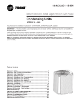
REFRIGERANT CIRCUIT
Liquid Pressure Too High
Liquid Pressure Too Low
Suction Pressure Too High
Suction Pressure Too Low
Liquid Refrig. Floodback TXV System
I.D. Coil Frosting
Compressor Runs Inadequate or No Cooling
ELECTRICAL
Compressor & O.D. Fan Do Not Start
Compressor Will Not Start But O.D. Fan Runs
O.D. Fan Won’t Start
Compressor Hums But Won’t Start
Compressor Cycles on IOL
I.D. Blower Won’t Start
SYSTEM FAULTS
P - Primary Causes S - Secondary Causes
P
P
P
S
S
PS
S
S
S
S
P
S
S
S
P
P
P
S
S
S
S
S
S
S
P
P
P
S
P
P
S
S
S
P
P
P
P
P
P
P
P
P
P
S
S
S
S
P
P
PP
P
S
S
PSPSS SSS
S
S
P
P
P
P
P
S
P
P
POWER SUPPL
Y
HIGH VOLTAGE W
IRING
COMPR. IOL
RUN CAPACITO
R
START CAPACITO
R
START RELAY
CONTACTOR CONTACTS
LOW VOLTAGE WIRING
CONTROL TRANSFO
RMER
CONTACTOR COIL
LOW VOLTAGE FUSE
STUCK C
OMPRESSO
R
INEFFICIENT CO
MPRESSO
R
REFRIGERANT U
NDERCHARG
E
REFRIGE
RANT OVERCHARGE
EXCESSIVE EVAP. LO
AD
NONCONDENSABLES
RESTRICTED O.
D
. AIRFLOW
O.D. AIR RECI
R
CULATION
TXV STUCK OPEN
SUPERHEAT
RESTRICTED
I.D.
AIRFLOW
REF. CIRCUIT RESTRICTIO
NS
O.D. FAN SPEED SWITCH
TROUBLESHOOTING CHART — WHAT TO CHECK

18-AC71D1-5 5
Installer’s Guide
Notes:
1. Be sure power supply agrees with equipment nameplate.
2. Power wiring and grounding of equipment must comply with local codes.
3. Low voltage wiring to be No. 18 AWG minimum conductor.
4. ODT-B must be set lower than ODT-A.
5. If outdoor thermostats (ODT) are not used, connect W1 to W2 and W3.
LEGEND
FACTORY WIRING
FIELD WIRING
PRINTED FROM B152901 P02
PRINTED FROM B152903 P02
NOTE
*
*
W2 present only on 2 stage
thermostat and furnace

6 18-AC71D1-5
Installer’s Guide
The Trane company has always recommended installing
Trane approved matched indoor and outdoor systems.
All Trane split systems are ARI rated with only TXV indoor
systems.
The benefits of installing approved indoor and outdoor split
systems are maximum efficiency, optimum performance and
the best overall system reliability.
The following charging methods are therefore
prescribed for systems with indoor TXVs.
1. Subcooling (in the cooling mode) is the
only recommended method of charging
above 55°F ambient temperatures.
2. For best results - the indoor temperature
should be kept between 70°F to 80°F. Add
system heat if needed.
3. At start-up, or whenever charge is
removed or added, the system must be
operated for a minimum twenty (20)
minutes to stabilize before accurate
measurements can be made.
4. Measure Liquid Line Temperature and
Refrigerant Pressure at service valves.
5. Determine total refrigerant line length,
and height (lift) if indoor section is above
the condenser.
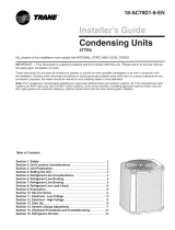
6. Determine the Design Subcool Charging
Temperature from the unit nameplate.
7. Locate this value in the appropriate
column of the Subcooling Charging Table.
Locate your liquid line temperature
in the left column of the table, and the
intersecting liquid line pressure under
your nameplate subcool value column.
Add refrigerant to raise the pressure to
SUBCOOL CHARGING TABLE CORRECTIONS FOR LINE LENGTH AND RISE
60
50
40
30
25
Add 10 psig to Subcool Charging Table Pressure
20
15
Use Design Subcool Value from Table
10
0
Subtract 10 psig from S.C. Table Pressure
10 20 25 30 40 60 80
TOTAL REFRIGERANT LINE LENGTH (FEET)
REFRIGERANT
LINE LIFT (FEET)
8910 11 12 13 14
55 179 182 185 188191 195 198
60 195 198 201 204208 211 215
65 211 215 218 222225 229 232
70 229 232 236 240243 247 251
75 247 251 255 259263 267 271
80 267 271 275 279283 287 291
85 287 291 296 300304 309 313
90 309 313 318 322 327 331 336
95 331 336 341 346 351 355 360
100 355 360 365 370 376 381 386
105 381 386 391 396 402 407 413
110 407 413 418 424 429 435 441
115 435 441 446 452 458 464 470
120 464 470 476 482 488 495 501
125 495 501 507 514 520 527 533
R-410A REFRIGERANT CHARGING CHART
Refer to Service Facts or
Installer's Guide for charging method.
LIQUID
TEMP
(
˚
F)
DESIGN SUBCOOLING (
˚
F)
LIQUID GAGE PRESSURE (PSI)
From Dwg. D154557P01 Rev. 2
match the table, or remove refrigerant to lower the
pressure. Again, wait twenty (20) minutes for the
system conditions to stabilize before adjusting charge
again.
8. When system is correctly charged, you can refer to
System Pressure Curves (in Service Facts) to verify
typical performance.

18-AC71D1-5 7
Installer’s Guide
4TTR3 OUTLINE DRAWING
From Dwg. D152898
FIG. A C D E F G H J K
4TTR3018A 3 1 832 (32-3/4) 829 (32-5/8) 756 (29-3/4) 1/2 3/8 143 (5-5/8) 92 (3-5/8) 210 (8-1/4) 79 (3-1/8) 508 (20)
4TTR3024A 3 1 832 (32-3/4) 829 (32-5/8) 756 (29-3/4) 5/8 3/8 143 (5-5/8) 92 (3-5/8) 210 (8-1/4) 79 (3-1/8) 508 (20)
4TTR3030A 3 1 832 (32-3/4) 829 (32-5/8) 756 (29-3/4) 3/4 3/8 143 (5-5/8) 92 (3-5/8) 210 (8-1/4) 79 (3-1/8) 508 (20)
4TTR3036B 3 1 933 (36-3/4) 829 (32-5/8 756 (29-3/4) 3/4 3/8 143 (5-5/8) 92 (3-5/8) 210 (8-1/4) 79 (3-1/8) 508 (20)
4TTR3042A 4 1 841 (33-1/8) 946 (37-1/4) 870 (34-1/4) 3/4 3/8 152 (6) 98 (3-7/8) 219 (8-5/8) 86 (3-3/8) 508 (20)
4TTR3048A 4 1 841 (33-1/8) 946 (37-1/4) 870 (34-1/4) 7/8 3/8 152 (6) 98 (3-7/8) 219 (8-5/8) 86 (3-3/8) 508 (20)
4TTR3060A 4 1 1045 (41-1/8) 946 (37-1/4) 870 (34-1/4) 7/8 3/8 152 (6) 98 (3-7/8) 219 (8-5/8) 86 (3-3/8) 508 (20)

Trane
www.trane.com
Trane has a policy of continuous product and product data improvement and it reserves the right to change
design and specications without notice.
Installer’s Guide
NOTE:
For model base size,
see table on page 7.
Note: All dimensions are
CHECKOUT PROCEDURE
After installation has been completed, it is recommended that the entire system be checked against the following list:
1. Refrigerant Line, Leak checked ................................. [ ]
2. Suction Lines and Fittings properly insulated.......... [ ]
3. Have all Refrigerant Lines been secured and
isolated properly? ........................................................ [ ]
4. Have passages through masonry been sealed?
If mortar is used, prevent mortar from coming
into direct contact with copper tubing ....................... [ ]
5. Verify tightness of all electrical connects .................. [ ]
6. Observe outdoor fan during on cycle for clearance
and smooth operation ................................................. [ ]
7. Indoor coil drain line drains freely. Pour water
into drain pan .............................................................. [ ]
8. Supply registers and return grilles open and
unobstructed ............................................................... [ ]
9. Return air filter installed ........................................... [ ]
10. Thermostat thermometer is accurate. Check
against a reliable thermometer. Adjust per
instructions with thermostat ..................................... [ ]
11. Is correct speed tap being used?
(Indoor blower motor) ................................................. [ ]
12. Operate complete system in each mode to
insure safe operation. ................................................. [ ]
From Dwg. 21D152637 Rev. 1
04/09
/