Page is loading ...

REV 2 - 1103150807
L-C2-333
1
09-41
SAFETY WARNINGS & CODES
Important: READ THESE INSTRUCTIONS CAREFULLY BEFORE STARTING INSTALLATION
DANGER
IF YOU SMELL GAS:
1. Shut off the gas to the appliance.
2. Extinguish any open fl ame.
3. Open lid.
4. If odor continues, keep away from the
appliance, and immediately call your
gas supplier or fi re department.
WARNING
1. Do not store or use gasoline or other
fl ammable vapors and liquids in the
vicinity of this or any other appliance.
2. A propane cylinder not connected for use
shall not be stored in the vicinity of this
or any other appliance.
Robert H. Peterson Co. • 14724 East Proctor Avenue, • City of Industry, CA 91746
CODE AND SUPPLY REQUIREMENTS: This
power burner must be installed in accordance with
local codes and ordinances, or, in the absence of
local codes, with either the latest National Fuel Gas
Code (ANSI Z223.1/NFPA 54), and Natural Gas and
Propane Storage and Handling Installation Code
(CSA-B149.1).
This appliance and its individual shutoff valves must
be disconnected from the gas supply piping system
when testing the system at pressures in excess of
½ psig (3.5 kPa).
This appliance must be isolated from the gas supply
piping system by closing its individual manual
shutoff valves during any pressure testing of the
gas supply system at pressures up to and including
½ psig (3.5 kPa).
All electrical outlets in the vicinity of the power
burner must be properly grounded in accordance
with local codes or, in the absence of local codes,
with the National Electrical Code, ANSI/NFPA
70, or the Canadian Electrical Code, CSA C22.1,
whichever is applicable.
Keep all electrical supply cords and fuel supply
hoses away from any heated surface.
WARNING
Improper installation, adjustment, alteration,
service, or maintenance can cause injury or
property damage. Refer to this manual. For
assistance or additional information consult
a qualifi ed professional installer, service
agency, or the gas supplier.
Certifi ed to: ANSI Z21.58a-2008
CSA 1.6a-2008
INSTALLER: Leave these instructions with consumer.
CONSUMER: Retain for future reference.
INSTALLATION AND OPERATING
INSTRUCTIONS
POWER BURNER
diamond series

REV 2 - 1103150807
L-C2-333
3
TABLE OF CONTENTS
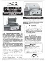
PRODUCT DATA TABLE
Table 1 - Product Data Table
Note: The hanger requires 2"
(5.1 cm) of countertop
on each side and back to
support the unit.
Specifi cation Value
Counter opening height* 12" (30.5 cm)
Counter opening width* 19" (48.3 cm)
Counter opening depth* 18 3/4" (47.6 cm)
BTU 60,000 (17.6 kw)
Natural gas orifi ce left #30 (3.261mm)
Natural gas orifi ce right #46 (2.055 mm)
Propane gas orifi ce left #50 (1.778 mm)
Propane gas orifi ce right #1.25
*Note: If using an insulating liner
(part number 3278-50)
consult liner instructions for
counter cut-out dimensions.
ELECTRICAL SAFETY
To protect against electric shock, do not immerse cord or plugs (if equipped) in water or other liquid;
Unplug from the outlet (if applicable) when not in use and before cleaning. Allow to cool before putting on or
taking off parts;
Do not operate any outdoor cooking gas appliance with a damaged cord, plug, or after the appliance malfunctions
or has been damaged in any manner. Contact the manufacturer for repair;
Do not let the cord hang over the edge of a table or touch hot surfaces;
Do not use an outdoor cooking gas appliance for purposes other than intended;
When connecting, fi rst connect plug to the outdoor cooking gas appliance then plug appliance into the outlet;
Use only a Ground Fault Interrupter (GFI) protected circuit with this outdoor cooking gas appliance;
Never remove the grounding plug or use with an adapter of 2 prongs.
Use only extension cords with a 3 prong grounding plug, rated for the power of the equipment, and approved for
outdoor use with a W-A marking.
3 PRODUCT DATA TABLE
4 PARTS LIST
5 PLANNING FOR INSTALLATION OF YOUR POWER BURNER
5 WHERE TO INSTALL THE POWER BURNER
5 GAS PLUMBING REQUIREMENTS FOR YOUR SLIDE-IN POWER BURNER
5 ENSURING PROPER COMBUSTION AIR AND COOLING AIR FLOW
5 GAS SUPPLY PLUMBING REQUIREMENTS
5 GAS SUPPLY AND MANIFOLD PRESSURES
5 GAS SUPPLY PRESSURE TESTING
7 SAFE USE & MAINTENANCE OF PROPANE GAS CYLINDERS
8 INSTALLING YOUR FIRE MAGIC POWER BURNER
8 CHECK FUEL ORIFICES FOR PROPER SIZE
8 POSITION THE BURNER FOR OPERATION
8 CONNECT THE GAS SUPPLY
9 POWER SUPPLY FOR IGNITION AND LIGHTED KNOBS
10 POWER SUPPLY (MULTIPLE ACCESSORY UNITS)
11 INSTALL THE FLAME COLLIMATOR
11 REMOVE THE CONTROL PANEL TO CHECK RATING PLATE
11 ADJUST THE AIR SHUTTERS
13 LIGHTING (IGNITION) INSTRUCTIONS
13 SHUTTING OFF THE UNIT
14 CARE & CLEANING
15 CHECKING AND CONVERTING GAS TYPE
15 CHECKING AND CONVERTING THE REGULATOR
16 POWER BURNER NOTES PAGE
17 TROUBLESHOOTING
18 WARRANTY

REV 2 - 1103150807
L-C2-333
4
PARTS LIST
1
3
2
5
6
4
9
7
8
13
10
15
TOOLS REQUIRED FOR INSTALLATION:
• #2 (Medium) Phillips screwdriver
• Two medium size adjustable wrenches or pliers
•
3
/
8
" wrench or socket screwdriver
• Pipe joint compound resistant to all gasses
Replacement parts can be ordered
from your local Fire Magic dealer.
11
Item Part No. Description
1. 3278-06 Cover
2. 3545 Grid, porcelain cast iron (black)
or 3545-S Grid, stainless steel rod
3. 3278-09 Flame collimator (stir fry ring)
4. 3278-01B Burner assembly, brass
5. 3048-03-2 Spring air shutter (2)
6. n/a Air shutter (2) inc. w/ burner
7. 3001-# Orifi ces (2) (see table 1)
8. 4199-52 Electrode kit w/ground wire
9. 3278-14 Valve manifold
10. 24182-42 Control knob, small (inner burner)
11. 24182-41 Control knob, large (outer burner)
12. 24182-44 Lighted bezel assembly, small
13. 24182-43 Lighted bezel assembly, large
14. 23278-09 Control panel
15. 3085 Drip tray assembly
16. 24182-46 Light switch
17. 23278-12 Extension wire kit (not shown)
18. 3036 36" fl ex connector
12
16
14
18

REV 2 - 1103150807
L-C2-333
5
WARNING
The power burner must be installed in masonry
or other type of fi reproof surround. The unit is not
insulated and therefore must be installed or placed
with 18
"
(45.7 cm) of side and back clearance from
unprotected combustible materials such as wood,
plastic, or stucco with wood framing.
Do not install this unit under unprotected fl ammable
surfaces. Do not install or use this appliance inside a
building, garage, or any other enclosed area. It must
not be used in or on recreational vehicles or boats.
This is a slide-in unit designed to fi t into open-front
enclosures. Control panel of the unit is removable for
gas hookup, servicing and burner adjustment. Control
panel must remain removable after you install the unit.
Important: The hanger requires 2" (5.1 cm) of
countertop on each side and back to
support the unit.
Note: We recommend you build the enclosure for
the power burner 6"-12" (15.2 cm- 30.5 cm)
LOWER than your countertop (see Fig. 5-2).
This will ensure a safer environment when
using tall cooking pots like the turkey fryer,
which can hold 40 lbs of hot oil.
PLANNING FOR INSTALLATION OF YOUR POWER BURNER
Note: This unit should be installed so that it can be
removed at a later date if factory service is
required. Any protrusion into the power burner
enclosure may prevent the unit from sliding
into place (see GAS SUPPLY PLUMBING
REQUIREMENTS).
ENSURING PROPER COMBUSTION AIR AND
COOLING AIR FLOW
You must maintain proper air fl ow for your Fire Magic
power burner to perform as it was designed (Fig. 5-1). If
airfl ow is blocked, overheating and poor combustion will
result. Make sure not to block the 1" (2.5 cm) front air
inlet along the bottom of the control panel or more than
75% of the support grid surface with pans or griddles.
Note: The 1" (2.5 cm) front air space allows access
to the drip tray.
EXHAUST REMOVAL
If installed under a patio roof, the cooking grid area
should be fully covered by a chimney and exhaust hood.
An exhaust fan with a rating of up to 1,000 CFM (472
liters per second) may be
necessary to effi ciently
remove smoke and other
cooking by-products
from the covered area.
Installation in fully
enclosed patio areas is
not recommended.
Fig. 5-1 - Ventilation Diagram
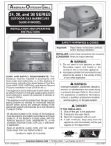
GAS SUPPLY PLUMBING REQUIREMENTS
Rigid
1
/
2
" (1.3 cm) or
3
/
4
" (.75 cm) black steel pipe, or local
code approved pipe for temperatures up to 800°F (427°C),
is required to conduct the gas supply into the enclosure
opening for connection to the unit. Do not use a rubber
hose within the enclosure for the power burner. Apply
only joint compounds that are resistant to all gasses on all
male pipe fi ttings. Make sure to tighten every joint securely.
The gas supply pipe should terminate below the power
burner so fi nal connection can be made with an approved
fl ex connector.
Install the gas line stub
at least 1
1
/
2
" (3.8 cm)
away from the side
walls and 1
" (2.54 cm)
from the back wall,
but within 5
" (12.7
cm) of the back wall,
as illustrated by the
shaded area in Fig.
5-2.
Note: An external
valve (with
a removable
key) in the
gas line is necessary for safety when your
power burner is not in use. It also provides for
convenient maintenance.
You will need a C.S.A. approved stainless steel flex
connector to bring the gas supply from the gas line stub to
the regulator. A
1
/
2
" (1.27 cm) x 36" (91.4 cm) or 24" (61
cm) fl ex connector with
1
/
2
" (1.27 cm) fl are to
1
/
2
" (1.27 cm)
pipe adapter on one end, and a
1
/
2
" (1.27 cm) fl are female
fi tting on the other end is suitable for most installations.
CAUTION: Use only stainless steel fl ex connectors
that are C.S.A. listed. A rubber or plastic
connector will rupture or leak, resulting in
an explosion or serious injury if used inside
the power burner enclosure.
Important: See page 7 for the proper venting of the
enclosure.
GAS SUPPLY AND MANIFOLD PRESSURES
For natural gas - Normal 7" (17.8 cm) water column (w.c.),
Minimum 3
1
/
2
" (8.9 cm) w.c., Maximum 10
1
/
2
" (26.7 cm) w.c.
For propane gas Normal 11" (27.9 cm) (w.c.), Minimum 8"
(20.3 cm) (w.c.), Maximum 13" (33 cm).
GAS SUPPLY PRESSURE TESTING
This appliance and its individual shutoff valves must be
disconnected from the gas supply piping system when
testing the system at pressures in excess of
1
/
2
psig (3.5 kpa).
This appliance must be isolated from the gas supply piping
system by closing its individual manual shutoff valves during
any pressure testing of the gas supply system at pressures
up to and including
1
/
2
psig (3.5 kpa).
GAS PLUMBING REQUIREMENTS FOR YOUR SLIDE-IN POWER BURNER
19”
1”
18 3/4”
1 1/2”
1 1/2”
4”
12”
12”
Fig. 5-2 - Gas stub diagram
Optional 6 - 12" (15.3 - 30 cm) Drop
WHERE TO INSTALL THE POWER BURNER
IMPORTANT: THIS POWER BURNER IS FOR
OUTDOOR USE ONLY.

7
U
L
Fig. 7-1 Type I Acme thread quick coupler
Pressure
relief
valve
QCC
Type 1
valve
Brass Acme
thread fi tting
Liquid level
indicator
(optional)
Hand nut with Acme
thread
Regulator
Vent
Hose
Hand wheel
The use of pliers or a wrench should not be necessary. Only
cylinders marked “propane” may be used.
To disconnect: Turn the hand nut counterclockwise until
detached (Fig. 7-1).
Important: Before using the unit, and after each time the
cylinder is removed and reattached, check
the hose for wear (see a.) and check all
connections for leaks. Turn off the unit valves
and open the main cylinder valve, then check
connections with soapy water. Repair any
leaks before lighting the unit.
CAUTION: Always turn the propane cylinder main valve
off after each use, and before moving the unit
and cylinder or disconnecting the coupling.
This valve must remain closed and the
cylinder disconnected while the appliance
is not in use, even though the gas fl ow is
stopped by a safety feature when the coupler
is disconnected.
Carefully inspect the hose assembly each time before the
gas is turned on. A cracked or frayed hose should be replaced
immediately.
If the appliance is stored indoors, the cylinder must be
disconnected and removed. Disconnected
cylinders must be
stored outdoors, out of the reach of children, with threaded
valve plugs tightly installed, and must not be stored in a
building, garage, or any other enclosed area.
FOR YOUR SAFETY
a. DO NOT store a spare propane-gas cylinder under or
near this appliance.
b. NEVER fi ll the cylinder beyond 80-percent full.
c. IF THE INFORMATION IN a. AND b. IS NOT FOLLOWED
EXACTLY, A FIRE CAUSING DEATH OR SERIOUS
INJURY MAY OCCUR.
IMPORTANT FOR YOUR SAFETY
READ AND FOLLOW ALL WARNINGS PROVIDED WITH THE PROPANE-GAS CYLINDER.
When operating this appliance with a propane-gas cylinder, these instructions and warnings MUST be observed.
FAILURE TO DO SO MAY RESULT IN A SERIOUS FIRE OR EXPLOSION.
CYLINDER/CONNECTOR REQUIREMENTS
a. Propane-gas cylinders, valves, and hoses must be
maintained in good condition and must be replaced if
there is visible damage to either the cylinder or valve. If the
hose is cut or shows excessive abrasion or wear, it must
be replaced before using the gas appliance (see e.).
b. This unit, when used with a cylinder, should be connected
to a standard 5-gallon (20 lb.) propane-gas cylinder
equipped with an OPD (Overfi ll Prevention Device).
The OPD has been required on all cylinders sold since
October 1,1998, to prevent overfi lling.
c. Cylinder dimensions should be approximately 12" (30.5
cm) in diameter and 18" (45.7 cm) high. Cylinders must
be constructed and marked in accordance with the
Specifi cations for Propane Gas Cylinders of the U.S.
Department of Transportation (D.O.T.) or the National
Standard of Canada, CAN/CSA-B339, Cylinders,
Spheres, and Tubes for Transportation of Dangerous
Goods.
d. The cylinder used must include a collar to protect the
cylinder valve, and the cylinder supply system must be
arranged for vapor withdrawal.
e. The pressure regulator and hose assembly (Fig. 7-1)
supplied with this outdoor-cooking gas appliance must
be used. Original and replacement pressure regulator
and hose assemblies must be those specifi ed by the
manufacturer for connection with a cylinder connecting
device identifi ed as Type I by the ANSI Z 21.58-2005/CGA
1.6-2005 (see PARTS LIST for ordering information).
f. The propane-gas cylinder valve must be equipped with a
cylinder connection coupling device, described as Type
I in the standard defi ned in paragraph e. above. This
device is commonly described as an Acme thread quick
coupler.
g. If the propane-gas cylinder comes with a dust plug, place
the dust cap on the cylinder valve outlet whenever the
cylinder is not in use.
QUICK COUPLER OPERATION
To connect the regulator/hose assembly to the propane-
gas cylinder valve fi tting: Press the hand nut on the regulator
over the Acme thread fi tting on the cylinder valve. Turn the hand
nut clockwise to engage the threads and tighten until snug.
ENCLOSURE REQUIREMENTS
FOR YOUR SAFETY, you must provide the openings listed below for drainage, replacement air, and cross-ventilation
of any storage area exposed to possible leakage from gas connections, the unit, or propane cylinders:
One side of the gas cylinder enclosure left completely open to the outside OR by providing four (4) ventilation
openings. Two (2) openings are to be at the cylinder valve level (approx. 16" [40.6 cm] above the fl oor) and on
opposite walls of the enclosure. Two (2) more openings must be at the fl oor level on opposite sides of the enclosure.
The fl oor-level openings must start at the fl oor and shall extend no higher than 5" (12.7 cm) above the fl oor. Each
opening must have a minimum of 10 sq. in. (64.5 cm
2
) of free area. To achieve the proper ventilation, you may drill
a series of holes, omit the grout from masonry joints, or replace a brick with a hardware cloth screen. If the fl oor
in the cabinet is raised and the space beneath the cabinet is open to the outside, the lower ventilation openings
may be in the fl oor.
Consult your gas supplier for ventilation and regulator requirements when connecting to a household propane supply.
e. The pressure regulator and hose assembly used must
match the specifi cation for Type I by ANSI Z 21.58-2005/
CGA 1.6-2005 (see Fig. 7-1).
SAFE USE & MAINTENANCE OF PROPANE GAS CYLINDERS

8
Perform the following checks before installing your
power burner:
CHECK FUEL ORIFICES FOR PROPER SIZE
1. Your Fire Magic power burner is equipped with
fuel orifi ces for natural gas, unless otherwise
indicated. To change the gas type, you must install
different orifi ces to avoid hazardous overheating.
(Refer to Table 1 for the proper orifi ce size)
IMPORTANT: When converting orifi ces for different
gas type, the regulator must also
be converted for the new gas type.
Reference the REMOVE THE
CONTROL PANEL and CONVERTING
THE REGULATOR sections.
2. Remove the cooking grid. Grip the flame
collimator and remove it by compressing the ring
slightly front to back and lifting the compressed
end upward. Reference the fi gure in the INSTALL
THE FLAME COLLIMATOR section.
3. Check the orifi ce size by lifting the burner up and
out of the locator hole and pulling it away from
the orifi ces. The orifi ce size is stamped on the
orifi ce face. Be sure not to lose the air shutter or
air shutter spring which may become detached
when the burner is removed.
POSITION THE BURNER FOR OPERATION
1. After checking orifi ce size install the air shutter
spring and the air shutter over the orifi ce holder
fi tting, between the burner and the heat shield,
in the order and position shown in Fig. 8-1.
2.
Carefully place the burner stud back in the locator
hole so that the brass orifi ce and orifi ce holder
fi ttings project into the burner air venturi. When
the burner stud fi ts in the locator hole the orifi ce
is in alignment.
INSTALLING YOUR FIRE MAGIC POWER BURNER
Fig. 8-1
Burner air venturi
Orifi ce
CONNECT THE GAS SUPPLY
CAUTION: Use only C.S.A. listed stainless-steel fl ex
connectors within the enclosure.
WARNING
A rubber or plastic connector will rupture or leak,
resulting in an explosion or serious injury if used
inside the appliance enclosure.
1. Run the attached fl ex connector routed under
the left side of the unit out of the enclosure and
to the gas stub.
2. Turn OFF the gas supply at the source. Then
connect the
1
/
2
" pipe adapter fi tting supplied
with the stainless-steel fl ex connector to the
gas-supply stub. Use pipe joint compound that
is resistant to all gasses on the male pipe fi tting
and tighten securely. DO NOT use pipe joint
compound to connect fl are fi ttings.
3. Turn all burner control knobs to the OFF position.
Turn the gas supply on. Then carefully check all
gas connections for leaks with a brush and half-
soap/half-water solution before lighting. NEVER
USE A MATCH OR OPEN FLAME TO TEST
FOR LEAKS.
4.
Close the dedicated gas-supply shut-off valve,
then slide the unit into place. Be sure not to
pinch, kink, or damage the gas connector line.
Fig. 8-2 Sliding into place
Fig. 8-4
TO GAS SUPPLY

9
POWER SUPPLY FOR IGNITION AND
LIGHTED KNOBS
CAUTION: Improperly connected wires will cause
damage to the unit and may result
in property damage and/or personal
injury.
The unit comes with a 6' wire extension to retrieve
power from a separately purchased Echelon grill.
Echelon grills are equipped with power supply
boxes, which can supply power to the power burner.
Alternatively; an optional power supply box may be
ordered and installed to individually power this unit.
To install using the wire extension:
Locate the power supply box inside of the island
enclosure. Disconnect the power cord.
1. Disconnect the grill (male) molex connection
from the master switch harness. Disconnect the
grill ground wire from the power supply box. (See
Fig. 9-1.)
2. Locate the side of the power burner wire extension
that has two molex connections. Connect the
extension (male) molex connection to the master
switch (female) molex connection. Connect the
extension (female) molex connection to the grill
(male) molex connection. (See Fig. 9-2.)
3. Connect the 2 extension ground wires to the grill
and power supply box ground wires AS SHOWN
in Fig. 9-3.
INSTALLING YOUR FIRE MAGIC POWER BURNER (Cont.)
4. Connect the opposite end of the extension to
the power burner, as shown in Fig. 9-4 (molex
and ground wire connections).
To install using a power supply box:
1. Install the power supply box at least 12 inches
below the bottom of the power burner.
2. Fasten the power supply box to the inside of
the enclosure, making sure the vent holes are
not blocked.
3. Connect the power supply box to the power
burner, as shown in Fig. 9-5 (molex and ground
wire connections).
4. Plug the power cord into a properly wired
and inspected GFI receptacle (not included).
Use a heavy duty grounded extension cord if
necessary.
Fig. 9-2
Power burner
wire extension
CONNECT
Fig. 9-1
Master switch
harness
Grill molex
connection
Power
supply box
Grill ground wire
DISCONNECT
Fig. 9-3
CONNECT
Fig. 9-4
Wires from
power burner
CONNECT
Wire
extension
Fig. 9-5
Wires from power burner
CONNECT
Power
supply box
Power cord

10
POWER SUPPLY (MULTIPLE ACCESSORY UNITS)
The previous section covers in detail how to individually connect this accessory unit to an Echelon grill power
supply box. If multiple accessory units are to be installed, the following diagrams will assist in their installation.
INSTALLING YOUR FIRE MAGIC POWER BURNER (Cont.)
Grill Left Install
Grill Center Install
Grill (master switch)
wire harness
Grill (master switch)
wire harness
Power supply box
Each accessory unit equipped with one wire extension
Power supply box
Each accessory unit equipped with one wire extension

11
INSTALL THE FLAME COLLIMATOR
1. Place the fl ame collimator over the burner with
the tabs and cutouts resting on the inner liner
shelf, as shown in Fig. 11-1. Flex the front of the
collimator towards the burner until the cut outs fi t
down around the collimator support. This will lock
your collimator into place. The fl ame collimator
acts as a barrier for windy conditions and creates
higher BTU concentration in the cooking grid.
2. When using a wok for stir fry cooking, remove
the grid and the wok will be supported by the
collimator.
REMOVE THE CONTROL PANEL TO CHECK
RATING PLATE
The control panel may be removed to access the
rating plate and check for the gas type of your power
burner.
1. Turn off the gas shutoff valve.
Pull off the control
knobs. Slowly lift away the lighted bezels to clear
the valve stems, and carefully disconnect the wires
found on the back of the bezels (use your fi ngernail).
See Fig. 11-1. Unscrew and remove the control
panel screws and washers.
INSTALLING YOUR FIRE MAGIC POWER BURNER (Cont.)
2. Carefully lift the control panel away from the
frame.
3. Check the rating plate for gas type.
Important: If converting the gas type, see the
CHECKING AND CONVERTING
THE REGULATOR section before
replacing the control panel.
4. Replace the control panel. Reconnect the
bezels and secure in place. Replace the control
knobs.
ADJUST THE AIR SHUTTERS
Power burner air shutter(s) are located on the necks
of the power burner as shown in Fig. 11-2.
CAUTION: DO NOT handle a hot burner without
adequate hand protection.
To adjust the air shutters:
1. See step 2 under
the CHECK FUEL
ORIFICES FOR
PROPER SIZE
section.
2. Lift the back of the
burner upward so
that the burner stud
in the bottom back
clears the locator
hole in the burner rest.
3. Move the burner back away from the front of the
power burner while continuing to lift the back
upward so that it clears the rear fi rewall.
4. Turn the shutter to the desired opening size
and replace the burner to test the effect on the
fl ame (see LIGHTING INSTRUCTIONS).
Burner flames should burn evenly (mostly
blue). A proper fl ame pattern will ensure safe
operation and optimal performance.
Fig. 11-2
Air shutters
Fig. 11-1
Bezel
removed
Carefully
disconnect
Fig. 11-1 Placing the fl ame collimator
Cut
outs
Flame
Collimator
Collimator support
Collimator support
T abs

13
SHUTTING OFF THE UNIT
To shut off the unit, depress each valve control knob
and, and while pressing turn it clockwise to the OFF
position.
Always close the valve from the gas supply after each
use of the unit.
ELECTRONIC LIGHTING
Note: Electronic lighting requires an installed 9-volt
battery with a good charge.
1. Open lid(s) or remove cover(s) from burner(s) to be lit.
2. Turn all gas control knob(s) to their OFF position(s).
3. Turn on the gas at its source.
Note: DO NOT
turn on more
than one valve at
a time for either
electronic or
manual lighting.
4. Depress the desired control knob, and while pressing
turn it counterclockwise to the HI LIGHT position.
Once the burner lights, release the control knob.
CAUTION: If a burner does not light within fi ve (5)
seconds of turning on the control knob,
depress the knob and turn it to the OFF
position. WAIT FIVE (5) MINUTES
before repeating step 4. If you smell
gas, follow the instructions on the cover
of this manual. If the burners still do not
light after several attempts, refer to the
instructions for manual lighting.
5. Repeat step 4 for each additional burner to be lit.
WHEN USING A PORTABLE PROPANE TANK
Propane tanks are equipped with a safety shutdown
device that may cause low or no gas pressure/fl ame
at the burners if operating and lighting instructions
are not followed exactly (See important note in the
TROUBLESHOOTING section for more details.)
MANUAL LIGHTING
CAUTION: Always wait fi ve (5) minutes for gas to
clear after any unsuccessful lighting
attempt.
1. Follow steps 1 through 3 (left).
2. Insert either a burning long-barrel butane lighter or
a burning long-stem match through the cooking grid
opening to the top of the lighting tube. (Fig. 13-2).
For backburners, hold the flame against the
perforated material of the backburner.
For sideburners, hold the fl ame against the burner.
3. While holding the match or lighter fl ame at the top
of the lighting tube or next to the burner (sideburner
and backburner only), depress the desired control
knob and while pressing turn it counterclockwise to
the HI LIGHT position. Remove the lighter or match
when the burner lights, and release the control
knob.
4. If the burner does not light, immediately depress
the knob and turn the valve to OFF. WAIT FIVE
(5) MINUTES before repeating steps 2 through 4
of the MANUAL LIGHTING instructions.
Read all instructions before lighting, and follow these instructions each time you light the unit.
Fig. 13-2 - Manual lighting
Lighter
Lighting
tube
CAUTION: Always wait fi ve minutes for gas to clear
after any unsuccessful lighting attempt.
WARNING: DO NOT put hand directly above the burner
when lighting but off to the side as shown
(Fig. 13-2).
1. Follow steps 1 through 3 (left).
2a. Insert either a burning long-barrel butane lighter, a
burning long-stem match, or a burning match held by
a wire extension holder through the cooking grids to
the desired burner to be lit (Fig.
13-2). With the fl ame
still next to the burner, depress the corresponding
control knob (outer burner- right knob, inner burner-
left knob), and while pressing turn it counterclockwise
to the HI LIGHT position. Remove the lighter or match
when the burner lights, and release the control knob.
2b. To manually light the second burner, after step 2a
has been followed, depress the corresponding control
knob, and while pressing turn it counterclockwise to the
HI LIGHT position. The second burner will light from the
fl ame of the already lit burner. Release the control knob.
3. If the burner does not light, IMMEDIATELY turn the
burner control knob to the OFF position. WAIT FIVE
MINUTES before repeating steps 2 and 3 of the
MANUAL LIGHTING INSTRUCTIONS.
Outer
Burner
Control
Fig. 13-2 - Manual lighting
Outer
Burner
Control
Fig. 13-2 - Manual lighting
Fig. 13-1 - Control knob
OFF
HI
LIGHT
LOW
TO
TURN OFF
TO TURN ON
Read setting
here
HIGH to
LIGHT
Read setting here
(OFF position shown)
To Turn OFF
To Turn ON
Use
HI (high)
to light
Press
knob in
to turn
Gas Flow
Indicator
For your convenience and safety; when the
control knob is in the on position, the gas fl ow
indicator will change from blue to red. (Red
indicates gas fl ow.) See Fig. 13-1.
Note: Unit must be connected to 110VAC power for
electronic lighting.
LIGHTING (IGNITION) INSTRUCTIONS

14
Fig. 14-1 - Wipe with grain
PROTECTING YOUR APPLIANCE FROM THE
WEATHER
An optional heavy-duty cover will protect your
appliance’s fi nish and protect your investment. The
water repellent cover will protect your appliance
from the weather. Always cover your appliance
when not in use. (Allow to cool before covering.)
Please specify the model number and serial
number of your appliance when ordering a cover.
CARE AND CLEANING
APPLIANCE MUST BE COMPLETELY COOL WHEN
CLEANING. DO NOT SPRAY ANY CLEANER OR
LIQUIDS ON THE APPLIANCE WHEN HOT.
Stainless steel surfaces when exposed to
temperatures produced by the grilling process will
change color. The stainless steel will change color
from silver to brown and blue. This can be removed by
using Fire Magic Stainless Steel Cleaner (3581-1).
Clean your appliance by fi rst using Fire Magic
Barbecue and Grill Cleaner (part #3580-1) to
remove grease and dirt. Always wipe with the grain
(See Fig. 14-1). Next, use Fire Magic Stainless
Steel Cleaner (3581-1) to restore the stainless steel
color (Note: not for mirror fi nish). Finish by wiping
your appliance down using Fire Magic Polish Wipes
(3586-1). To clean the mirror panel (if applicable),
use a quality brand glass cleaner only, not any
of the cleaners mentioned above.
Clean your appliance at least once a month.
If your appliance is installed in a seaside (salt air) or
poolside (chlorine) location, it will be more susceptible
to corrosion and must be maintained/cleaned more
frequently. Do not store chemicals (such as chlorine
or fertilizer) near your stainless steel appliance.
Due to the nature of stainless steel, surface iron
oxide deposits may appear. Do not be alarmed –
these deposits are removable with stainless-steel
cleaner through prompt and periodic maintenance.
If not attended to promptly, permanent pitting may
occur.
Check and clean the burner ports and burner carry-
over slits for blockage at least annually by removing
the burner (see orifi ce changing instructions) and
visually inspecting the burner inlet for insects and
nests. A clogged burner can lead to a fi re in the
bottom of the appliance. (For Fire Magic grills use
Maintenance Kit part #MK-1.)
The inside of the appliance may be cleaned
periodically with oven cleaner if desired. Follow the
oven cleaner instructions for proper use.
Be careful not to get oven cleaner on the outside
surface of the appliance as it can permanently
damage the fi nish.
By following these recommendations, you will enjoy
the beauty and convenience of your appliance for
many years to come.
IMPORTANT
IN THE EVENT OF A GREASE FIRE,
IMMEDIATELY SHUT OFF THE MAIN GAS
VALVE TO THE GRILL. KEEP THE LID OPEN
AND ALLOW THE FIRE TO EXTINGUISH
ITSELF. A THOROUGH INSPECTION BY A
TRAINED SERVICE TECHNICIAN SHOULD
BE CONDUCTED BEFORE FUTURE USE OF
YOUR GRILL. THE SERVICE TECHNICIAN WILL
CHECK THE SYSTEM FOR GAS LEAKS AND
WILL CHECK ALL ELECTRICAL WIRING FOR
DAMAGE. ALL GAS LEAKS AND WIRING MUST
BE REPAIRED PRIOR TO FUTURE USE.
Wipe with grain
CARE & CLEANING

15
CHECKING AND CONVERTING GAS TYPE
This unit comes from the factory confi gured for
one type of gas, as marked on the label behind the
control panel.
Converting this unit to burn a different type of
gas requires a conversion kit from the factory.
The professional installer who converts this
unit to burn a different gas must perform the
following functions:
1. Change brass gas orifices (included at original
shipping) on each burner to match the new gas type
(see PRODUCT DATA TABLE, Table 1).
2. Switch the convertible gas regulator (included
at original shipping, located behind the control
panel) to match the new gas type (see below).
3. Plumb the unit to the new gas supply.
4. Apply a new label behind the control panel,
indicating the new gas the unit will burn (included
with conversion kit).
HAZARDOUS OVERHEATING WILL OCCUR
IF A NATURAL-GAS ORIFICE IS USED WITH
PROPANE GAS. IF YOU ARE NOT SURE IF THE
CORRECT ORIFICES ARE INSTALLED, OR IF AN
ORIFICE CHANGE IS NECESSARY, REFER TO
THE FOLLOWING INSTRUCTIONS.
CAUTION: Make sure the unit is at a safe
temperature and isolated from gas and
electrical supplies before beginning
the tasks outlined below.
Note: The cooler the unit, the greater the tolerances
between the stainless-steel parts, and
therefore the easier to disassemble and
reassemble parts of the unit.
CAUTION: For your safety, exercise caution and
use adequate hand protection (such
as gloves) when handling potentially
sharp sheet-metal parts.
THIS APPLIANCE REGULATOR IS RATED FOR
1
/
2
PSI MAXIMUM. IF YOUR GAS SUPPLY IS
GREATER THAN
1
/
2
PSI, AN ADDITIONAL REGULATOR MUST BE INSTALLED TO REDUCE
THE INPUT PRESSURE TO THE UNIT to
1
/
2
PSI OR LESS. SEE GAS-SUPPLY REQUIREMENTS
SECTION FOR PROPER GAS-SUPPLY PRESSURE.
CHECKING AND CONVERTING THE REGULATOR
Note: Each end of the plastic converter is engraved with either the letters “NAT”
or “L.P.” (propane) for the respective gasses. When the converter is in the
cap and the cap is held uppermost, the letters seen indicate the gas that
the regulator is set up for.
To convert the regulator from one gas to another, follow steps 1-4.
STEP 2:
Remove the converter (the
plastic stalk) by carefully
pulling it away from the center
of the cap (it will snap out of
its seating).
STEP 1:
Unscrew and remove the cap from the
regulator, extracting the converter.
Regulator: note the cap
on top
STEP 3:
Turn the converter around and
replace it carefully, into the
center of the cap (it will snap
into place). Check that you can
read the type of gas the unit is
set for.
STEP 4:
Replace the unit into the
regulator and screw down
until snug.
Read gas
type here
WARNING
WARNING

16
POWER BURNER NOTES PAGE
Please use this page to record any information about your power burner that you may want to have at hand.

17
PROBLEM POSSIBLE CAUSE CORRECTION
Ignition system
failure
1) Improper air shutter adjustment 1) Adjust air shutters.
2) Ignition wire disconnected 2) Replug wires into generator.
3) Low gas pressure 3) Adjust or replace battery.
4) Igniter switch malfunction 4) Contact dealer for replacement.
Insuffi cient heat
1) Improper air shutter adjustment 1) Adjust air shutters.
2) Using propane orifi ce for natural gas 2) Change orifi ces.
3) Low gas pressure/fl ame (natural) 3) Have gas company check the
operating pressure at the unit.
4) Low gas pressure/fl ame (propane) 4) Refill propane tank, or reset
propane tank safety*: Shut off all
valves (including propane tank) and
follow lighting instructions exactly.
Uneven heating
1) Burner ports partially blocked by debris 1) Remove burners and clean out ports.
2) Small spiders or insects in burner 2) Inspect burners for spider webs or
other debris that may block gas fl ow.
Burner goes out on
LOW
1) Valve “Low” setting needs
adjustment
1) Light burner on HIGH, immediately
turn to LOW setting. Remove
knob from valve and using a small
flat screwdriver, slowly turn the
adjustment screw in the stem,
a little at a time (30° to 45°), in
either direction, until the fl ame is
approximately
1
/
4
” in height from
burner ports.
Knob light(s) not
operating
1) Light switch off
2) Knob light(s) burned out
1) Turn light switch on
2) Contact dealer for replacement.
Rotisserie noisy
1) Rotisserie out of balance 1) Adjust counterbalance.
If you have trouble with the unit, please use this list to identify the problem. By trying one or more of the
solutions to the possible cause, you should be able to solve the problem. If this list does not cover your
present problem, or if you have other technical diffi culties with the unit, please contact your local dealer.
TROUBLESHOOTING
Note: *Propane tanks are equipped with a safety shutdown device that may cause low or no gas/fl ame
at the burners if operating and lighting instructions are not followed exactly. If you suspect the
propane tank safety shutoff is in effect, shut off all burner control valves and the propane tank
valve. Then read and follow the LIGHTING INSTRUCTIONS exactly. Lighting instructions are
located in the owner’s manual. If the problem persists, continue troubleshooting, or contact your
local dealer or distributor for assistance.

18
PLEASE KEEP A COPY OF YOUR SALES SLIP FOR PROOF OF PURCHASE
This warranty applies to the original purchaser and to single family residential use only. It commences from date of purchase, and is valid only with
proof of purchase.
This warranty does not cover parts becoming defective through misuse, accidental damage, electrical damage, improper handling, storage, and/or
installation. Product must be installed (and gas must be connected) as specifi ed in the instructions or operator’s manual, by a qualifi ed professional
installer. Accessories, parts, valves, remotes, etc., when used must be Peterson Co. product.
This warranty does not apply to rust, corrosion, oxidation, or discoloration, unless the affected component becomes inoperable. It does not cover
labor or labor-related charges.
This warranty specifi cally excludes liability for indirect, incidental, or consequential damages. Some states do not allow the exclusion or limitation of
incidental or consequential damages, so the above exclusion may not apply to you. This warranty gives you specifi ed legal rights, and you may have
other rights that may vary from state to state.
For additional information regarding this warranty, or to place a warranty claim, contact the R.H. Peterson dealer where the product was purchased.
TO REGISTER YOUR PRODUCT ONLINE GO TO: WWW.RHPETERSON.COM,
AND CLICK ON PRODUCT REGISTRATION. THANK YOU FOR YOUR PURCHASE.
LIFETIME WARRANTY - Fire Magic
®
cast stainless-steel burners, stainless-steel rod cooking grids, and stainless-steel housings are
warranted for as long as you own your Fire Magic
®
grill.
FIFTEEN-YEAR WARRANTY - Fire Magic
®
cast brass burners, brass valves, backburner assemblies (except ignition parts), and
manifold assemblies are warranted for 15 years from the date of purchase of your Fire Magic
®
grill.
THREE-YEAR WARRANTY - Fire Magic
®
sideburners and all other Fire Magic
®
grill components (except ignition and electronic
parts) are warranted for three (3) years from the date of purchase of your Fire Magic
®
grill.
Fire Magic
®
ignition systems (excluding batteries), electronic components (including lights and thermometers), and accessories are
warranted for one (1) year from date of purchase.
Robert H. Peterson Co. • 14724 East Proctor Avenue • City of Industry, CA 91746Robert H. Peterson Co. • 14724 East Proctor Avenue • City of Industry, CA 91746
Quality Check Date:_________________
Burner Orifi ces Nat. L.P. Leak Test: ___________ Model#: ___________________
Main: ____ ____ Burn Test: ___________ Serial#: ___________________
Other: ____ ____ Gas Type:
Nat. / L.P. Air Shutter: ___________________
Inspector: ___________________
WARRANTY
/