Suzuki VL 800 Owner's manual

Category
Motorcycles
Type
Owner's manual

The Suzuki VL 800 is a powerful and versatile motorcycle that offers a smooth and comfortable ride. With its 805cc, 4-stroke, V-twin engine, it delivers ample power for cruising and long-distance travel. The VL 800 also features a low seat height, making it easy to mount and maneuver, especially for shorter riders. Additionally, its fuel-efficient performance and user-friendly controls make it a great choice for both experienced and novice riders.

The Suzuki VL 800 is a powerful and versatile motorcycle that offers a smooth and comfortable ride. With its 805cc, 4-stroke, V-twin engine, it delivers ample power for cruising and long-distance travel. The VL 800 also features a low seat height, making it easy to mount and maneuver, especially for shorter riders. Additionally, its fuel-efficient performance and user-friendly controls make it a great choice for both experienced and novice riders.

PERIODIC MAINTENANCE 2-1
2
PERIODIC MAINTENANCE
PERIODIC MAINTENANCE SCHEDULE ......................................... 2- 2
PERIODIC MAINTENANCE CHART ............................................. 2- 2
LUBRICATION POINTS ................................................................ 2- 3
MAINTENANCE AND TUNE-UP PROCEDURES ............................ 2- 4
AIR CLEANER .............................................................................. 2- 4
SPARK PLUG ................................................................................ 2- 4
VALVE CLEARANCE .................................................................... 2- 6
ENGINE OIL AND OIL FILTER ..................................................... 2- 8
FUEL HOSE .................................................................................. 2-10
ENGINE IDLE SPEED ................................................................... 2-10
PAIR (AIR SUPPLY) SYSTEM....................................................... 2-10
THROTTLE CABLE PLAY ............................................................. 2-11
CLUTCH ........................................................................................ 2-12
COOLING SYSTEM ...................................................................... 2-13
FINAL GEAR OIL .......................................................................... 2-15
BRAKE .......................................................................................... 2-15
TIRE ............................................................................................... 2-18
STEERING..................................................................................... 2-19
FRONT FORK................................................................................ 2-19
REAR SUSPENSION .................................................................... 2-19
EXHAUST PIPE BOLT AND NUT ................................................. 2-19
CHASSIS BOLT AND NUT ........................................................... 2-20
COMPRESSION PRESSURE CHECK ............................................. 2-22
OIL PRESSURE CHECK .................................................................. 2-23
CONTENTS
A-PDF Split DEMO : Purchase from www.A-PDF.com to remove the watermark
2-2 PERIODIC MAINTENANCE
PERIODIC MAINTENANCE SCHEDULE
The chart below lists the recommended intervals for all the required periodic service work necessary to keep
the motorcycle operating at peak performance and economy. Maintenance intervals are expressed in terms
of kilometer, miles and months, whichever comes first.
IMPORTANT (USA only):
The periodic maintenance intervals and service requirements have been established in accordance with EPA
regulations. Following these instructions will ensure that the motorcycle will not exceed emission standards
and it will also ensure the reliability and performance of the motorcycle. The chart below lists the recom-
mended intervals for all the required periodic service work necessary to keep the motorcycle operating at
peak performance and economy. Mileages are expressed in terms of kilometer, miles and time for your
convenience.
NOTES:
More frequent servicing may be performed on motorcycles that are used under severe conditions.
PERIODIC MAINTENANCE CHART
Interval km 1 000 6 000 12 000 18 000 24 000
miles 600 4 000 7 500 11 000 15 000
Item months 1 6 12 18 24
Air cleaner element - I I R I
Spark plugs - I R I R
Valve clearance I - I - I
Engine oil R RRRR
Engine oil filter R - - R -
Fuel line - I I I I
Replace fuel hose every 4 years.
Idle speed I I I I I
Evaporative emission control system - - I - I
(E-33 only) Replace vapor hose every 4 years.
PAIR (air supply) system - - I - I
Throttle cable play I I I I I
Clutch - I I I I
Radiator hoses - I I I I
Engine coolant Replace every 2 years.
Final gear oil R - I - I
Brakes I I I I I
Brake hoses - I I I I
Replace every 4 years.
Brake fluid - I I I I
Replace every 2 years.
Tires - I I I I
Steering I - I - I
Front forks - - I - I
Rear suspension - - I - I
Exhaust pipe bolts and muffler bolt and nut T - T - T
Chassis bolts and nuts T T T T T
I = Inspect and adjust, clean, lubricate or replace as necessary.
R = Replace
T = Tighten
PERIODIC MAINTENANCE 2-3
Clutch lever holder
Gearshift link pivot
Side-stand pivot
and spring hook
Throttle cable
Brake lever holder
Brake pedal pivot
and brake rod link
LUBRICATION POINTS
Proper lubrication is important for smooth operation and long life of each working part of the motorcycle.
Major lubrication points are indicated below.
NOTE:
* Before lubricating each part, clean off any rusty spots and wipe off any grease, oil, dirt or grime.
* Lubricate exposed parts which are subject to rust, with a rust preventative spray, especially whenever the
motorcycle has been operated under wet or rainy conditions.
2-4 PERIODIC MAINTENANCE
MAINTENANCE AND TUNE-UP
PROCEDURES
This section describes the servicing procedures for each item
mentioned in the Periodic Maintenance chart.
AIR CLEANER
Remove the screws and air cleaner case cover.
Remove the air cleaner element.
Carefully use air hose to blow the dust from the cleaner ele-
ment.
NOTE:
Always apply air pressure on the engine side of the air cleaner
element. If air pressure is applied improperly, dirt will be forced
into the pores of the air cleaner element thus restricting air flow
through the air cleaner element.
Reinstall the cleaned or new air cleaner element in the reverse
order of removal.
NOTE:
If driving under dusty conditions, clean the air cleaner element
more frequently. Make sure that the air cleaner is in good condi-
tion at all times. The life of the engine depends largely on this
component.
Remove the drain plugs from the air cleaner box to allow any
water to drain out.
SPARK PLUG
SPARK PLUG AND IGNITION COIL/PLUG CAP REMOVAL
Remove the front and rear seat. (!7-2)
Remove the fuel tank. (!5-3)
PERIODIC MAINTENANCE 2-5
Remove the spark plug caps.
Remove the spark plugs with a spark plug wrench.
HEAT RANGE
Check spark plug heat range by observing electrode color. If
the electrode of the spark plug is wet appearing or dark color,
replace the spark plug with hotter type one. If it is white or glazed
appearing, replace the spark plug with colder type one.
NGK DENSO
Standard DPR7EA-9 X22EPR-U9
Colder type DPR8EA-9 X24EPR-U9
NOTE:
“R” type spark plug has a resistor located at the center electrode
to prevent radio noise.
CARBON DEPOSITS
Check carbon deposits on the spark plug.
If carbon is deposited, remove it using a spark plug cleaner
machine or carefully use a tool with a pointed end.
Gap:
0.8 – 0.9 mm
(0.031 – 0.036 in)
SPARK PLUG GAP
Measure the spark plug gap with a thickness gauge.
Adjust the spark plug gap if necessary.
"Spark plug gap:
Standard: 0.8 – 0.9 mm (0.031 – 0.036 in)
#09900-20803: Thickness gauge
ELECTRODE’S CONDITION
Check the condition of the electrode.
If it is extremely worn or burnt, replace the spark plug. Replace
the spark plug if it has a broken insulator, damaged thread, etc.
$
Check the thread size and reach when replacing the spark
plug. If the reach is too short, carbon will be deposited
on the screw portion of the spark plug hole and engine
damage may result.
2-6 PERIODIC MAINTENANCE
SPARK PLUG AND IGNITION COIL/PLUG CAP
INSTALLATION
Install the spark plugs to the cylinder head with fingers, and
then tighten them to the specified torque with a wrench.
%Spark plug: 11 N.m (1.1 kgf.m, 8.0 Ib-ft)
$
Do not crossthread or over tighten the spark plug, or the
spark plug will damage the aluminum threads of the cyl-
inder head.
Install the spark plug caps.
VALVE CLEARANCE
Valve clearance must be checked and adjusted when:
(1) the valve mechanism is service, and
(2) the camshafts are serviced.
Check and adjust the clearance to the specification.
"Valve clearance (when cold): IN. 0.08 – 0.13 mm
(0.003 – 0.005 in)
EX. 0.17 – 0.22 mm
(0.007 – 0.009 in)
NOTE:
* The clearance specification is for COLD state.
* Both intake and exhaust valves must be checked and adjusted
when the piston is at Top Dead Center (TDC) of the compres-
sion stroke.
Remove the front and rear seats. (!7-2)
Remove the fuel tank. (!5-3)
Remove the cylinder head cover caps (1, 2).
Remove the spark plug caps.
PERIODIC MAINTENANCE 2-7
Remove all the inspection caps.
Remove all the spark plugs.
Remove the generator cover plug 3 and the timing inspection
plug 4.
Rotate the generator rotor to set the No.1 engine’s piston at
TDC of the compression stroke. (Rotate the rotor until the “R I
T” line on the rotor is aligned with the center of hole on the
generator cover.
To inspect the No.1 engine’s valve clearance, insert the thick-
ness gauge to the clearance between the valve stem end and
the adjusting screw on the rocker arms.
#09900-20806: Thickness gauge
If the clearance is out of the specification, bring it into the speci-
fied range by using the special tool.
#09917-10410: Valve adjust driver
$
Both right and left valve clearances should be as closely
set as possible.
Rotate the generator rotor 450 degrees (1-¼ turns) and align
the “F I T” line on the rotor with the center of hole on the gen-
erator cover.
RT
FT
2-8 PERIODIC MAINTENANCE
FRONT
No. 2 Engine No. 1 Engine
ENGINE OIL AND OIL FILTER
ENGINE OIL REPLACEMENT
Keep the motorcycle upright.
Place an oil pan below the engine, and drain oil by removing
the oil drain plug 1 and filler cap 2.
Start up the engine and allow it to run for several minutes at
idling speed.
Turn off the engine and wait about three minutes, then check
the oil level through the inspection window. If the level is below
mark L, add oil to F level. If the level is above mark F, drain
oil to F level.
Tighten the drain plug 1 to the specified torque, and pour fresh
oil through the oil filler. The engine will hold about 3.0 L (3.2/2.6
US/Imp qt) of oil. Use an API classification of SF or SG oil with
SAE 10W/40 viscosity.
%Oil drain plug: 23 N.m (2.3 kgf.m, 16.5 lb-ft)
Inspect the No.2 engines valve clearance as the same manner
above.
NOTE:
Use the thickness gauge from the arrow marks as shown in the
illustration.
PERIODIC MAINTENANCE 2-9
OIL FILTER REPLACEMENT
Drain the engine oil as described in the engine oil replacement
procedure.
Remove the oil filter with the special tool.
#09915-40610: Oil filter wrench
Apply engine oil lightly to the gasket of the new oil filter before
installation.
Install the new oil filter. Turn it by hand until you feel that the oil
filter gasket contacts the oil filter mounting surface. Then, tighten
the oil filter two full turns with the special tool.
NOTE:
To properly tighten the oil filter, use the special tool. Never tighten
the oil filter by hand.
Add new engine oil and check the oil level as described in the
engine oil replacement procedure.
"NECESSARY AMOUNT OF ENGINE OIL:
Oil change: 3.0 L (3.2/2.6 US/Imp qt)
Oil and filter change: 3.4 L (3.6/3.0 US/Imp qt)
Engine overhaul: 3.7 L (3.9/3.3 US/Imp qt)
$
ONLY USE A GENUINE SUZUKI MOTORCYCLE OIL FIL-
TER. Other manufacturer’s oil filters may differ in thread
specifications (thread diameter and pitch), filtering per-
formance and durability which may lead to engine dam-
age or oil leaks. Also, do not use a genuine Suzuki auto-
mobile oil filter on this motorcycle.
After contacting the
gasket, tighten 2
turns.
2-10 PERIODIC MAINTENANCE
FUEL HOSE
Inspect the fuel hose 1 for damage and fuel leakage. If any de-
fects are found, replace the fuel hose.
ENGINE IDLE SPEED
NOTE:
Warm up the engine before adjusting the engine idle speed.
Start the engine, turn the throttle stop screw and set the engine
idle speed as follows.
"Engine idle speed: 1 100 ± 100 rpm
PAIR (AIR SUPPLY) SYSTEM
Inspect the PAIR (air supply) system periodically. (!5-27)
PERIODIC MAINTENANCE 2-11
THROTTLE CABLE PLAY
Adjust the throttle cable play A as follows.
MINOR ADJUSTMENT
1st step:
Loosen the lock nut 1 of the throttle returning cable 2 and
fully turn in the adjuster 3.
2nd step:
Loosen the lock nut 4 of the throttle pulling cable 5.
Turn the adjuster 6 in or out until the throttle cable play (at the
throttle grip) A is between 2.0 4.0 mm (0.08 0.16 in).
Tighten the lock nut 4 while holding the adjuster 6.
"Throttle cable play A: 2.0 – 4.0 mm (0.08 – 0.16 in)
3rd step:
While holding the throttle grip at the fully closed position, slowly
turn out the adjuster 3 of the throttle returning cable 2 until
resistance is felt.
Tighten the lock nut 1 while holding the adjuster 3.
&
After the adjustment is completed, check that handlebar
movement does not raise the engine idle speed and that
the throttle grip returns smoothly and automatically.
NOTE:
Major adjustment can be made at the throttle body side adjuster.
2-12 PERIODIC MAINTENANCE
MAJOR ADJUSTMENT
Remove the fuel tank. (!5-3)
Loosen the lock nuts 1 of the throttle returning cable 2.
Turn the returning cable adjuster 3 to obtain proper cable play.
Loosen the lock nuts 4 of the throttle pulling cable 5.
Turn the pulling cable adjuster 6 in or out until the throttle cable
play A should be 2.0 – 4.0 mm (0.08 – 0.16 in) at the throttle
grip.
Tighten the lock nuts 4 securely while holding the adjuster 6.
"Throttle cable play A: 2.0 – 4.0 mm (0.08 – 0.16 in)
While holding the throttle grip at the fully closed position, slowly
turn the returning cable adjuster 3 to obtain a cable slack B of
1.0 mm (0.04 in).
Tighten the lock nuts 1 securely.
#
After the adjustment is completed, check that handlebar
movement does not raise the engine idle speed and that
the throttle grip returns smoothly and automatically.
CLUTCH
Loosen the lock nut 1.
Turn in the adjuster 2 all the way into the clutch lever assem-
bly.
Remove the clutch release cover.
Loosen the lock nut 3 and turn out the adjusting screw 4 two
or three rotations.
From that position, slowly turn in the adjusting screw 4 to feel
resistance.
From this position, turn out the adjusting screw 4 ¼ rotations,
and tighten the lock nut 3.
Loosen the lock nut 5, and turn the cable adjuster 6 to obtain
10 – 15 mm (0.4 – 0.6 in) of free play A at the clutch lever end.
Tighten the lock nuts 5.
Tighten the lock nut 1.
"Clutch lever play A: 10 – 15 mm (0.4 – 0.6 in)
Clutch release screw: ¼ turn out
PERIODIC MAINTENANCE 2-13
COOLING SYSTEM
ENGINE COOLANT LEVEL CHECK
Keep the motorcycle upright.
Check the engine coolant level by observing the full and lower
lines on the engine coolant reservoir.
A Full line B Lower line
If the level is below the lower line, add engine coolant to the full
line from the engine coolant reservoir filler.
ENGINE COOLANT CHANGE
Remove the fuel tank.
Remove the radiator cap 1.
Drain engine coolant by disconnecting the radiator hose 2 from
the pump.
#
* Do not open the radiator cap when the engine is hot, as
you may be injured by escaping hot liquid or vapor.
* Engine coolant may be harmful if swallowed or if it
comes in contact with skin or eyes. If engine coolant
gets into the eyes or in contact with the skin, flush thor-
oughly with plenty of water. If swallowed, induce vom-
iting and call physician immediately!
Flush the radiator with fresh water if necessary.
Connect the radiator hose 2 securely.
Pour the specified engine coolant up to the radiator inlet.
$Engine coolant capacity (without reservoir):
1 500 ml (1.6/1.3 Us/lmp qt)
ENGINE COOLANT INFORMATION: !6-2
2-14 PERIODIC MAINTENANCE
AIR BLEEDING THE COOLING CIRCUIT
Add engine coolant up to the radiator inlet.
Support the motorcycle upright.
Slowly swing the motorcycle, right and left, to bleed the air
trapped in the cooling circuit.
Add engine coolant up to the radiator inlet.
Start up the engine and bleed air from the radiator inlet com-
pletely.
Add engine coolant up to the radiator inlet.
Repeat the above procedure until bleed no air from the radiator
inlet.
Close the radiator cap securely.
After warming up and cooling down the engine several times,
add the engine coolant up to the full level of the reservoir.
%
Repeat the above procedure several times and make sure
that the radiator is filled with engine coolant up to the
reservoir full level.
$Engine coolant capacity (Without reservoir):
1 500 ml (1.6/1.3 US/Imp qt)
RADIATOR HOSES
Check to see the radiator hoses for crack, damage or engine
coolant leakage.
If any defects are found, replace the radiator hoses with new
ones.
PERIODIC MAINTENANCE 2-15
FINAL GEAR OIL
Keep the motorcycle upright.
Place an oil pan under the final gear case.
Remove the filler cap 1 and drain plug 2 to drain oil.
Refit the drain plug 2. Pour the specified oil (SAE 90 hypoid
gear oil with GL-5 under API classification) through the filler
hole until the oil level reaches the filler hole.
Refit the filler cap 1.
"Final gear oil: 200 – 220 ml (6.8/7.0 – 7.4/7.7 US/Imp oz)
BRAKE
BRAKE FLUID LEVEL CHECK
Keep the motorcycle upright and place the handlebars straight.
Check the brake fluid level by observing the lower limit lines on
the front and rear brake fluid reservoirs.
When the level is below the lower limit line, replenish with brake
fluid that meets the following specification.
&Specification and Classification: DOT 4
#
* The brake system of this motorcycle is filled with a
glycol-based brake fluid. Do not use or mix different
types of fluid such as silicone-based and petroleum-
based fluids. Do not use any brake fluid taken from
old, used or unsealed containers. Never re-use brake
fluid left over from the last servicing or stored for a
long period of time.
* Brake fluid, if it leaks, will interfere with safe running
and immediately discolor painted surfaces. Check the
brake hoses and hose joints for cracks and fluid leak-
age before riding.
BRAKE PADS
FRONT BRAKE
The extent of brake pad wear can be checked by observing the
grooved limit line A on the pad. When the wear exceeds the
grooved limit line, replace the pads with new ones. (!7-10)
%
Replace the brake pads as a set, otherwise braking per-
formance will be adversely affected.
2-16 PERIODIC MAINTENANCE
BRAKE LIGHT SWITCH
Adjust the rear brake light switch so that the brake light will
come on just before pressure is felt when the brake pedal is
depressed.
REAR BRAKE PEDAL HEIGHT
Loosen the lock nut 1.
Adjust the brake pedal height A by turning the adjuster 2.
"Rear brake pedal height : 75 – 85 mm
REAR BRAKE ADJUSTING
Adjust the free travel B to 20 – 30 mm by turning the adjusting
nut 3.
"Rear brake pedal free travel B: 20 – 30 mm
REAR BRAKE SHOE WEAR
This motorcycle is equipped with brake lining wear limit indicator
on the rear brake.
To check brake lining wear, perform the following steps.
Make sure that the rear brake is properly adjusted.
Depress the rear brake pedal. Make sure that the index mark
4 is within the range 5 embossed on the brake panel.
If the index mark goes beyond the range, the brake shoe as-
sembly should be replaced with a new set of shoes.
PERIODIC MAINTENANCE 2-17
AIR BLEEDING THE BRAKE FLUID CIRCUIT
Air trapped in the brake fluid circuit acts like a cushion to absorb
a large proportion of the pressure developed by the master cylin-
der and thus interferes with the full braking performance of the
brake caliper. The presence of air is indicated by “sponginess” of
the brake lever and also by lack of braking force. Considering the
danger to which such trapped air exposes the machine and rider,
it is essential that after remounting the brake and restoring the
brake system to the normal condition, the brake fluid circuit be
purged of air in the following manner:
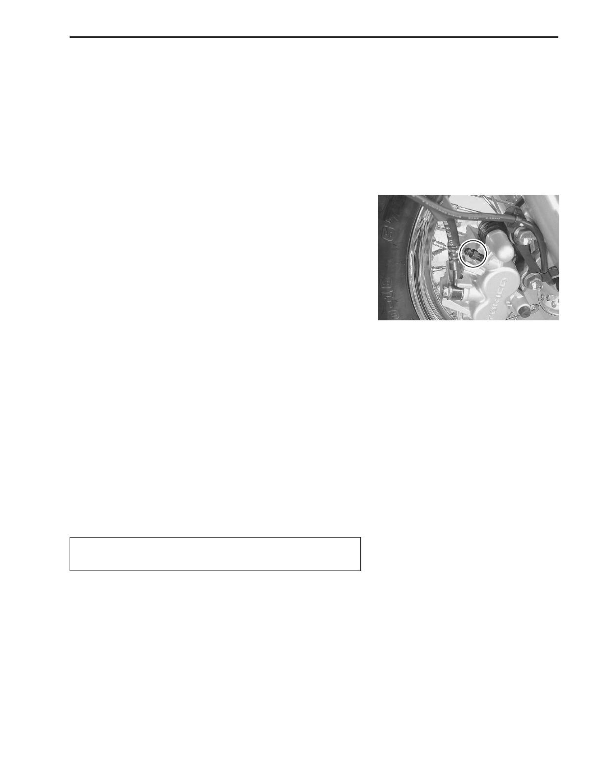
FRONT BRAKE
Fill the master cylinder reservoir to the top of the inspection
window. Replace the reservoir cap to prevent dirt from enter-
ing.
Attach a hose to the air bleeder valve and insert the free end of
the hose into a receptacle.
Squeeze and release the brake lever several times in rapid
succession and squeeze the lever fully without releasing it.
Loosen the air bleeder valve by turning it a quarter of a turn so
that the brake fluid runs into the receptacle, this will remove the
tension of the brake lever causing it to touch the handlebar
grip. Then, close the air bleeder valve, pump and squeeze the
lever, and open the valve. Repeat this process until fluid flow-
ing into the receptacle no longer contains air bubbles.
NOTE:
While bleeding the brake system, replenish the brake fluid in the
reservoir as necessary. Make sure that there is always some fluid
visible in the reservoir.
Close the air bleeder valve and disconnect the hose. Fill the
reservoir with brake fluid to the top of the inspection window.
'Air bleeder valve: 8 N.m (0.8 kgf.m, 6.0 Ib-ft)
%
Handle brake fluid with care: the fluid reacts chemically
with paint, plastics, rubber materials, etc.
2-18 PERIODIC MAINTENANCE
TIRE PRESSURE
If the tire pressure is too high or too low, steering will be ad-
versely affected and tire wear will increase. Therefore, maintain
the correct tire pressure for good roadability and a longer tire life.
Cold inflation tire pressure is as follows.
"Cold inflation tire pressure
Solo riding: Front: 200 kPa (2.00 kgf/cm2, 29 psi)
Rear: 250 kPa (2.50 kgf/cm2, 36 psi)
Dual riding: Front: 200 kPa (2.00 kgf/cm2, 29 psi)
Rear: 250 kPa (2.50 kgf/cm2, 36 psi)
%
The standard tire fitted on this motorcycle is a 130/90-15
67H for the front and a 170/80-15 H/C 77H for the rear.
The use of tires other than those specified may cause
instability. It is highly recommended to use the specified
tires.
"TIRE TYPE
IRC
FRONT: GS-23F
REAR : GS-23R
TIRES
TIRE TREAD CONDITION
Operating the motorcycle with excessively worn tires will decrease
riding stability and consequently invite a dangerous situation. It is
highly recommended to replace a tire when the remaining depth
of tire tread reaches the following specification.
(09900-20805: Tire depth gauge
"Tire tread depth:
Service Limit: FRONT 1.6 mm (0.06 in)
REAR 2.0 mm (0.08 in)
PERIODIC MAINTENANCE 2-19
STEERING
The steering should be adjusted properly for smooth turning of
the handlebars and safe operation. Overtight steering prevents
smooth turning of the handlebars and too loose steering will cause
poor stability. Check that there is no play in the front fork. Support
the motorcycle so that the front wheel is off the ground. With the
wheel facing straight ahead, grasp the lower fork tubes near the
axle and pull forward. If play is found, readjust the steering. (!
7-35)
FRONT FORK
Inspect the front forks for oil leakage, scoring or scratches on the
outer surface of the inner tubes. Replace any defective parts, if
necessary. (!7-18)
REAR SUSPENSION
Inspect the rear shock absorbers for oil leakage and check that
there is no play in the swingarm. Replace any defective parts if
necessary. (!7-46)
EXHAUST PIPE BOLT AND NUT
Tighten the exhaust pipe bolts and muffler bolts and nuts.
2-20 PERIODIC MAINTENANCE
CHASSIS BOLTS AND NUTS
Check that all chassis bolts and nuts are tightened to their specified torque. The locations of the following nuts
and bolts on the motorcycle.
Item N.m kgf.m Ib-ft
1 Steering stem head nut 90 9.0 65.0
2 Steering stem lock nut 80 8.0 58.0
3 Front fork lower clamp bolt 33 3.3 24.0
4 Front fork cap bolt 35 3.5 25.5
5 Front axle 65 6.5 47.0
6 Front axle pinch bolt 33 3.3 24.0
7 Handlebar set bolt 70 7.0 50.5
8 Handlebar clamp bolt 23 2.3 16.5
9 Front brake master cylinder mounting bolt 10 1.0 7.0
0 Front brake caliper mounting bolt 39 3.9 28.0
A Brake hose union bolt 23 2.3 16.5
B Caliper air bleeder valve 8 0.8 6.0
C Brake disc bolt 23 2.3 16.5
D Swingarm pivot nut 100 10.0 72.5
E Torque link bolt and nut (Front) 35 3.5 25.5
F Torque link bolt and nut (Rear) 25 2.5 18.0
G Rear shock absorber mounting bolt/nut 50 5.0 36.0
(Upper & Lower)
H Rear cushion lever/rod mounting nut 78 7.8 56.5
I Rear axle nut 65 6.5 47.0
J Brake cam lever nut 10 1.0 7.0
  • Page 1 1
  • Page 2 2
  • Page 3 3
  • Page 4 4
  • Page 5 5
  • Page 6 6
  • Page 7 7
  • Page 8 8
  • Page 9 9
  • Page 10 10
  • Page 11 11
  • Page 12 12
  • Page 13 13
  • Page 14 14
  • Page 15 15
  • Page 16 16
  • Page 17 17
  • Page 18 18
  • Page 19 19
  • Page 20 20
  • Page 21 21
  • Page 22 22
  • Page 23 23

Suzuki VL 800 Owner's manual

Category
Motorcycles
Type
Owner's manual

The Suzuki VL 800 is a powerful and versatile motorcycle that offers a smooth and comfortable ride. With its 805cc, 4-stroke, V-twin engine, it delivers ample power for cruising and long-distance travel. The VL 800 also features a low seat height, making it easy to mount and maneuver, especially for shorter riders. Additionally, its fuel-efficient performance and user-friendly controls make it a great choice for both experienced and novice riders.

Ask a question and I''ll find the answer in the document

Finding information in a document is now easier with AI