Page is loading ...

INVERT EASE INVERSION TABLE
ITEM NO: 75303
OWNER’S MANUAL
IMPORTANT: Read all instructions carefully before using this product. Retain this
owner’s manual for future reference.
The specifications of this product may vary from this photo and are subject to change without
prior notice. 2018, Sept.

1
TABLE OF CONTENTS
WARRANTY ------------------------------------------------------------------------------- 2
IMPORTANT SAFETY INSTRUCTIONS ------------------------------------------- 3
EXPLODED VIEW ----------------------------------------------------------------------- 5
PARTS LIST ------------------------------------------------------------------------------- 7
HARDWARE LIST ----------------------------------------------------------------------- 9
TOOLS -------------------------------------------------------------------------------------- 9
ASSEMBLY INSTRUCTIONS --------------------------------------------------------- 10
HOW TO USE ----------------------------------------------------------------------------- 16
QUICK RELEASE ANKLE LOCK ---------------------------------------------------- 20
OPERATION ------------------------------------------------------------------------------ 21
STORAGE --------------------------------------------------------------------------------- 22
WARM UP AND COOL DOWN ROUTINE ---------------------------------------- 23

2
ONE YEAR LIMITED WARRANTY
LifeGear Inc. warrants to the original purchaser that this product is free from defects in
material and workmanship when used for the purpose intended, under the conditions that it
has been installed and operated in accordance with LifeGear's Owner's Manual. LifeGear's
obligation under this warranty is limited to replacing or repairing free of charge, any parts
which may prove to be defective under normal home use. This warranty does not include
any damage caused by improper operation, misuse or commercial application.
From the date of purchase, the frame is warranted to be free from defects for 1 (one) year.
This warranty is offered only to the original owner and is not transferable. Proof of
purchase is required.
When ordering replacement parts please have the following information ready:
1. Owner's Manual
2. Model Number
3. Description of Parts
4. Part Number
5. Date of Purchase

3
IMPORTANT SAFETY INSTRUCTIONS
This inversion table was designed and built for optimum safety. However, certain
precautions apply whenever you operate the exercise equipment. Be sure to read the
entire manual before assembling and operating this equipment. When using an inversion
table, basic precautions should always be followed, including the following:
WARNING: To reduce the risk of personal injury, read and understand all
instructions before using the inversion table.
1. Consult your physician or other health care professionals before using the inversion
table.
2. Use the inversion table only for its intended use as described in this manual. Do not
use attachments not recommended by the manufacturer.
3. Never operate the inversion table if it is damaged, if it is not working properly, if it has
been dropped or otherwise damaged. Please contact your local service center for
examination and repair.
4. Do not use or store the inversion table outdoors.
5. Do not exceed the maximum rated weight (load) or maximum rated height of the user.
6. For Home Use Only.
7. Always wear appropriate clothing while using the inversion table i.e. no loose fitting
clothing that could be caught in moving parts.
8. If any time you feel faint, light-headed or dizzy while operating the equipment, stop use
immediately and slowly return to the upright position. You should also stop inverting if
you are experiencing pain or pressure.
9. Only one person should use the equipment at a time.
10. Make sure your equipment is correctly assembled before you use it. Be sure all
screws, nuts, and bolts are tightened prior to use.
11. After you finish inverting: come up slowly, should dizziness occur after a session it
means you came up too fast. Reduce the rate at which you return to the upright
position. Wait a reasonable period of time between eating and using the inversion
table. If you feel nauseated, come up as soon as you feel queasy.
12. Always use this equipment on a clear and level surface. Do not use near water.
13. The inversion table is not designed for use by children or anyone shorter than the
minimum height indicated on the adjustable boom.
14. Close supervision is necessary when this inversion table is used by, on, or near invalids,
or disabled persons.
15. Never drop or insert any object into any opening.
16. WARNING: Keep hand on the brake while inverting.
17. WARNING: Risk of injury - Keep children away from machine while in use.
18. WARNING : Risk of personal injury - Do not grab the Lock Handle to return
to upright. Instead use the handlebar.

4
19. WARNING: Risk of personal injury - Keep body parts, hair, loose clothing
and jewelry clear of all moving parts.
NOTE: Maximum user weight for this product is 160 kgs.
Maximum Rated Height for this product is 200 cm.
WARNING: Before using this equipment you should consult with your
personal physician to see if inversion equipment is appropriate for you. Do not use
this equipment without your physician's approval. Please do not nor let anyone else
use this equipment if any of the following apply:
Extreme obesity
Glaucoma, retinal detachment or conjunctivitis
Pregnancy
Spinal injury, Cerebral Sclerosis, or acutely swollen joints
Middle ear infection
High blood pressure, Hypertension, Recent stroke or Transient ischemic attack
(Mini Strokes)
Heart or circulatory disorders for which you are being treated
Hiatus hernia or Ventral hernia
Bone weaknesses including Osteoporosis, Unhealed fractures, Modularly pins
(Surgically implanted bone pins), or Surgically implanted orthopedic supports
Use of anti-coagulants including Aspirin in high doses
SAVE THESE INSTRUCTIONS FOR FUTURE
REFERENCE

5
EXPLODED VIEW

6
EXPLODED VIEW

7
PARTS LIST
No.
Description Qty
No.
Description Qty
001 Front Frame 1 030 Knob 1
002 Cup Holder 1 031 Rubber Heel Holder 2
003 Rear Frame 1 032
Cross Recessed Oval Head Bolt
M6x30
1
004 Cup Holder Rotation Cap 1 033 Lock Mechanism 1
005 Front Heel Holder 2 034 Lock Handle Plastic Bar 1
006 Gear Plate 1 035 Foam Bed 1
007 Heel Holder Bracket 2 036 Handlebar Foam Grip 2
008 Adjustable Boom 1 037 Metal Sleeve 1
009 Rear Rod 1 038 Bolt M8x60 4
010 Bed Frame 1 039 Front Plastic Cover 1
011 Front Rod 1 040L
Left Plastic Cover 1
012 Right Pivot Arm 1 040R
Right Plastic Cover 1
013 Washer Ø8.5xØ20xt1.5 18
041
Square End Cap □38
2
014 Curve Washer Ø8.5xØ16xt2.0 2 042 Lock Pin 1
015 Lock Nut M8 (Galvanize) 6 043 Bolt M8x12 2
016 Lock Nut M6 1 044 Height Scale 1
017 Blocking Bush Ø28.5xØ23x14 2 045 Washer Ø8.5xØ24x2mm 2
018 Spring Knob 1 046 Bolt M8x20 6
019 Left Pivot Arm 1 047 Brake Bracket 1
020 Rubber Pad M6x10xØ35x15 1 048 Upper Plastic Cover 1
021 Right Brake Pad I 1 049 Rear Foot Cap 2
022L
Left Adjustable Boom Plate 1 050 Bolt M6x25 1
022R
Right Adjustable Boom Plate 1 051 Bolt M6x15 4
023 In-Step Frame 2 052 Lower Plastic Cover 1
024 In-Step Foot Pad 2 053 Front Foot Cap 2
025 Round End Cap 2 054
Pivot Arm Rotation Cap I
Ø60xØ19.5x18
2
026 Rod Cap 2 055
Pivot Arm Rotation Cap II
Ø60xØ19.5x21
1
027 056 Adjustable Handle 1
028 Fixed Plate 1 057 Handle Cap 1
029 Handlebar 2 058 Handle Spring 1

8
PARTS LIST
No.
Description Qty
No.
Description Qty
059 Button 1 074 Rotor Cover 1
060 Handle Tip 1 075 Left Brake Pad II 1
061 Blocking Bush Ø28.5xØ22.5x10 2 076 Pin 1
062 Screw ST3.5x10 19
077 Washer Ø4.3xØ9xt0.3 4
063
Spring Washer
Ø8.1xØ12.3x2.1mm
4 078 Lock Nut M8 6
064 Carriage Bolt M8x60 2 079 Spring 1
065 Bolt M6x30 1 080 Brake Pad 2
066 Spacer Ø22xØ16.8 2 081 Bolt M4x20 1
067 Screw ST4.2x12 8 082 Cap 4
068 Screw ST4.8x20 1 083
Rectangle End Cap □50x25
4
069 Shaft Nut Ø8 1 084 Upper Bed Frame End Cap 1
070 Bolt M5x10 2 085 Lower Bed Frame Bushing 2
071 Bolt M8x50 4 086 Bolt M8x40 4
072 Round Cap 1 087 Tube Clamp 1
073 Bolt M4x16 1

9
HARDWARE LIST
TOOLS
Multi Hex Tool with Phillips Screwdriver
1 PC
Allen Wrench #5
1 PC
Allen Wrench #6
1 PC
(13) Washer
Ø8.5xØ20xt1.5
10 PCS
(15) Lock Nut M8
(Galvanize)
4 PCS
(38) Bolt M8x60
2 PCS
(43) Bolt M8x12
2 PCS
(46) Bolt M8x20
4 PCS
(51) Bolt M6x15
4 PCS
(81) Bolt M4x20
1 PC
(82) Cap
4 PCS
(14) Curve Washer
Ø8.5xØ16xt2.0
2 PCS
(76) Pin
1 PC
(63) Spring Washer
Ø8.1xØ12.3x2.1mm
2 PCS

10
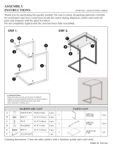
ASSEMBLY INSTRUCTIONS
Step 1
Lay the base on its side as shown. Attach the Front Foot Caps (53) to the Front Frame (1)
each with one Ø8.5xØ20xt1.5 Washer (13) and one M6x15 Bolt (51).
Attach the Rear Foot Caps (49) to the Rear Frame (3) each with one Ø8.5xØ20xt1.5 Washer
(13) and one M6x15 Bolt (51).
Tighten bolts with the Multi Hex Tool with Phillips Screwdriver provided.
Front Foot Cap is marked with F.
Rear Foot Cap is marked with R.
NOTE: The weight of the product is more than 20 kg and it should be assembled and
moved by two or more people.
Hardware:
(51) Bolt M6x15
4 PCS
(13) Washer
Ø8.5xØ20xt1.5
4 PCS

11
Step 2
Stand up the base and open fully. Make sure all Foot Caps are level. Insert the Pin (76)
into Frames.
Install two Caps (82) onto two M8 Lock Nuts (15).
Hardware:
Correct Incorrect
(76) Pin
1 PC
(82) Cap
2 PCS

12
Step 3
Attach the Bed Frame (10) onto the Right Pivot Arm (12) and Left Pivot Arm (19) by using
two M8 Lock Nuts (15), two M8x12 Bolts (43), two M8x20 Bolts (46) and two Ø8.5xØ20xt1.5
Washers (13). Tighten M8x12 Bolts (43) with #5 Allen Wrench provided. Tighten M8x20
Bolts (46) and M8 Lock Nuts (15) with #6 Allen Wrench and Multi Hex Tool with Phillips
Screwdriver provided.
Install the Knob (30) onto the Bed Frame (10)
Hardware:
(13) Washer
Ø8.5xØ20xt1.5
2 PCS
(15) Lock Nut M8
(Galvanize)
2 PCS
(43) Bolt M8x12
2 PCS
(46) Bolt M8x20
2 PCS

1
3
Step 4
Attach both Handlebars (29) onto Rear Frame (3) with four Ø8.5xØ20xt1.5 Washers (13),
two Ø8.5xØ16xt2.0 Curve Washers (14), two M8 Lock Nuts (15), two M8x60 Bolts (38), two
M8x20 Bolts (46), and two Ø8.1xØ12.3x2.1mm Spring Washers (63). Tighten M8x20 Bolts
(46) with #6 Allen Wrench provided. Tighten M8x60 Bolts (38) and M8 Lock Nuts (15) with
#6 Allen Wrench and Multi Hex Tool with Phillips Screwdriver provided, attach the Caps (82)
to the M8 Lock Nuts (15).
Install the Cup Holder (2) to the Cup Holder Rotation Cap (4).
Install the Lock Handle P Bar (34) onto the Lock Mechanism (33) and secure with one
M4x20 Bolt (81). Tighten M4x20 Bolts (81) with the Multi Hex Tool with Phillips Screwdriver
provided.
Hardware:
(13) Washer
Ø8.5xØ20xt1.5
4 PCS
(15) Lock Nut M8
(Galvanize)
2 PCS
(14) Curve Washer
Ø8.5xØ16xt2.0
2 PCS
(38) Bolt M8x60
2 PCS
(46) Bolt M8x20
2 PCS
(81) Bolt M4x20
1 PC
(82) Cap
2 PCS
(63) Spring Washer
Ø8.1xØ12.3x2.1mm
2 PCS

14
Step 5
Slide two Heel Holder Brackets (7) and Rubber Heel Holders (31) onto both ends of the Rear
Rod (9) until the lock teeth are wedged into the slots in the Rear Rod (9), as shown in
detailed drawing below.
Slide Front Heel Holder (5) onto Front Rod (11).
Turn Rod Cap (26) clockwise onto the Front Rod (11).
NOTE: Make sure the lock teeth are wedged into the slots
in the Rear Rod (9) to lock the Heel Holder Brackets (7)
and Rubber Heel Holders (31) in place before use.

15
Step 6
Pull the Spring Knob (18) and slide the Adjustable Boom (8) in. Slide the Adjustable Boom
(8) up to the desired height. Release the Spring Knob (18) and make sure it “pops” into the
hole.
Step 7
Install the Knob (30) onto the Bed Frame (10) and tighten it for additional safety.

16
1
Make sure the Lock Handle
Plastic Bar is at LOCK position.
2
Pull the Adjustable Handle until ankle pads lock
on the feet securely.
Wearing shoes will help ankles stay more secure.
HOW TO USE
Set the Adjustable Boom to your height
Turn the Knob counter-clockwise to loosen the Adjustable Boom. Pull the Spring Knob as
you adjust the Adjustable Boom to desired height. Turn the Knob clockwise to make sure
the Adjustable Boom is tight.
Mounting the table
Adjustable
Boom
Spring Knob
Knob

17
Get to inversion
1. Start by lying fully back on the bed with your hands at your side, or resting on your
thighs.
2. Keeping your hands close to your body, begin to raise your left arm slowly allowing the
table to rotate backward. Stop, or lower your arm to control the downward rotation of
the table keep your right hand on the brake.
3. Raise your arm until you reach the position you are comfortable with at this point
engage the brake to lock the table bed at this angle. You may now relax your right
arm.
4. Release the brake and return to the upright position by slowly moving your hands back
and grip both handlebars.
Push the Lock Handle Plastic
Bar to UNLOCK position.
With both hands on handles,
slowly lie down.

18
Get to vertical inversion
Push against the inversion bar
with left arm.
1
Pull the Lock Handle Plastic
Bar to LOCK position.
2
When you’re at desired angle, pull
the Lock Handle Plastic Bar forward
to LOCK position to lock the bed.

19
1
Make sure the Lock Handle
Plastic Bar is at LOCK position.
1. Pull the Adjustable Handle.
2. Press the Button.
3. Push the Adjustable Handle forward.
2
Dismounting the table
Calibrating the Brake
The brake might become slightly
loose after long period of use. To
tighten, insert the Phillips
Screwdriver into the hole as
indicated on the diagram, turn the
calibrating screw inside clockwise
no more than 1/4 turn.
/