
MEIDER2100
Model No. 831.159010
Serial No.
Write the serial number in the
space above for reference.
Serial Number Decal (under seat)
_" X F-. R C I S E.
EQUIPMENT
HELPLINE!
!-800-736-6879
SEARS, ROEBUCK AND CO.
HOFFMAN ESTATES, IL 60179
USER'S MANUAL
www.weiderfit ness.com
new products, prizes,
fitness tips, and much more!

TABLE OF CONTENTS
IMPORTANT PRECAUTIONS ............................................................. 3
BEFORE YOU BEGIN ................................................................... 4
ASSEMBLY ........................................................................... 5
ADJUSTMENTS ...................................................................... 14
WEIGHT RESISTANCE CHART ........................................................... 16
CABLE DIAGRAM ..................................................................... 17
EXERCISE GUIDELINES ................................................................ 18
ORDERING REPLACEMENT PARTS ................................................ Back Cover
LIMITED WARRANTY ........................................................... BackCover
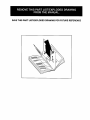
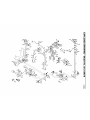
Note:A PART IDENTIFICATION CHART and a PART LIST/EXPLODED DRAWING are attached in the center of
this manual. Remove the PART IDENTIFICATION CHART and the PART LIST/EXPLODED DRAWING before
beginningassembly.
WELDER is a registeredtrademark of ICON Health & Fitness, Inc.
2

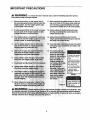
IMPORTANT PRECAUTIONS
WARNING: To reduce the rlsk of serious injury, reed the following Important precau-
tions before using the weight system.
1, Read all Instructions in this manual and In
the accompanying literature before using the
weight system. Use the weight system only
as described in this manual.
11. Make sure that the cables remain on the pul-
leys at all times. If the cables bind while you
are exercising, stop Immediately and make
sure that the cables are on all of the pulleys.
2. It Is the responsibility of the owner to ensure 12. Always stand on thefoot plate when per-
that an users of the weight system are ade- formlng an exercise that could cause the
quately Informed of all precautions, weight system to tip.
3. The weight system Is Intended forhome use 13. Always disconnect the lat bar from the
Ing down.
7. Keep hands and feet eway;frommovlngparts:
9,
our toll-free HELPLINE
Uon shown.
• Misuseofthisproduct
mayresultinserious
injury.
•Readuser'smanual
andfollowall warnings
andooeratinginstruc
tionsenortouse
•Donotallowchilaren
onorarounomacn_ne
•Replacelabelif
damaged,illegible,or
removeo.
Decal I
10. Never release the press arm, butterftyfarms,
leg lever, at bar, ()r handle whllewelgh;ts_are
raised, the weights will fall with great force.
Decal 2
3

BEFORE YOU BEGIN
Thank you for selectingthe versatile WELDER®2100
weight system.The WELDER" 2100 offersa selection
of weightstationsdesigned todevelop every major
musclegroup ofthe body.Whether yourgoal isto tone
your body,builddramatic muscle size and strength,or
improveyourcardiovascularsystem,the WELDER®
2100 will helpyou to achieve the resultsyou want.
For your benefit, read this manual carefully before
using the weight system, ifyou have additional
questions,please call ourtoll-free HELPLINE at
1-800-736-6879, Monday throughSaturday,7 a.m.
until7 p.m. Central Time (excludingholidays).To help
usassistyou, please note the productmodelnumber
and serial number beforecalling.The model numberis
831.159010. The serial numbercan befound on a
decal attached to the weightsystem (see the front
coverof this manual).
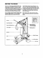
Before readingfurther,please review the drawing
belowand familiarizeyourselfwith the parts that are
labeled.
LSt Bar
High PulleyStation
PressArm/Butterfly
Front Upright
ASSEMBLED
DIMENSIONS:
Height: 74 in.
Width: 42 in.
Length: 60 in.
Warning Decal 2
(One on each side
of the front upright.)
Decal 1
Backrest
Seat
Weight Carriage
Leg Lever
Low Pulley Station
Foot Plate
4

ASSEMBLY
• As you assemble theweight system,make sure
all parts are orientedas shownin the drawings.
Before beginning assembly, carefully rend the
following Information and Instructions:
• Assemblyrequirestwo people.
• Place all parts in a cleared area and remove the
packing materials. Do not disposeof the packing
materials untilassembly iscompleted.
• "13ghtenall partsas you assemble them, unless
instructedto do otherwise.
• For help identifyingsmall parts, use the PART
The following tools (not Included) are required
for assembly:
• two adjustable wrenches
• one rubber mallet
• one standard screwdriver
• one Phillips screwdriver
• lubricant, such as grease or petroleum jelly,
and soapy water.
Assemblywillbe moreconvenientifyou have a
socketset, a set of open-endor closed-end
wrenches, or a set of ratchetwrenches.
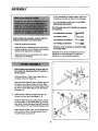
1.
2.
Before beginning assembly, be sure that you
have rend and understand the Information In
the box above.
Presstwo 50mm x 75mm Inner Caps (29) into
the sides ofthe Foot Plate (74).
Orientthe Rear Base (3) with the indents around
the holeson the bottom.Attach the Front Base
(1) and the Rear Base tothe Center Base (2) with
two M10 x 70mm Bolts(58) and two M10 Nylon
Locknuts(71).
Insertsix M10 x 65mm Carriage Bolts(57) up
throughthe Frontand Rear Bases (1, 3).
Press the three Base Caps (28) onto the ends of
the Front Base (1), the Center Base (2), and the
Rear Base. Secure the Base Caps withthree M4
x 20mm Screws(77) and three M5 Washers (75).
Attachthe Foot Plate (74) to the Center Base (2)
withtwo M10 x 65mm Carriage Bolts(57) and
two M10 Nylon Locknuts(71).
2
28
75
3
71
2
58 Indents
1
58
29
74
77
1
2
71
_75
77
-71
57 57
5

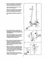
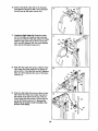
3. Attach the Rear Upright (7) to the Rear Base (3)
with the two indicatedM10 x 65mm Carriage
Bolts(57) and two M10 Nylon Locknuts(71).
Press a 38mm Square InnerCap (41) intothe
tube on the Front Upright (6).
Attachthe Front Upright (6) to the FrontBase (1)
with thetwo indicatedM10 x 65mm Carriage
Bolts(57) and two M10 Nylon Locknuts(71).
Do not tighten the MIO Nylon Locknuts (71)
yet.
4.
Press a 50mm Square Inner Cap (22) intothe
Seat Upright (73). Attachthe Bumper (25) to the
Seat Uprightwith an M4 x 20mm Screw (77) and
an M5 Washer (75).
Attachthe Seat Upright(73) to the Front Base (1)
with the two indicatedM10 x 65mm Carriage
Bolts(57) and two M10 Nylon Locknuts(71). Do
not tighten the Nylon Locknute yet.
5.
Make sure there is a Carriage Bushing(32) inside
the top of the Carriage Stop (31). Slide the
Carriage Stop onto the Rear Upright(7) and
attach itat the indicatedhole (see the insetdraw-
ing) withan M8 x 70mm Bolt(72) and an M8
Nylon Locknut (70).
Make sure there are two Carriage Bushing(32)
inside thetop and bottomof the Weight Carriage
(14). Presstwo 25mm Round Inner Caps (33)
intothe ends of the tube on the Weight Carriage.
Insertan M10 x 20mm Bolt(67) intothe bracket
on the Weight Carriage.
Slide the Weight Carriage (14) ontothe Rear
Upright (7). Press a 50mm Square Inner Cap (22)
ontothe top of the Rear Upright.
4
77
5
6
71
1
57
22
75
57

6. Pressa 50mm Square Inner Cap (22) intothe
end of the Top Frame (8).
Attachthe Top Frame (8) to the Front Upright(6)
withtwo M10 x 70mm Bolts(58), the 90mm
Space SupportPlate (21), and two M10 Nylon
Locknuts(71).
Attach the Top Frame (8) tothe Rear Upright(7)
with two M1Ox 70mm Bolts(58), the 70mm
Space Support Plate (56), and an M10 Nylon
Locknut(71).
0o not tighten the M10 Nylon Looknuts (71)
yet.
7. Attachthe Seat Frame (5) to the Front Upright(6)
withtwo M10 x 70ram Bolts(58), two M10
Washers (26), and two M10 Nylon Locknuts(71).
Attach the Seat Frame (5) to the Seat Upright
(73) with two M10 x 70ram Bolts (58), two M10
Washers (26), and two M10 Nylon Locknuts(71).
Tighten the M10 Nylon Locknuts (71) used In
steps 2-7.
8.
Press a 50mm Square Inner Cap (22) intothe
ButterflyFrame (9).
Lubricatethe M10 x 75mm Bolt(60) with grease.
Attach the ButterflyFrame (9) to the Top Frame
(8) withthe Boltand an M10 Nylon Locknut(71).
Do not overtlghten the Locknut; the Butterlly
Frame must be able to pivot easily.
6
58
•0 " i
22 ..-'_
6O
7

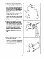
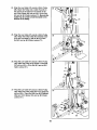
9. 9
Press a 40mm x 50mm Inner Cap (23) intothe
indicatedend of the RightButterflyArm (11). Wet
the bottomend of theArm with soapy water. Slide
a Large Foam Pad (19) ontothe Arm.
Attach a Pivot Bracket (48) to the Right Butterfly
Arm (11) with an M10 x 50mm Bolt(62) and an
M10 Nylon Locknut(71). Do not overtlghten the
Looknut; the Pivot Bracket must be able to
pivot easily.
Slide a Foam Grip (76) ontothe Right Handle
(13). Attachthe Handle to the Right ButterflyArm
(11) withtwo M8 x 15ram Bolts(64).
Slide the Large Foam Pad (19) down sothat the
bottomof the Foam Pad iseven with the bottomof
the Arm.
Repeat this step with the Left Butterfly Arm (10).
10. Lubricatean M10 x 82mm Bolt(50) and both
sides of two PlasticWashers (55) with grease.
Attach the Right ButterflyArm (11) tothe Butterfly
Frame (9) withthe Bolt, the two PlasticWashers,
two ButterflyCaps (54), and an M10 Nylon
Locknut(71). Do not overtlghten the Locknut;
the Butterfly Arm must be able to pivot easily,
Be sure the indented sides of the Plastic
Washers fit over the welded bushing In the
Butterfly Arm.
Repeat this step with the Left Butterfly Arm
(10).
11. Press two 40mm x 50mm Inner Caps (23) into
the ends of the Leg Lever (4).
Lubricatean M10 x 65mm Bolt (59) with grease.
Attach the Leg Lever (4) to the Seat Upright(73)
with the Boltand an M1ONylon Locknut(71). Do
not overt_ghten the Locknut; the Leg Lever
must be able to pivot easily.
11
10
11
11
Welded Lubricate
Bushir x'_50
'l
55_ " ""-
9 "" i
Lubricate
71
73
23
4 _ Lubricate
23--
8

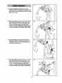
12. Locate the Butterfly Cable (46). Attach the
ButterflyCable to the indicatedPivotBracket (48)
with an M8 x 27mm Shoulder Bolt(63) and an M8
Nylon Locknut (70).
13. Wrap the ButterflyCable (46) arounda "V"-Pulley
(39). Attach the Pulley and a Long Cable Trap
(40) tothe bracket on the Front Upright(6) with
an M10 x 55mm Bolt (69) and an M10 Nylon
Locknut(71). Be sure the Cable Trap Is turned
to hold the Cable In the Groove of the Pulley.
14, Wrap the ButterflyCable (46) arounda 90mm
Pulley(38). Attach the Pulleytothe Double"U"-
Bracket (37) with an M10 x 47mm Bolt (61) and
an M10 Nylon Locknut(71).
15. Wrap the ButterflyCable (46) arounda "V"-Pulley
(39). Attach the Pulleyand a Long Cable Trap
(40) to the bracket on the Front Upright(6) with
an M10 x 55mm Bolt(69) and an M10 Nylon
Locknut(71). Be sure the Cable Trap Is turned
to hold the Cable In the Groove of the Pulley.
13
,,6
/71
39
4_/_/69
46
15
46
9

16. Attach the ButterflyCable (46) to the indicated
Pivot Bracket (48) with an M8 x 27mm Shoulder
Bolt (63) and an M8 Nylon Locknut (70).
17. Locate the High Cable (45). Routethe eyelet
end of the Cable up throughthe Top Frame (8)
and arounda 90mm Pulley(38). Attach the Pulley
inside the Top Frame with an M1Ox 7Omm Bolt
(58), two M10 Washers (26), two 13mm Spacers
(34), and an M1O Nylon Locknut(71).
18. Wrap the High Cable (45) around a 90mm Pulley
(38). Attachthe Pulley insidethe Top Frame (8)
withan M10 x 70mm Bolt (58), two M1OWashers
(26), two 13mm Spacers (34), and an M1ONylon
Locknut (71).
19. Wrap the High Cable (45) arounda 90mm Pulley
(38). Attach the Pulleyand a Cable Trap (44) to
the second set of holesfrom the top ofthe two
PulleyPlates (36) with an M10 x 47mm Bolt(61)
and an M10 Nylon Locknut(71). Be sure the
Cable Trap Is turned to hold the Cable In the
Groove of the Pulley.
16
17
71 34
18
19
7O
8
6
.,61
36 _
10

20. Wrap the High Cable (45) around a 9Omm Pulley
(38). Attachthe Pulley insidethe Top Frame (8)
with an M10 x 70mm Bolt(58), two M1OWashers
(26), two 13mm Spacers (34), and an M10 Nylon
Locknut(71).
21. Attach the eyelet end of the High Cable (45) to
the M10 x 20mm Bolt(67) in the bracket on the
Weight Carriage (14) with an M1O Nylon Locknut
(71).
22. Locatethe Low Cable (47). Routethe Cable
throughthe cage and rest it inthe bracketson the
Center Base (2).
Attach a 90mm Pulley (38) insidethe indicated
bracket on the Center Base (2) with an M10 x
47mm Bolt (61) and an M10 Nylon Locknut(71).
23. Attach a 90mm Pulley(38) insidethe indicated
bracket on the Center Base (2) with an M10 x
47mm Bolt(61) and an M10 Nylon Locknut(71).
2O
21
38
145
34
26
61
Cage
23
38
61 e,;1
11

24. Wrap the Low Cable (47) arounda 90mm Pulley
(38). Attach the Pulleyand a Cable Trap (44) to
the second set of holesfrom the bottomof the
two PulleyPlates (36) with an M10 x 47mm Bolt
(61) and an M10 Nylon Locknut(71). Be sure the
Cable Trap Is turned to hold the Cable In the
Groove of the Pulley.
25. Wrap the Low Cable (47) arounda 90mm Pulley
(38). Attach the Pulleyinside the indicatedbrack-
et on the Front Base (1) with an M10 x 47mm
Bolt(61) and an M10 Nylon Locknut(71).
26. Wrap the Low Cable (47) around a 90mm Pulley
(38). Attachthe Pulley tothe Double=U"-Brasket
(37) with an M1Ox 47mm Bolt(61) and an M10
Nylon Locknut(71).
27. Wrap the Low Cable (47) arounda 90mm Pulley
(38). Attach the Pulley insidethe Front Upright(6)
with an M10 x 70mm Bolt(58), two M10 Washers
(26), two 13mm Spacer (34), and an M10 Nylon
Locknut (71).
24
25
I
61
26
38-_ 61
47_
27
34
6
58
12

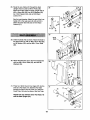
28. Route the Low Cable (47) throughthe Seat
Upright (73) and under a 90mm Pulley (38).
Attach the Pulley insidethe Seat Uprightwith an
M10 x 65mm Bolt (59), two M10 Washers (26),
two 13mm Spacer (34), and an M10 Nylon
Locknut(71).
See the inset drawing.Attach the end of the Low
Cable (47) to the Leg Lever (4) with an M10 x
28mm Shoulder Bolt (78) and an M10 Nylon
Locknut (71).
29. Orient the Seat (16) as shown. Attachthe Seat to
the Seat Frame (5) with an M6 x 65mm Bolt(65),
an M6 Washer (35), and two M6 x 15mm Bolts
(66).
30. Attachthe Backrest(15) to the FrontUpright (6)
withtwo M6 x 65mm Bolts(65), and two M6
Washers (35).
31. Press two 19mm Round Inner Caps (27) intothe
ends of a Pad Tube (17). Slidethe Pad Tube
throughthe hole in the Leg Lever (4). Slidetwo
Foam Pads (18) ontothe ends of the PadTube.
Repeat this step with the other Pad Tube (17)
and the Seat Upright (73).
28
T_4 47
78
29
30
31
47
59
Wide 1_
End _
5
66
II 5 Ill
18
27
18
13

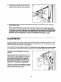
32. Insertthe two LockingPins (53) intothe Butterfly
Frame (9). Attach the tether on the Pins to the
Butterfly Frame with the M4 x 10mm Screw (68).
32
9
53
33. Make sure that all parts have been properlytightened.The use ofall remainingparts willbe explained in
ADJUSTMENTS, below.
Before usingtheweight system,pulleach cable a few timesto make surethat the cablesmove smoothly
over the pulleys.Ifone ofthe cables does not movesmoothly,find and correctthe problem.IMPORTANT: If
the cables are not properly routed, they may be damaged when heavy weight Is used. See the CABLE
DIAGRAM on page 17 of this manual for proper cable routing. If there Is any alack In the cables, you
wM need to remove It by Ughtenlng the cables; see TIGHTENING THE CABLES on page 15.
ADJUSTMENTS
This sectionexplains how to adjustthe weight system.See the EXERCISE GUIDELINES on page 18 for impor-
tant informationabout how to get the mostbenefitfrom yourexercise program.Also, refer to the accompanying
exercise guide to see the correctform for each exercise.
Make sure all partsare properly tightenedeach timethe weightsystem isused. Replaceanywornpartsimmediate-
ly.The weightsystemcan be cleanedwitha damp clothand a mild,non-abrasivedetergent.Do not use solvents.
A'n'ACHING THE ACCESSORIES TO A PULLEY
STATION
Attach the Lat Bar (42) to the High Cable (45) with a
Cable Clip (52). For some exercises,the Chain (not
shown) should be attached between the Lat Bar and
the High Cable with two Cable Clips. Adjust the
length of the Chain between the Lat Bar and the
Short Cable so the Lat Bar Is In the correct start-
ing position for the exercise to be performed.
The Handle (not shown)can be attached in the same
manner. The accessoriescan be attached to the Low
Cable (not shown) in the same manner.
14

ADDING WEIGHTS TO THE WEIGHT CARRIAGE
To add resistancetothe weightsystem,slidean equal
amountofweight (notincluded)ontoeach side ofthe
weighttubeon the WeightCarriage (14). Besure that
the weightsare pushed against the weightstops.Note:
Due to the cables and pulleys, the actual amount of
reslstance at each exerclse statlon may vary from
the amount of welght used. Use the WEIGHT
RESISTANCE CHART on page 16 to find the
approxlmate amount of reslstance st each staUon.
If Olympicweights are to be used, slidethe two
Weight Adapters (20) ontothe weighttube on the
Weight Carriage (14).
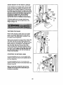
TIGHTENING THE CABLES
Woven cable, the type of cable used on the weight
system, can stretch slightlywhen it is firstused. If
there is slackin the cables before resistanceis felt,
the cables shouldbe tightened.
Slack can be removed by moving a 90mm Pulley(38)
and Cable Trap (44) toa set of holes closertothe
center ofthe two Pulley Plates (36). Remove the M10
Nylon Locknut(71) and the M10 x 47mm Bolt(61)
from the Cable Trap, the Pulley, and the Pulley
Plates. Re-attach the Pulleyand the Cable Trap to
the new set of holes in the PulleyPlates with the Bolt
and Nylon Locknut.Make sure that the Cable Trap
Is In the proper position and that the Cable and
Pulley move smoothly.
CONVERTING THE BUTTERFLY ARMS
To usethe ButterflyArms (10, 11) as butterflyarms,
insertthe LockingPins (53) intothe butterflyholesin
the Front Upright(6).
To usethe ButterflyArms (10, 11) as press arms,
insertthe LockingPins (53) intothe press holesin the
ButterflyFrame (9).
Make sure that the Locldng Plns (53) are fully
Inserted Into the same set of holes before per-
formlng any exerclses.
I
Weight
Butterfly
Holes
Weight
Weight
20
15

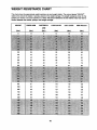
WEIGHT RESISTANCE CHART
This chart showsthe approximateweightresistanceat each weight station.The column labeled =WEIGHT"
refers to the amount ofweight, in pounds, placedon the weight carriage.The weight resistanceshownfor the
butterflyarm stationisfor each butterflyarm. Note: The actual resistance at each station may vary due to
friction between the cables, pulleys, and weight carriage.
WEIGHT
(Ibs.)
0
35
40
45
50
55
60
95
100
105
110
115
120
PRESS ARM BUTTERFLY LOW PULLEY LEG LEVER HIGH PULLEY
ARM
(Ibs.) (Ibs.) (Ibs,) (Ibs,) (Ibs.)
12 8 14 15 12
39 29 53 58 56
43 32 57 62 61
46 35 62 66 65
50 38 66 70 70
53 40 72 76 76
57 42 79 81 82
81 58 116 116 122
85 60 121 121 128
88 62 127 127 132
92 65 133 133 137
95 67 139 139 141
99 69 145 145 146
16

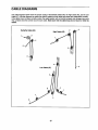
CABLE DIAGRAMS
The cable diagrams below showthe properroutingof the ButterflyCable (46), the High Cable (45), and the Low
Cable (47). Use the diagrams to make surethat thecables and the cable traps have been assembled correctly.
If the cables have not been correctlyrouted,the weight systemwill notfunction properlyand damage may occur.
The numbersshow the correct routefor each cable. Make sure that the cable traps do not touch or bind the
cables.
Butterfly Cable (46)
High Cable (45)
1
2
8
Low Cable (47)
6
4
2
1
--5
17

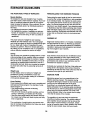
EXERCISE GUIDELINES
THE FOUR BASIC TYPES OF WORKOUTS
Muscle Building
To increasethe size and strengthof your muscles,
pushthem close to their maximum capacity.Yourmus-
cleswillcontinuallyadapt and growas you progres-
sively increasethe intensityof your exercise.You can
adjustthe intensitylevel of an individualexercise in
two ways:
• by changingthe amount of weight used
• by changingthe number of repetitionsor sets per-
formed. (A =repetition" isone completecycle ofan
exercise, such as one sit-up.A "set"isa seriesof
repetitions.)
The properamount ofweight for each exercise
depends upon the individualuser.You mustgauge
yourlimitsand selectthe amount ofweight that isright
for you. Begin with3 sets of 8 repetitionsfor each
exercise you perform. Rest for 3 minutesafter each
set. When you can complete 3 sets of 12 repetitions
withoutdifficulty,increasethe amountof weight.
Toning
You can tone your musclesby pushingthem toa mod-
erate percentage oftheir capacity.Select a moderate
amountof weightand increase the number of repeti-
tionsin each set. Complete as many sets of 15 to20
repetitionsas possiblewithoutdiscomfort.Rest for 1
minuteafter each set. Work yourmusclesby complet-
ing more sets rather than by using high amountsof
weight.
Weight Loss
To lose weight, use a low amountof weightand
increasethe numberof repetitionsineach set.
Exercise for 20 to 30 minutes, restingfor a maximum
of 30 secondsbetween sets.
Cross Training
Crosstraining isan efficientway to get a completeand
well-balanced fitness program. An example of a bal-
anced program is:
• Plan weight trainingworkoutson Monday,
Wednesday, and Friday.
• Plan 20 to 30 minutesof aerobic exercise, such as
cycling or swimming,on Tuesday and Thursday.
• Rest from bothweighttraining and aerobicexercise
for at leastone full day each week to give yourbody
time to regenerate.
The combinationof weighttraining and aerobic exer-
cise willreshape and strengthenyourbody, plusdevel-
op your heart and lungs.
PERSONALIZING YOUR EXERCISE PROGRAM
Determiningthe exact lengthoftime foreach workout,
as well as the number of repetitionsor sets completed,
is an individualmatter. Itis importantto avoidoverdo-
ingit duringthe firstfew monthsof your exercise pro-
gram. You shouldprogressat your own pace and be
sensitiveto your body'ssignals.Ifyou experience pain
or dizziness at any timewhile exercising,stop immedi-
atelyand begin coolingdown. Findout what is wrong
beforecontinuing.Remember thatadequate restand a
properdiet are importantfactorsin any exercise pro-
gram.
WARMING UP
Begin each workoutwith 5 to 10 minutesof stretching
and lightexerciseto warm up.Warming up prepares
your bodyfor more strenuousexercise by increasing
circulation,raisingyourbody temperature and deliver-
ing more oxygento yourmuscles.
WORKING OUT
Each workoutshouldinclude6 to 10 differentexercis-
es. Select exercises for every majormusclegroup,
emphasizingareas that you want todevelop most.To
give balance and varietyto yourworkouts,varythe
exercisesfrom sessionto session.
Schedule yourworkoutsfor the time ofday when your
energy level is the highest.Each workoutshouldbe
followed by at least one day of rest.Once you find the
schedule that is rightfor you, stickwith it.
EXERCISE FORM
Maintainingproperform isan essentialpart of an
effective exercise program.This requiresmoving
throughthe full rangeof motionfor each exercise, and
moving onlythe appropriatepartsof the body.
Exercisingin an uncontrolledmanner willleave you
feeling exhausted. On the exercise guide accompany-
ing this manualyou will find photographsshowingthe
correct form for several exercises, and a listofthe
muscles affected. Refer tothe muscle chart on page
19 to find the names of the muscles.
The repetitions in each set shouldbe performed
smoothlyand without pausing.The exertion stageof
each repetition should last about half as long as the
return stage. Proper breathing is important. Exhale
during the exertion stage of each repetition and inhale
during the return stroke. Never hold your breath.
18

Restfor a shortperiodof time after each set. The
ideal restingperiodsare:
• Rest for three minutes after each set for a muscle
buildingworkout.
• Rest for one minuteafter each set for a toningwork-
out.
• Rest for 30 seconds after each set for a weight loss
workout.
Plan to spend the firstcouple of weeks familiarizing
yourself withthe equipmentand learningthe proper
form for each exercise.
COOLING DOWN
End each workoutwith 5 to 10 minutesof stretching.
Includestretchesfor bothyourarms and legs. Move
slowlyas you stretchand do not bounce. Ease into
each stretchgradually and go onlyas far as you can
without strain. Stretching at the end of each workout
is an effective way to increase flexibility.
STAYING MOTIVATED
For motivation,keep a recordof each workout,listthe
date, the exercises performed,the weight used, and
the numbers of sets and repetitionscompleted.
Record yourweight and key body measurementsat
the end of every month. Remember, the key to
achievingthe greatest resultsis to make exercise a
regular and enjoyable part ofyour everyday life.
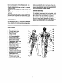
MUSCLE CHART
A. Sternomastoid(neck)
B. PectoralisMajor (chest)
C. Biceps(frontofarm)
D. Obliques(waist)
E. Brachioradials(forearm)
F. Hip Flexors(upperthigh)
G. Abductor(outerthigh)
H. Quaddceps(frontof thigh)
I. Sartorius(frontofthigh)
J. "nbialisAntedor(front ofcalf)
K. Soleus(frontofcalf)
L. RectusAbdominus(stomach)
M. Adductor(innerthigh)
N, Trapezius(upperback)
O. Rhomboideus(upperback)
P. Deltoid(shoulder)
Q. Triceps(backofarm)
R. LatissimusDorsi(mid back)
S. Spinae Erectors(lowerback)
T. GluteusMedius(hip)
U. GluteusMaximus(buttocks)
V. Hamstring(backof leg)
W. Gastrocnemius(backofcalf)
R
S
19

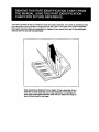
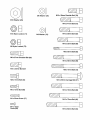
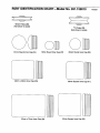
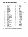
This chart is provided to helpyou identifythe small parts used in assembly.The number in parenthesisbelow
each part refersto the key number ofthe partfrom the PART LIST in the center ofthis manual. Important:
Some parts may have been pre-aesembled for shipping. If you cannot find a part In the parts bags,
check to see If It has been pre-assembled.
Note: Assembly Is divided into four stages: 1) frame assembly, 2) arm
assembly, 3) cable assembly, and 4) seat assembly. The hardware for
each stage Is packaged separately. Walt untll you begln each stage to
open the parts bag for that stage.
Page is loading ...
Page is loading ...
Page is loading ...
Page is loading ...
Page is loading ...
Page is loading ...
-
 1
1
-
 2
2
-
 3
3
-
 4
4
-
 5
5
-
 6
6
-
 7
7
-
 8
8
-
 9
9
-
 10
10
-
 11
11
-
 12
12
-
 13
13
-
 14
14
-
 15
15
-
 16
16
-
 17
17
-
 18
18
-
 19
19
-
 20
20
-
 21
21
-
 22
22
-
 23
23
-
 24
24
-
 25
25
-
 26
26


Weider 2100 User manual
- Type
- User manual
- This manual is also suitable for
Ask a question and I''ll find the answer in the document
Finding information in a document is now easier with AI
Related papers
-
Weider X2 User manual
-
-
WeiderPro PRO 9950 SYSTEM 15953 User manual
-
-
-
-
Sears 831154030 User manual
-
-
-
Other documents
-
AVF EM60S User manual
-
Weslo Gym 2500 User manual
-
Weslo Gym 1500 User manual
-
Gold's Gym XRT 75 User manual
-
Pro-Form Fusion 6.0 LX User manual
-
Epic 700 Vx User manual
-
Gold's Gym Platinum GGSY3058.0 User manual
-
-
Bodyworx HSBS280 User manual
-
NordicTrack NTSY59210 User manual