Page is loading ...
18-BC85D1-2
ALL phases of this installation must comply with NATIONAL, STATE AND LOCAL CODES
IMPORTANT — This Document is customer property and is to remain with this unit. Please return to service informa-
tion pack upon completion of work.
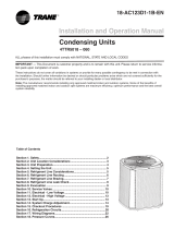
Heat Pumps
These instructions do not cover all variations in systems or provide for every possible contingency to be met in connection with
the installation. Should further information be desired or should particular problems arise which are not covered sufficiently for the
purchaser’s purposes, the matter should be referred to your installing dealer or local distributor.
Note: The manufacturer recommends installing only approved matched indoor and outdoor systems. All of the manufacture’s split
systems are AHRI rated only with TXV/EEV indoor systems. Some of the benefits of installing approved matched indoor and out-
door split systems are maximum efficiency, optimum performance and the best overall system reliability.
4TWB3018–060
Installer’s Guide
Table of Contents
Section 1. Safety ..................................................................................... 2
Section 2. Unit Location Considerations.............................................. 3
Section 3. Unit Preparation .................................................................... 5
Section 4. Setting the Unit ..................................................................... 5
Section 5. Refrigerant Line Considerations ......................................... 6
Section 6. Refrigerant Line Routing ..................................................... 7
Section 7. Refrigerant Line Brazing ...................................................... 8
Section 8. Refrigerant Line Leak Check .............................................10
Section 9. Evacuation ........................................................................... 11
Section 10. Service Valves ................................................................... 11
Section 11. Electrical - Low Voltage .................................................... 13
Section 12. Electrical - High Voltage ................................................... 16
Section 13. Start Up .............................................................................. 17
Section 14. System Charge Adjustment ............................................. 18
Section 15. Checkout Procedures and Troubleshooting ................... 23

2 18-BC85D1-2
Section 1. Safety
▲
WARNING
!
This information is intended for use by individuals
possessing adequate backgrounds of electrical and
mechanical experience. Any attempt to repair a central
air conditioning product may result in personal injury
and/or property damage. The manufacture or seller
cannot be responsible for the interpretation of this
information, nor can it assume any liability in connec-
tion with its use.
These units use R-410A refrigerant which operates
at 50 to 70% higher pressures than R-22. Use only
R-410A approved service equipment. Refrigerant
cylinders are painted a “Rose” color to indicate the
type of refrigerant and may contain a “dip” tube to
allow for charging of liquid refrigerant into the sys-
tem. All R-410A systems use a POE oil that readily
absorbs moisture from the atmosphere. To limit this
“hygroscopic” action, the system should remain sealed
whenever possible. If a system has been open to the
atmosphere for more than 4 hours, the compressor oil
must be replaced. Never break a vacuum with air and
always change the driers when opening the system
for component replacement. For specific handling
concerns with R-410A and POE oil reference Retrofit
Bulletins SS-APG006-EN and APP-APG011-EN or
APPAPG012-EN.
Extreme caution should be exercised when opening
the Liquid Line Service Valve. Turn counterclockwise
until the valve stem just touches the rolled edge. No
torque is required. Failure to follow this warning will
result in abrupt release of system charge and may
result in personal injury and /or property damage.
UNIT CONTAINS R-410A REFRIGERANT!
R-410A operating pressures exceed the limit of R-22.
Proper service equipment is required. Failure to use
proper service tools may result in equipment damage
or personal injury.
SERVICE
USE ONLY R-410A REFRIGERANT AND AP-
PROVED POE COMPRESSOR OIL.
▲
WARNING
!
▲
WARNING
!
LIVE ELECTRICAL COMPONENTS!
During installation, testing, servicing, and trouble-
shooting of this product, it may be necessary to work
with live electrical components. Failure to follow all
electrical safety precautions when exposed to live
electrical components could result in death or serious
injury.
▲
WARNING
!
If using existing refrigerant lines make certain that all
joints are brazed, not soldered.
▲
CAUTION
!
Scroll compressor dome temperatures may be hot. Do
not touch the top of compressor; it may cause minor to
severe burning.
▲
CAUTION
!
▲
WARNING
!
18-BC85D1-2 3
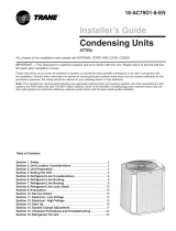
Unit Dimensions and Weight
Models H x D x W (in)
Weight* (lb)
4TWB3018D
29 x 30 x 33 160
4TWB3024D
29 x 30 x 33 160
4TWB3030C
33 x 30 x 33 193
4TWB3036C
33 x 34 x 37 198
4TWB3042B
33 x 34 x 37 219
4TWB3048B
37 x 34 x 37 234
4TWB3060B
41 x 34 x 37 248
* Weight values are estimated.
Section 2. Unit Location Considerations
2.1 Unit Dimensions and Weight
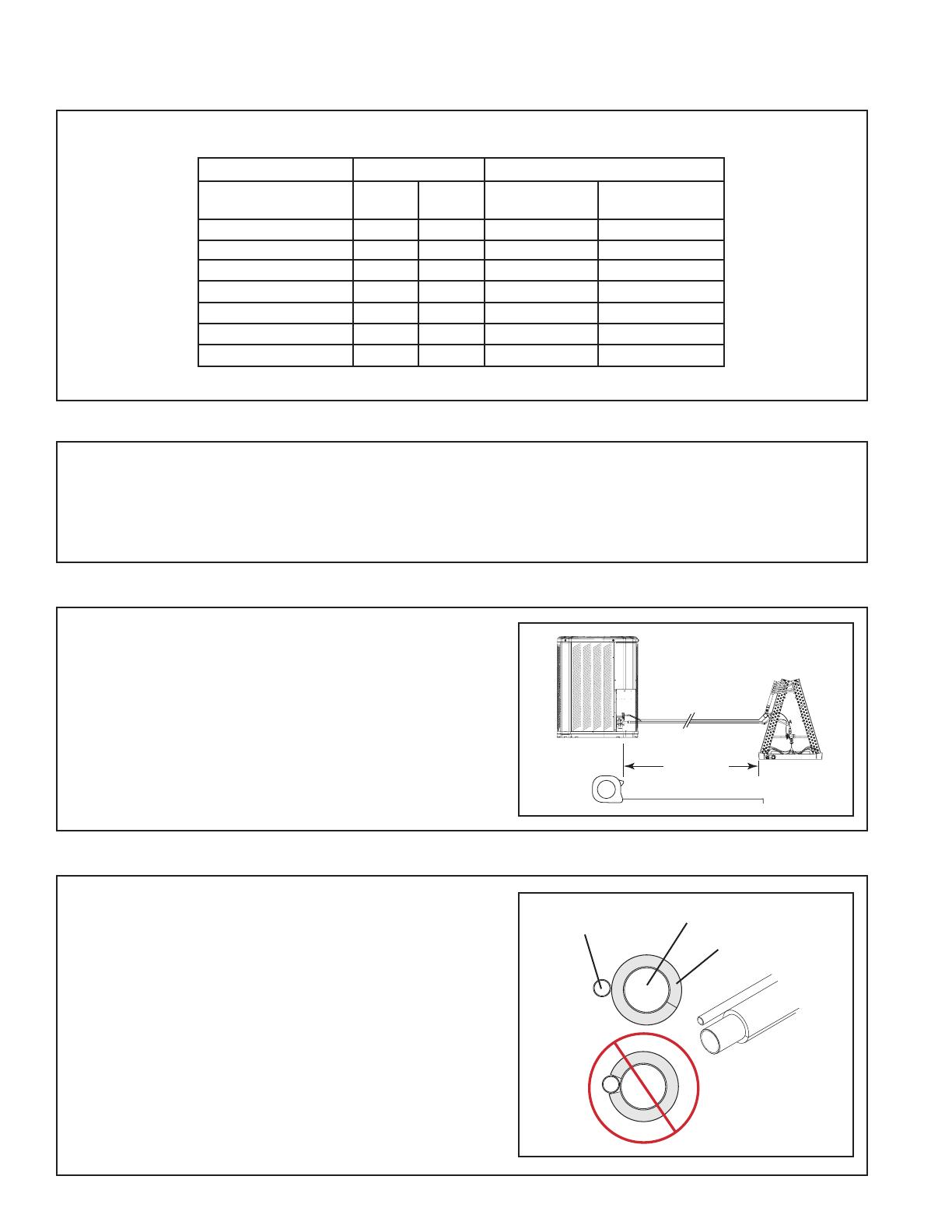
2.2 Refrigerant Piping Limits
1. The maximum length of refrigerant lines
from outdoor to indoor unit should NOT
exceed sixty (60) feet.
2. The maximum vertical change should not
exceed sixty (60) feet.
3. Service valve connection diameters are
shown in Table 5.1.
Note: For line lengths greater than sixty (60)
feet, Refer to Refrigerant Piping Application
Guide, SS-APG006-EN or Refrigerant Piping
Software Program, 32-3312-03 (or latest revi-
sion).
Table 2.1
When mounting the outdoor unit on a roof, be
sure the roof will support the unit’s weight.
Properly selected isolation is recommended to
alleviate sound or vibration transmission to the
building structure.
D
H
W
60’
Max
Vertical
Change
Standard
Line Set
60’ Max
Line Length
60’
Max
Vertical
Change
4 18-BC85D1-2
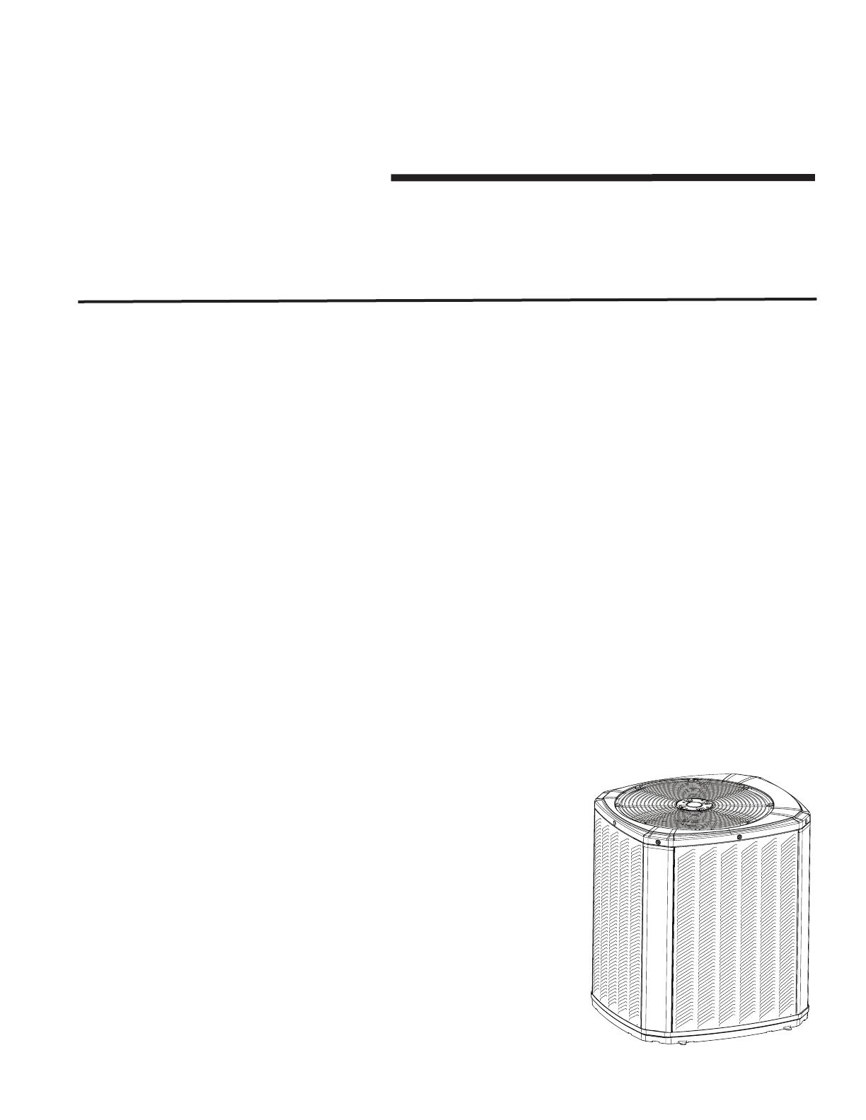
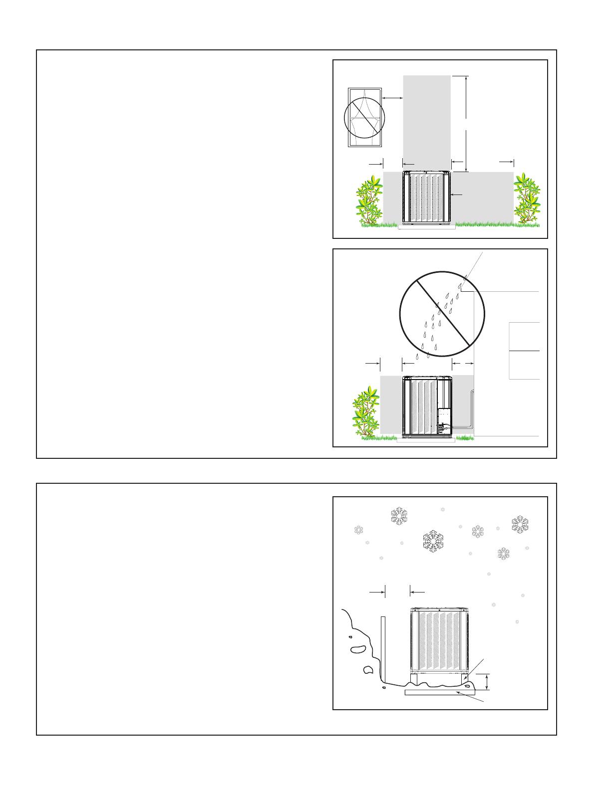
2.3 Suggested Locations for Best Reliability
2.4 Cold Climate Considerations
Ensure the top discharge area is unrestricted for
at least five (5) feet above the unit.
Three (3) feet clearance must be provided in
front of the control box (access panels) and any
other side requiring service.
It is not recommended to install in a location
where noise may distract the building occu-
pants. Some examples of these types of loca-
tions are sleeping quarters and by windows of
a living area. Please discuss location with the
building owner prior to installation.
NOTE: It is recommended that these precau-
tions be taken for units being installed in areas
where snow accumulation and prolonged below
freezing temperatures occur.
• Units should be elevated 3-12 inches above
the pad or roof top, depending on local
weather. This additional height will allow
drainage of snow and ice melted during
defrost cycle prior to its refreezing. Ensure
that drain holes in unit base pan are not
obstructed preventing draining of defrost
water.
• If possible, avoid locations that are likely to
accumulate snow drifts. If not possible, a
snow drift barrier should be installed around
the unit to prevent a build-up of snow on the
sides of the unit.
Avoid locations such as near windows where
condensation and freezing defrost vapor can
annoy a customer.
Position the outdoor unit a minimum of 12” from
any wall or surrounding shrubbery to ensure
adequate airflow.
Outdoor unit location must be far enough away
from any structure to prevent excess roof runoff
water or icicles from falling directly on the unit.
Min. 12” to
Shrubbery
Avoid Install
Near Bedrooms
Min 5’ Unrestricted
Access Panel
Min 3’
Unrestricted
Min. 12” to
Shrubbery
Min. 12”
to Wall
Min. 12”
Snow
Barrier
3-12” Elevation
Snow Legs
Pad

18-BC85D1-2 5
2.5 Coastal Considerations
STEP 2 - To remove the unit from the pallet,
remove tabs by cutting with a sharp tool.
Section 3. Unit Preparation
3.1 Prepare The Unit For Installation
STEP 1 - Check for damage and report prompt-
ly to the carrier any damage found to the unit.
Section 4. Setting the Unit
4.1 Pad Installation
When installing the unit on a support pad, such
as a concrete slab, consider the following:
• The pad should be at least 1” larger than the
unit on all sides.
• The pad must be separate from any structure.
• The pad must be level.
• The pad should be high enough above grade
to allow for drainage.
• The pad location must comply with National,
State, and Local codes.
If installed within one mile of salt water, including seacoasts and inland waterways, models without factory sup-
plied Seacoast Salt Shields require the addition of BAYSEAC001 (Seacoast Kit) at installation time.
6 18-BC85D1-2
Line Sizes Service Valve Connection Sizes
Model
Vapor
Line
Liquid
Line
Vapor Line
Connection
Liquid Line
Connection
4TWB3018D 5/8 3/8 5/8 3/8
4TWB3024D 5/8 3/8 5/8 3/8
4TWB3030C 3/4 3/8 3/4 3/8
4TWB3036C 3/4 3/8 3/4 3/8
4TWB3042B 3/4 3/8 3/4 3/8
4TWB3048B 7/8 3/8 7/8 3/8
4TWB3060B 7/8 3/8 7/8 3/8
Section 5. Refrigerant Line Considerations
5.1 Refrigerant Line and Service Valve Connection Sizes
Table 5.1
5.3 Required Refrigerant Line Length
5.2 Factory Charge
5.4 Refrigerant Line Insulation
Important: The Vapor Line must always be
insulated. DO NOT allow the Liquid Line and
Vapor Line to come in direct (metal to metal)
contact.
Vapor Line
Liquid Line
Insulation
Determine required line length and lift. You will
need this later in STEP 2 of Section 14.
Total Line Length = __________ Ft.
Total Vertical Change (lift) = __________ Ft.
Outdoor condensing units are factory charged with the system charge required for the outdoor condensing unit,
fifteen (15) feet of tested connecting line, and the smallest indoor evaporative coil match. If connecting line
length exceeds fifteen (15) feet and/or a larger indoor evaporative coil is installed, then final refrigerant
charge adjustment is necessary.
Line Length
18-BC85D1-2 7
5.5 Reuse Existing Refrigerant Lines
For retrofit applications, where the existing
indoor evaporator coil and/or refrigerant lines
will be used, the following precautions should
be taken:
• Ensure that the indoor evaporator coil and
refrigerant lines are the correct size.
• Ensure that the refrigerant lines are free of
leaks, acid, and oil.
Important: For more information see publica-
tion numbers SS-APG006-EN.
▲
CAUTION
!
If using existing refrigerant lines make certain that
all joints are brazed, not soldered.
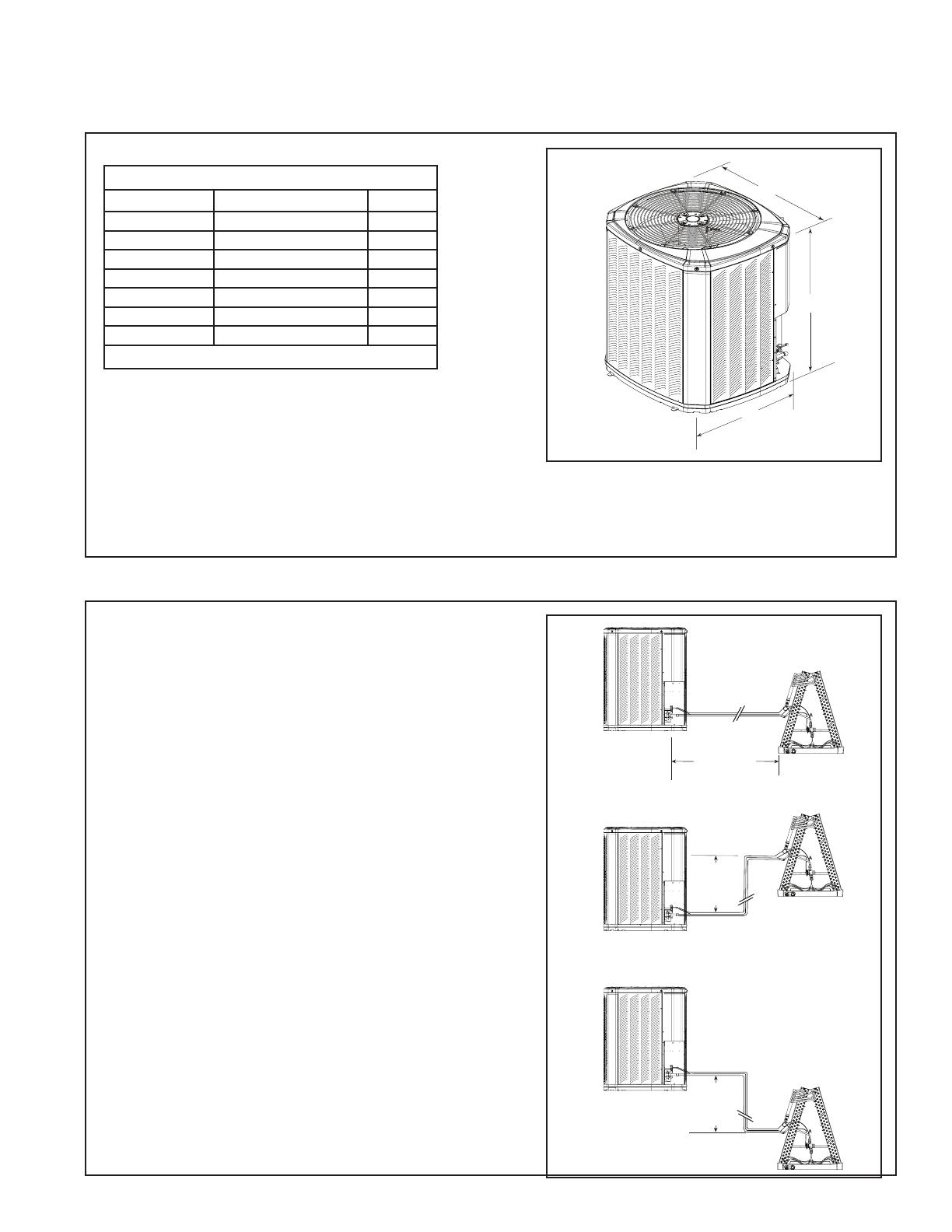
Section 6. Refrigerant Line Routing
6.1 Precautions
Important: Take precautions to prevent noise
within the building structure due to vibration
transmission from the refrigerant lines.
For Example:
• When the refrigerant lines have to be fastened to floor joists or other framing in a structure, use isolation type
hangers.
• Isolation hangers should also be used when refrigerant lines are run in stud spaces or enclosed ceilings.
• Where the refrigerant lines run through a wall or sill, they should be insulated and isolated.
• Isolate the lines from all ductwork.
• Minimize the number of 90º turns.
Comply with National, State, and Local Codes when
isolating line sets from joists, rafters, walls, or other
structural elements.
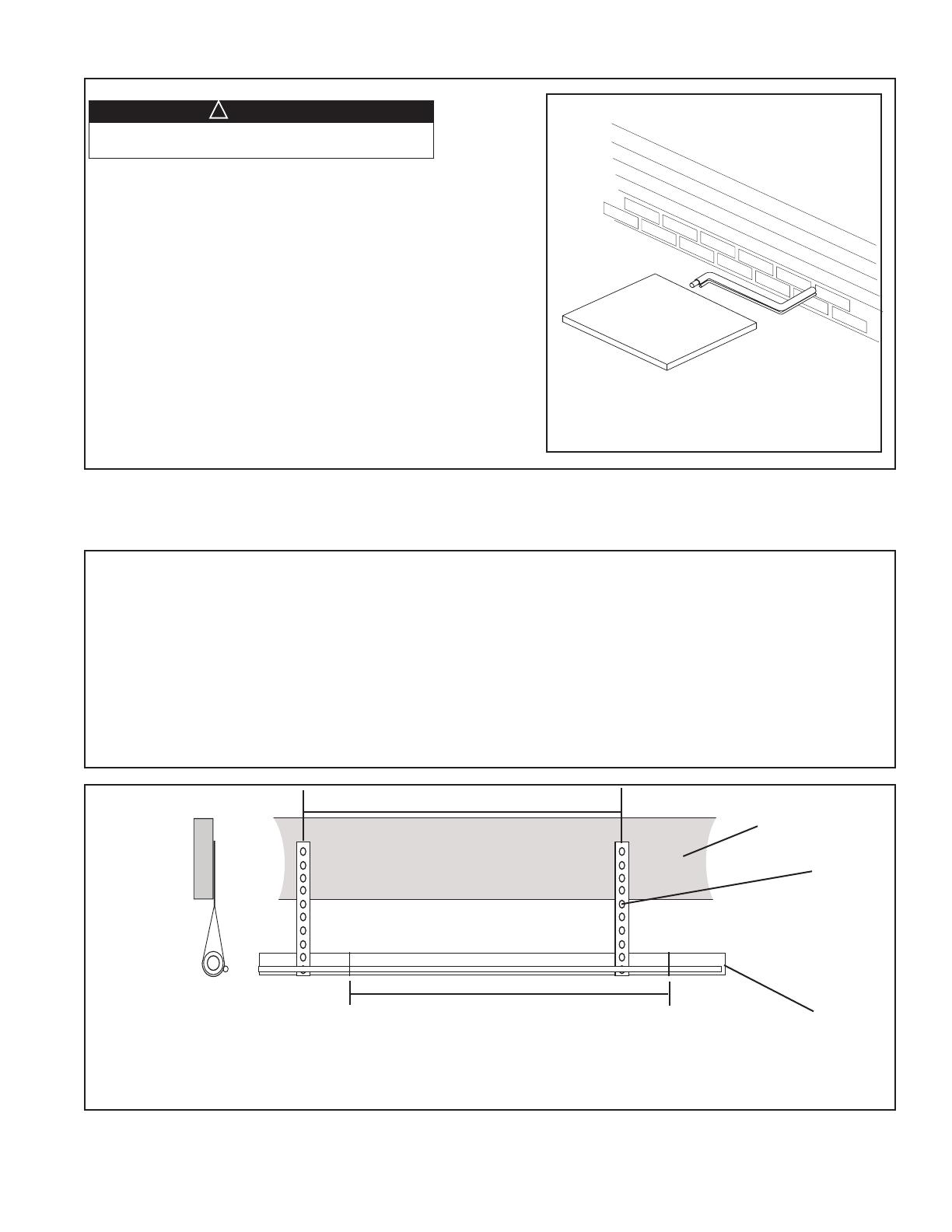
Isolation From Joist/Rafter
Side View
8 Feet Maximum
Secure Vapor line from joists using isolators every 8 ft. Secure
Liquid Line directly to Vapor line using tape, wire, or other appro-
priate method every 8 ft.
Joist/Rafter
Isolator
Line Set
8 Feet Maximum
8 18-BC85D1-2
Isolation In Wall Spaces
Side View
Wall
Isolator
Line Set
8 Feet Maximum
Secure Vapor Line using isolators every 8 ft. Secure Liquid Line
directly to Vapor Line using tape, wire, or other appropriate
method every 8 ft.
8 Feet Maximum
Isolation Through Wall
DO NOT hang line sets from ductwork
Sealant
Insulation
Vapor Line
Wall
Ductwork
Isolator
Line Set
Section 7. Refrigerant Line Brazing
7.1 Braze The Refrigerant Lines
STEP 1 - Remove caps or plugs. Use a debur-
ing tool to debur the pipe ends. Clean both
internal and external surfaces of the tubing
using an emery cloth.
18-BC85D1-2 9
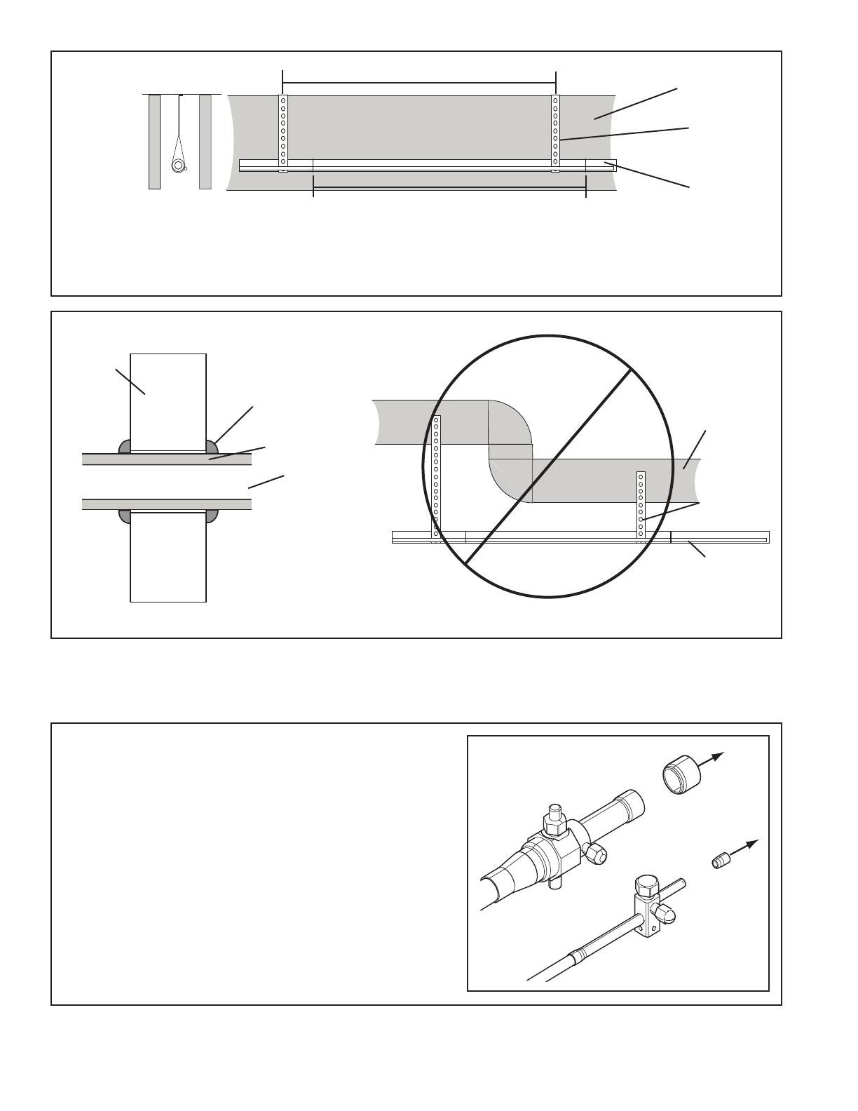
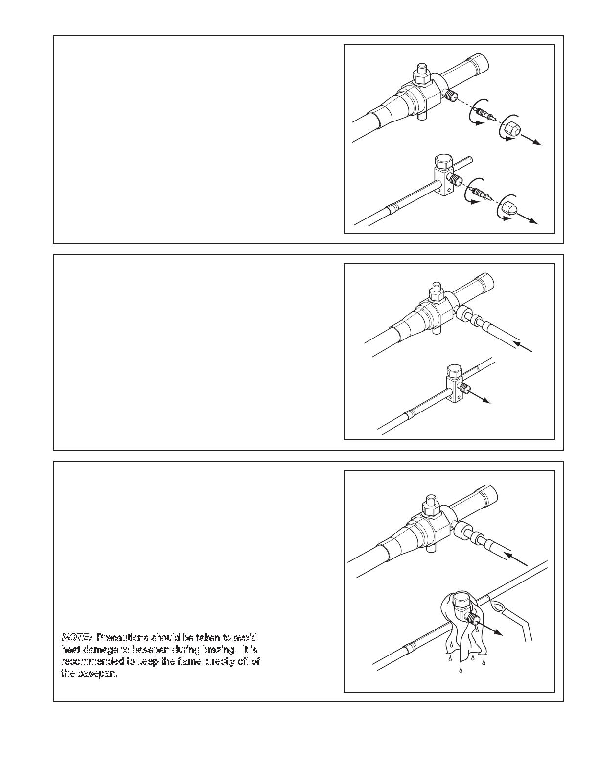
STEP 2 - Remove the pressure tap cap and
valve cores from both service valves.
STEP 3 - Purge the refrigerant lines and indoor
coil with dry nitrogen.
STEP 4 - Wrap a wet rag around the valve
body to avoid heat damage and continue the
dry nitrogen purge.
Braze the refrigerant lines to the service
valves.
Continue the dry nitrogen purge. Do not re-
move the wet rag until all brazing is completed.
Important: Remove the wet rag before stopping
the dry nitrogen purge.
NOTE: Precautions should be taken to avoid
heat damage to basepan during brazing. It is
recommended to keep the flame directly off of
the basepan.
10 18-BC85D1-2
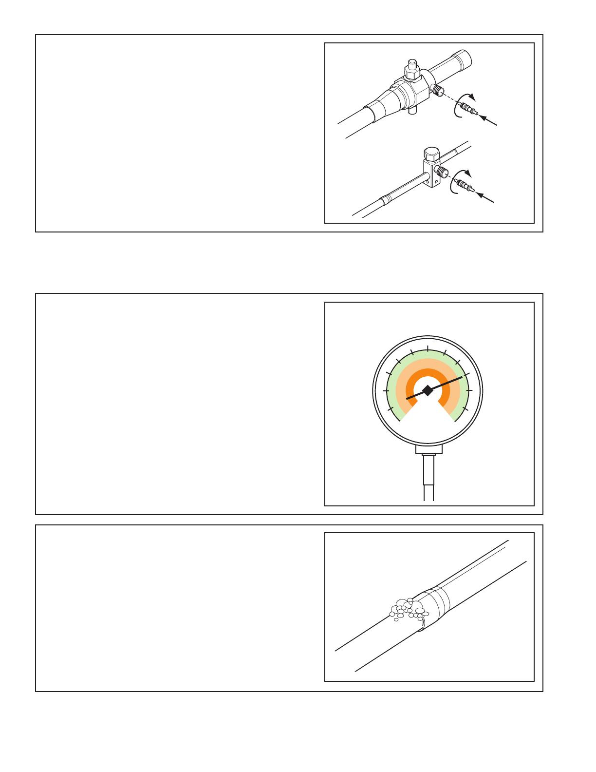
STEP 5 - Replace the pressure tap valve cores
after the service valves have cooled.
STEP 2 - Check for leaks by using a soapy solu-
tion or bubbles at each brazed location.
Remove nitrogren pressure and repair any leaks
before continuing.
Section 8. Refrigerant Line Leak Check
8.1 Check For Leaks
STEP 1 - Pressurize the refrigerant lines and
evaporator coil to 150 PSIG using dry nitrogen.
150 PSIG
18-BC85D1-2 11
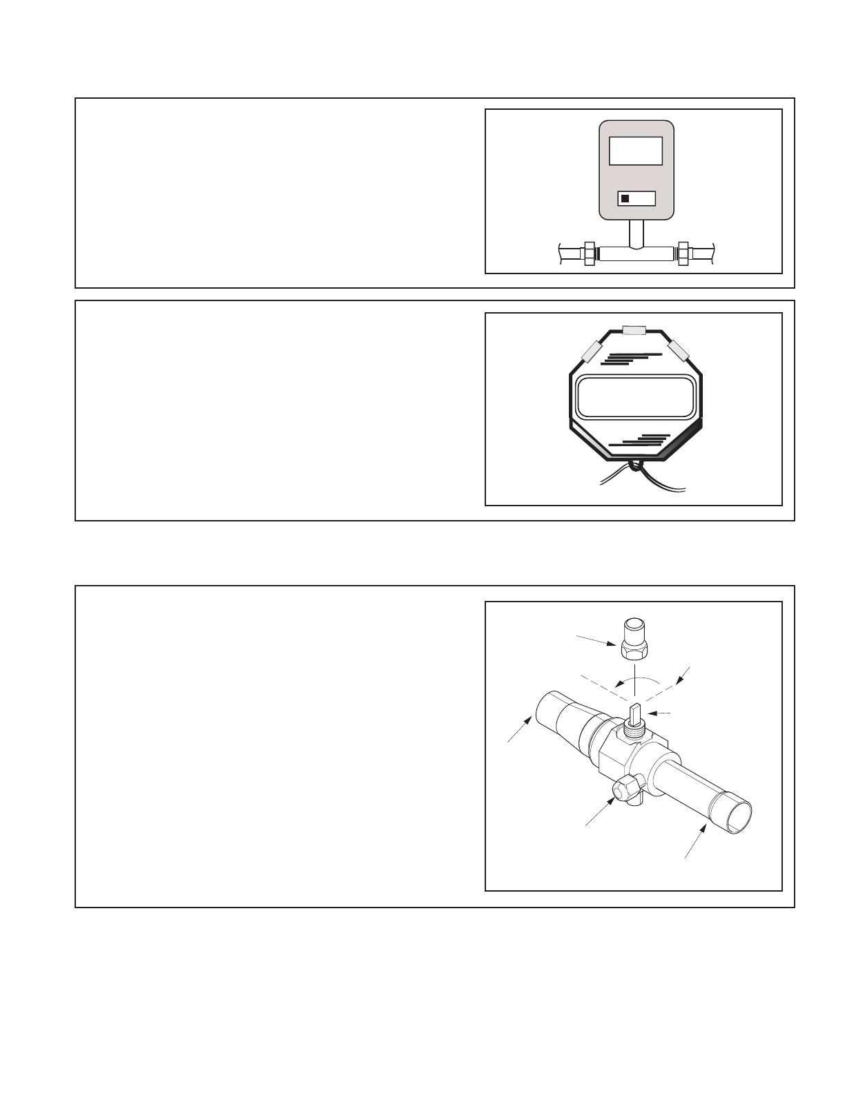
Section 9. Evacuation
9.1 Evacuate the Refrigerant Lines and Indoor Coil
Important: Do not open the service valves until
the refrigerant lines and indoor coil leak check
and evacuation are complete.
STEP 1 - Evacuate until the micron gauge reads
no higher than 350 microns, then close off the
valve to the vacuum pump.
STEP 2 - Observe the micron gauge. Evacuation
is complete if the micron gauge does not rise
above 500 microns in one (1) minute.
Once evacuation is complete blank off the
vacuum pump and micron gauge, and close the
valves on the manifold gauge set.
1 MIN.
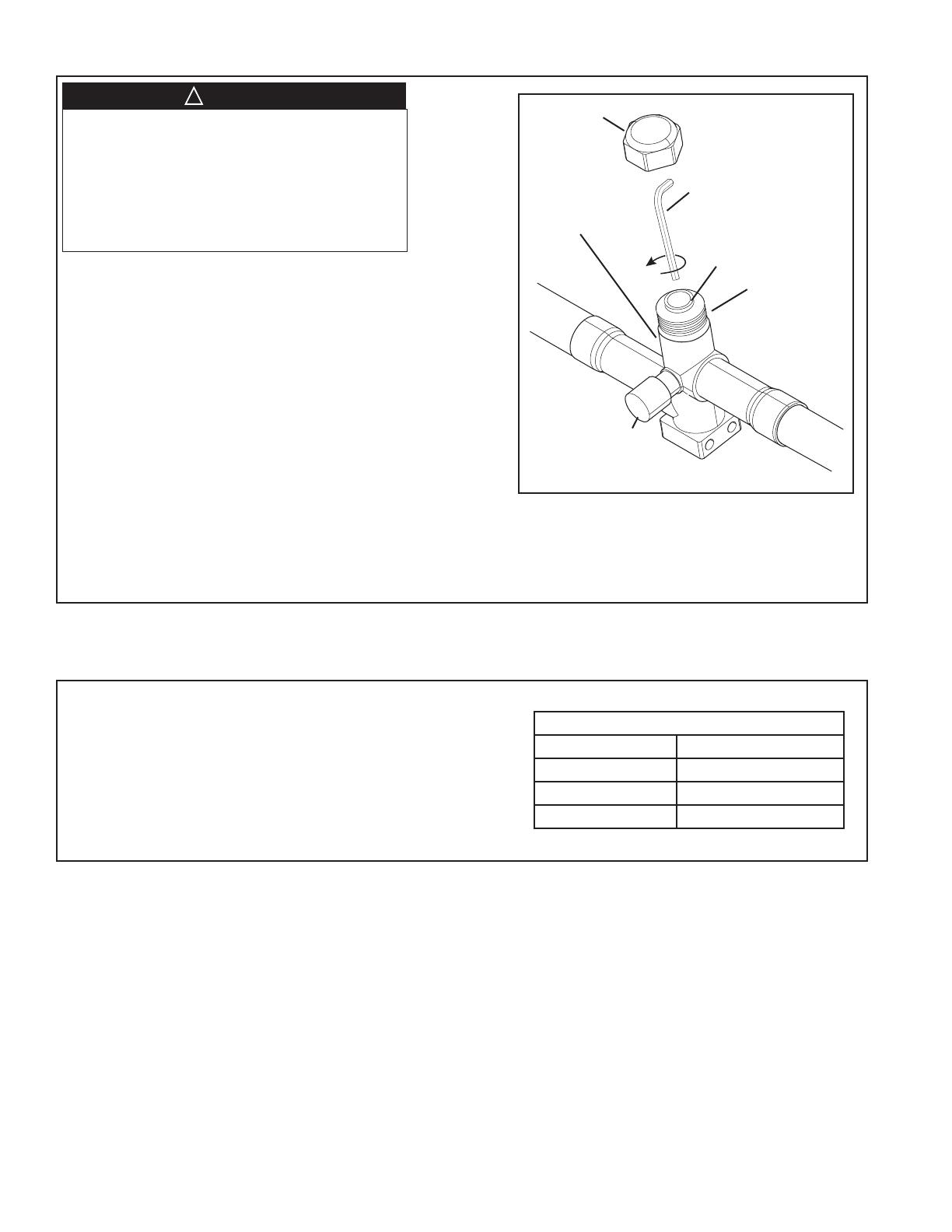
Section 10. Service Valves
10.1 Open the Gas Service Valve
0350
Microns
ON
OFF
CAP
1/4 TURN ONLY
COUNTERCLOCKWISE
FOR FULL OPEN
POSITION
VALVE STEM
GAS LINE CONNECTION
UNIT SIDE
OF VALVE
PRESSURE TAP PORT
Important: Leak check and evacuation must be
completed before opening the service valves.
NOTE: Do not vent refrigerant gases into the
atmosphere.
STEP 1 - Remove valve stem cap.
STEP 2 - Using an adjustable wrench, turn valve
stem 1/4 turn counterclockwise to the fully open
position.
STEP 3 - Replace the valve stem cap to prevent
leaks. Tighten finger tight plus an additional 1/6
turn.
12 18-BC85D1-2
10.1 Open the Liquid Service Valve
Important: Leak check and evacuation must be
completed before opening the service valves.
STEP 1 - Remove service valve cap.
STEP 2 - Fully insert 3/16” hex wrench into the
stem and back out counterclockwise until valve
stem just touches the rolled edge (approximately
five (5) turns.)
STEP 3 - Replace the valve cap to prevent leaks.
Tighten finger tight plus an additional 1/6 turn.
Cap
Rolled Edge to
Captivate Stem
Hex Headed
Valve System
Service Port
3/16” Hex Wrench
Unit Side
of Service
Valve
Extreme caution should be exercised when
opening the Liquid Line Service Valve. Turn
counterclockwise until the valve stem just
touches the rolled edge. No torque is required.
Failure to follow this warning will result in abrupt
release of system charge and may result in
personal injury and /or property damage.
▲
WARNING
!
Section 11. Electrical - Low Voltage
11.1 Low Voltage Maximum Wire Length
Table 11.1 defines the maximum total length of
low voltage wiring from the outdoor unit, to the
indoor unit, and to the thermostat.
Table 11.1
24 VOLTS
WIRE SIZE MAX. WIRE LENGTH
18 AWG 150 Ft.
16 AWG 225 Ft.
14 AWG 300 Ft.

18-BC85D1-2 13
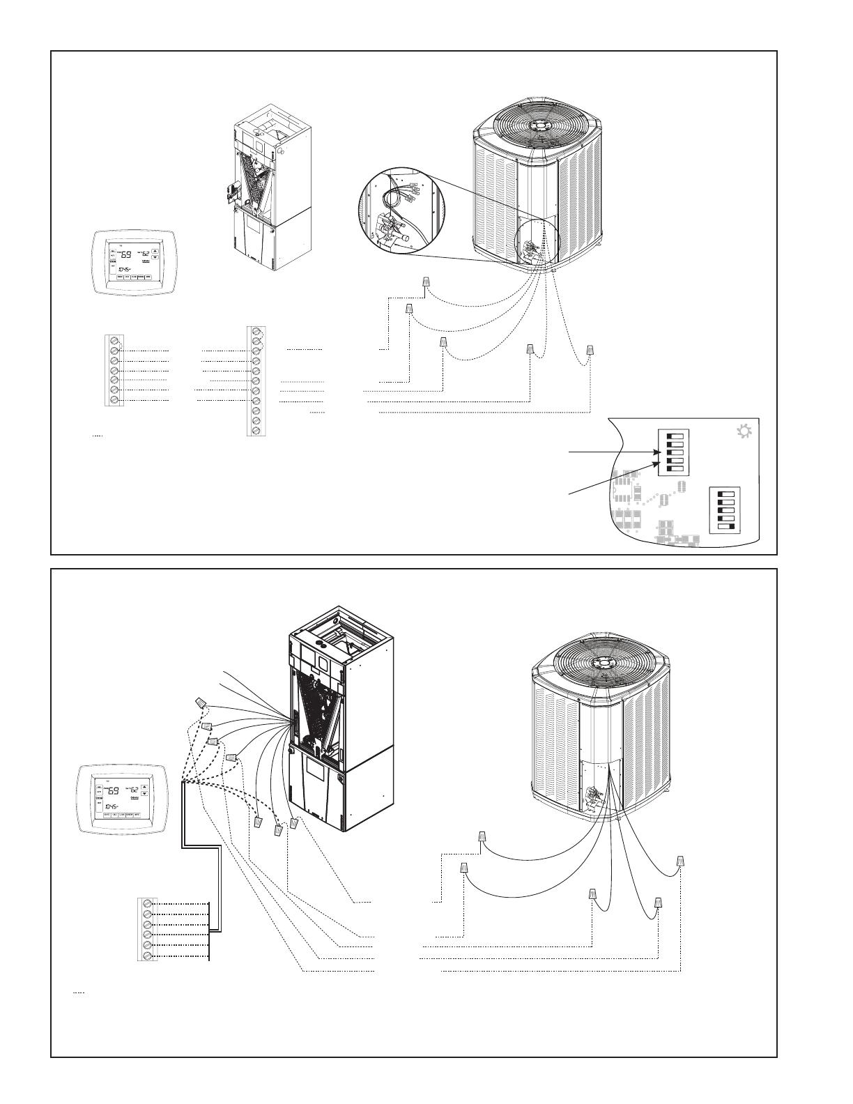
11.2 Low Voltage Hook-up Diagrams
Notes:
1. See User Interface 24
V Mode setup menu
for control mode and
cooling CFM options.
2. W3 terminal may not
be present on unit.
3. (Air Handlers only) If
electric heat does not
have 3rd contac-
tor (CH), connect
a jumper wire from
W3 to W2. If electric
heat does not have
2nd contactor (BH),
connect a jumper wire
from W2 to W1.
4. W1 - X2 is a field
installed jumper.
Communicating Indoor Unit
with 24 V Control Hook-up
Diagram
Notes:
1. Comfort control must
be dual fuel capable
or use accessory
TAYPLUS103A.
2. Ylo and BK may not be
present on unit.
3. W1 - X2 is a field
installed jumper.
Variable Speed Furnace
Hook-up Diagram
Red
Yellow
Green
White
Blue
Orange
W1
O
B
X2
G
Y1
Yellow
Yellow
Blue
Orange
Blue
Black
(X2)
Red
Red
Orange
R
Comfort Control
Variable Speed
Furnace
Heat Pump
Black
W1
W2
G
Y
B
O
BK
Y
LO
R
Neatly bundle all low voltage
wires as shown.
Red
Yellow
Green
White
Blue
Orange
W1
O
B
X2
G
Y1
Yellow
Yellow
Blue
Orange
Blue
Black
(X2)
Red
Red
Orange
R
Comfort Control
Comm. Variable Speed
Furnace or Air Handler
Heat Pump
Black
W1
W2
W3
G
Y2
B
O
BK
D
Y1
R
Neatly bundle all low voltage
wires as shown.
14 18-BC85D1-2
TAM7 Air Handler
Hook-up Diagram
TAM4 Air Handler
Hook-up Diagram
1
1
12345
12345
HP
2(Compressor)
2(Stages)
AC (S ystem)
}
OUTDOOR
Capacity (Tons)
OUTDOOR
}
Torque
CFM/Ton
Cool Of fDelay
}
INDOOR
CFM
+12V
R13
R14
R1
R4
1
U1
RNET 1
S1
on
on
S2
RNET 2
R
6
C22
C19
C
15
C
12
C18
C21
C10
D9
L1
R22
Must configure to
“OFF” for HP Units.
Must configure to “OFF” for
single-stage compressors.
Control Board
Comfort Control
Field wiring
Yellow
Green
White
Blue
B
W
G
Y
R
Red
O
Orange
Yellow
Blue
Black
(X2)
Red
Orange
Heat Pump
B - Blue
Y - Yellow
R - Red
O - Orange
W1 - White
Air Handler
Red
Blue
Yellow YI
Purple YO
Orange
Green
W2 Pink
W3 Brown
W1 White *
• * For multiple stages of electric heat, jumper W1, W2, and W3 together if comfort control has only one stage of heat
• YI and YO connections must be made as shown for proper operation, freeze protection, and internally mounted condensate
overflow circuits to work properly
• Internally mounted condensate switch is optional and must be ordered separately
• If a 3rd party condensate overflow switch is installed, it should be wired between Y of the thermostat and YI of the EEV control.
• Some models have a terminal strip. Refer to air handler Installer’s Guide.
Comfort Control
Air Handler
Heat Pump
Neatly bundle all low voltage
wires as shown.
Field wiring
Yellow
Blue
Black
(X2)
Red
Orange
Red
Yellow
Orange
Green
White
Blue
B
B - Blue
W
X2
G
Y1
Y1 - Yellow
R
O
O
R
B
YI
W1
YO
DH/BK
G
W2
W3
R - Red
O - Orange
(In)
(Out)
W1 - White

18-BC85D1-2 15
GAM5 Air Handler
Hook-up Diagram
GAM2 Air Handler
Hook-up Diagram
Red
Yellow
Green
White
Blue
Orange
Yellow
Green
White
Blue
B
B - Blue
R - Red
W
G
Y
Y - Yellow
R
Red
O
Orange
Comfort Control
Air Handler
Field wiring
Yellow
Blue
Black
(X2)
Red
Orange
Heat Pump
Red
Blue
Green
W2 Pink
W3 Brown
W1 White
Yellow
• * For multiple stages of electric heat, jumper W1, W2, and W3 together if comfort control has only one stage of heat
• Some models have a terminal strip. Refer to air handler Installer’s Guide.
Red
Yellow
Green
White
Blue
Orange
Yellow
Green
White
Blue
B
B - Blue
R - Red
W
G
Y
Y - Yellow
R
Red
O
Orange
Comfort Control
Air Handler
Field wiring
Yellow
Blue
Black
(X2)
Red
Orange
Heat Pump
Red
Blue
Green
W2 Pink
W3 Brown
W1 White
• * For multiple stages of electric heat, jumper W1, W2, and W3 together if comfort control has only one stage of heat

16 18-BC85D1-2
GAF2-36M Air Handler
Hook-up Diagram
GAF2 Air Handler
Hook-up Diagram
Comfort Control
Field wiring
Yellow
Green
White
Blue
B
W
G
Y
R
Red
O
Orange
Yellow
Blue
Black
(X2)
Red
Orange
Heat Pump
Air Handler
Red
Blue
Yellow YI
Purple YO
Orange
Green
White
• YI and YO connections must be made as shown
• Internally mounted condensate switch is optional and must be ordered separately
• If a 3rd party condensate overflow switch is installed, it should be wired between Y of the thermostat and YI of the EEV control.
Red
Yellow
Green
White
Blue
Orange
Yellow
Green
White
Blue
B
B - Blue
R - Red
W
G
Y
Y - Yellow
R
Red
O
Orange
Comfort Control
Air Handler
Field wiring
Yellow
Blue
Black
(X2)
Red
Orange
Heat Pump
Red
Blue
Green
W1 White
18-BC85D1-2 17
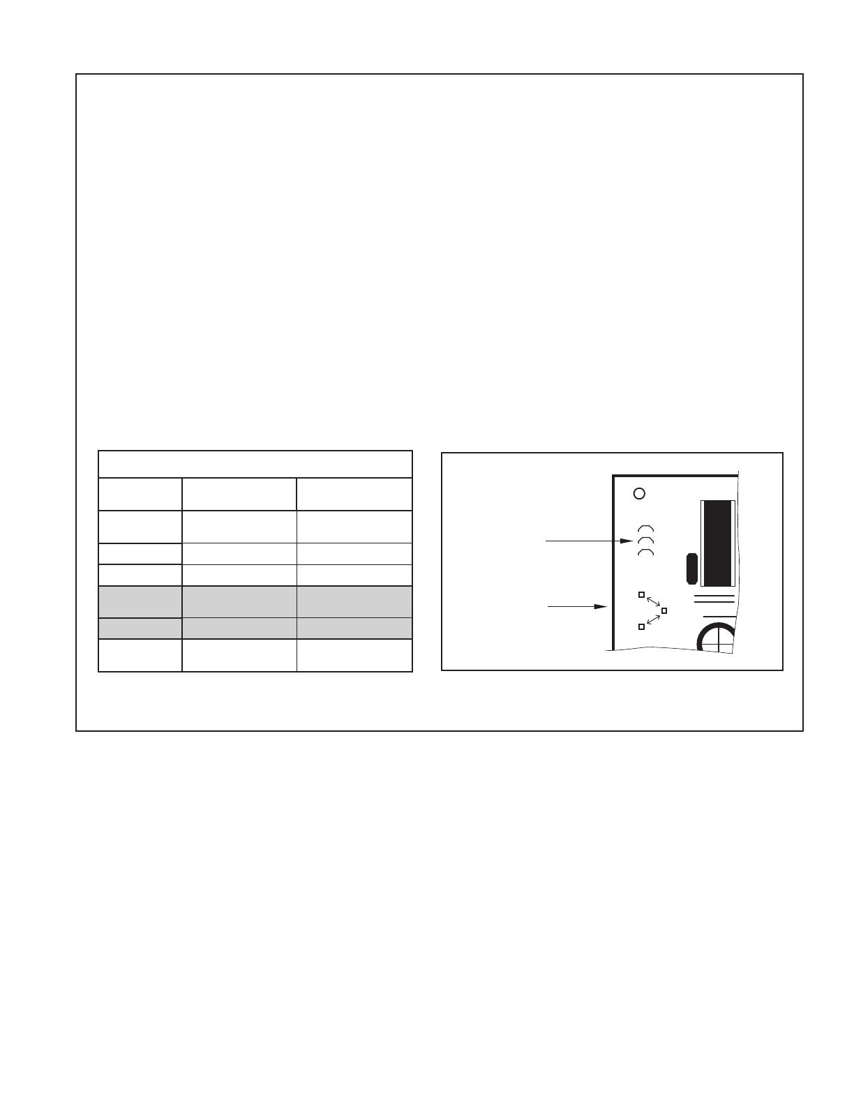
11.3 Defrost Control
Defrost controls have a selectable termination temperature. As shipped, defrost will terminate at 47°F. For a
higher termination temperature, cut Jumper J2 to achieve 70°F when at or below 30°F ambient. See Service
Facts shipped in the outdoor unit for more information.
Pin Identification (See Illustration at right)
1. TEST_COMMON (Shorting any of the other pins to this pin causes the function of the other pin to be
executed. Leaving this pin open results in the normal mode of operation.)
2. TST = Test (Shorting TEST_COMMON to this pin speeds up all defrost board timings.)
3. FRC_DFT = Forced Defrost (Short TEST_COMMON to this pin for two (2) seconds to initiate a forced
defrost. Remove the short after defrost initiates.)
Defrost Control Checkout
Normal operation requires:
• LED on board flashing 1 time/second.
• 24V AC between R & B.
• 24V AC between Y & B with unit operating.
• Defrost initiation when FRC_DFT pin is shorted to TEST_COMMON pin.
If a defrost control problem is suspected, refer to the service information in control box.
Defrost Termination Temperatures
Outdoor
Temperature
Termination
Temperature
As
Shipped
>22°F 47°F
10°F–22°F ODT + 25°F
6°F–10°F 35°F
Cut
Jumper 2
>30°F 47°F
6°F–30°F 70°F
All < 6°F
12 min. or 35°F
every 3 hrs.
Defrost Board
Detail
J1
U1
J2
J3
FRC_DFT
TST
TEST_COMMON
JUMPER 2
TEST PINS
18 18-BC85D1-2
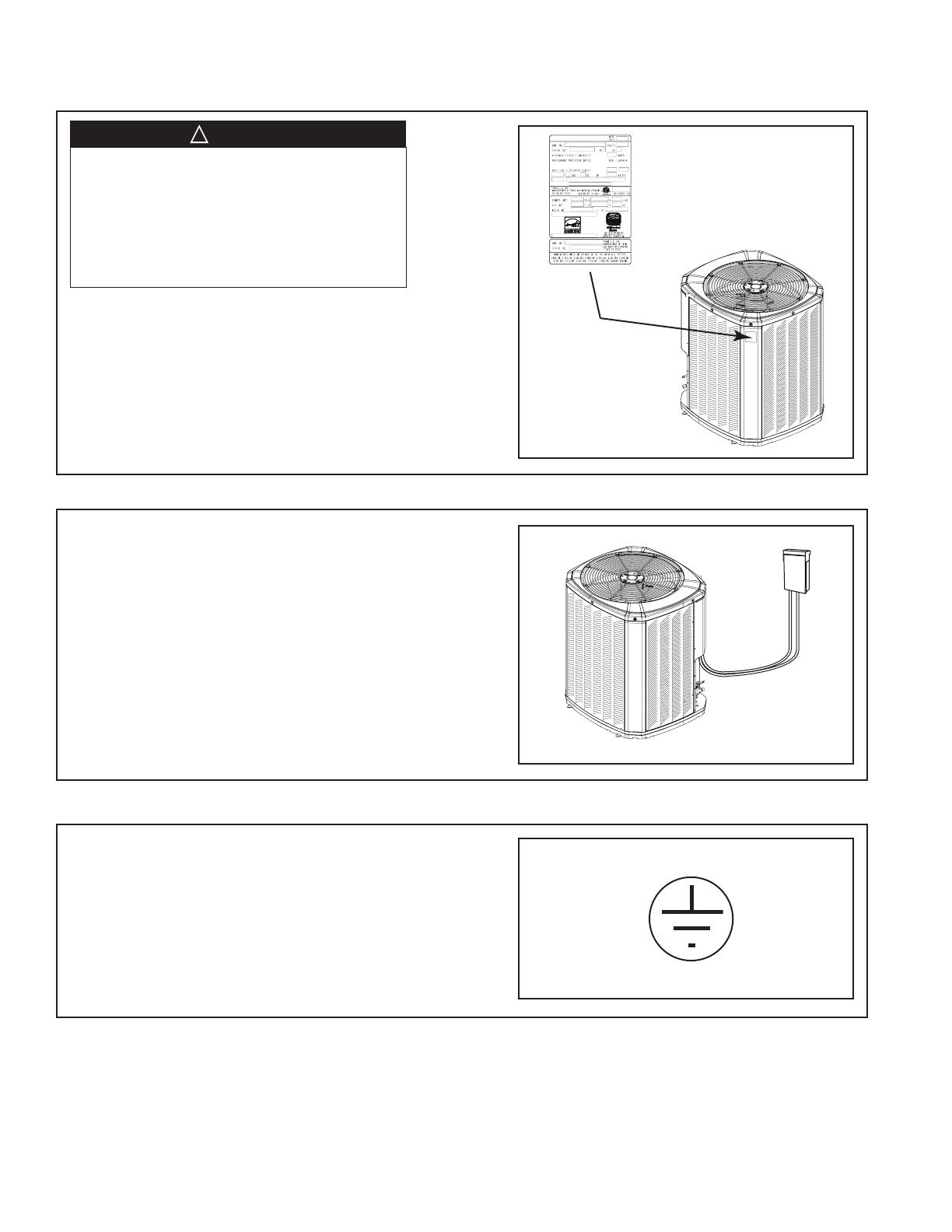
Section 12. Electrical - High Voltage
12.1 High Voltage Power Supply
The high voltage power supply must agree with
the equipment nameplate.
Power wiring must comply with national, state,
and local codes.
Follow instructions on unit wiring diagram located
on the inside of the control box cover and in the
Service Facts document included with the unit.
12.2 High Voltage Disconnect Switch
12.3 High Voltage Ground
Ground the outdoor unit per national, state, and
local code requirements.
LIVE ELECTRICAL COMPONENTS!
During installation, testing, servicing, and
troubleshooting of this product, it may be nec-
essary to work with live electrical components.
Failure to follow all electrical safety precau-
tions when exposed to live electrical compo-
nents could result in death or serious injury.
▲
WARNING
!
Install a separate disconnect switch at the
outdoor unit.
For high voltage connections, flexible electri-
cal conduit is recommended whenever vibra-
tion transmission may create a noise problem
within the structure.

18-BC85D1-2 19
Section 13. Start Up
13.1 System Start Up
STEP 2 - Set System Thermostat to OFF.
STEP 3 - Turn on disconnect(s) to apply power
to the indoor and outdoor units.
STEP 5 - Set system thermostat to ON.
OFF
D
O
N
E
CANCEL
ON
OFF
STEP 4 - Wait one (1) hour before starting the
unit if compressor crankcase heater acces-
sory is used and the Outdoor Ambient is below
70ºF.
60 MIN.
STEP 1 - Ensure Sections 7 through 12 have
been completed.
ON
D
O
N
E
CANCEL

20 18-BC85D1-2
STEP 1 - Check the outdoor temperatures.
Subcooling (in cooling mode) is the only recom-
mended method of charging above 55º F ambi-
ent outdoor temperature. See Section 14.2.
For outdoor temperatures below 55º F, see Sec-
tion 14.3.
Note: It is important to return in the spring or
summer to accurately charge the system in the
cooling mode when outdoor ambient tempera-
ture is above 55º F.
For best results the indoor temperature should
be kept between 70º F to 80º F.
Section 14. System Charge Adjustment
14.1 Temperature Measurements
14.2 Subcooling Charging in Cooling (Above 55º F Outdoor Temp.)
Indoor Temp
80º F
70º F
Outdoor Temp 1
55º F
120º F
Outdoor Temp 2
See Section 14.3 for
Outdoor
Temperatures
Below 55º F
See Section 14.2 for
Outdoor
Temperatures
Above 55º F
55º F
STEP 1 - Use the refrigerant line total length
and lift measurements from Section 5.3.
Total Line Length = __________ Ft.
Vertical Change (Lift) = __________ Ft.
LIFT
/