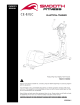
BENEFIT E420
CROSSTRAINER
93101

Box Spanner (1)
Allen Key-6mm*(1)
Screwdriver (1)13.15
NO:Q-2 Acorn Nut for M8 Bolt (8)
NO:Q Carriage Bolt M8 NO:Q-1
Carriage Bolt M8
Screwdriver (1)14.24

2
NO:Q-4 Allen Bolt (movable handlebar)
(2)
NO:Q-3 Curved Washer (8) NO:Q-8 Allen Bolt (6)
NO:Q-6 Regular Washer (4)
NO:Q-12
Screw M4*20L (4)
NO:Q-13
Screw M3*14L (4) NO:Q-11 Cap (2) NO:Q-9
Regular Washer (6)
NO:Q-10
Spring Washer ? 6(6)
NO:Q-5 lock nut for M8 (2)
NO:Q-7 Knobs(8)

1
Assembly Diagram

1
EXPLODED DIAGRAM

1
PARTS LIST AND TOOLS
NO Description Q’ty
A Computer 1
A1 Screws For computer 4
B Front handlebar 1
B1 Hand pulse 1
B2 Hand pulse wire 1
B3 Upper sensor 2
B4 Foam grip for front handlebar 1
B5 End cap for front handlebar 2
C Upper handlebar (R&L) 2
C1 End cap for Upper handlebar 2
C2 Foam grip for upper handlebar 2
D Handlebar post 1
D1 Bushingφ26.7xφ17.12x15L for handlebar post 2
D2 Tension control w/ upper cable 1
D3 Screws M5xP0.8x14L 2
D4 Middle sensor wire 1
E Allen bolt M8*P1.25*16L 7
E1 Spring washerφ8.1*φ12.9*2.4T 4
E2 Washersφ8xφ19x2t 7
F Down handlebar (R& L) 2
F1 Bushingφ26.7xφ17.12x15L for down handlebar 4
F2 Plastic washersφ10xφ25x0.5t 2
F3 Flat washersφ10xφ26x2t 2
F4 Screws M8xP1.0x20L 2
F5 Wave washersφ17.5xφ25x0.3t 2
F6 Flat washersφ12xφ19x1t 4
F7 Wave washers φ12.5xφ18x0.3t 2
F8 Bushingφ8*φ11.83*38.8L 2
F9 Sleeve φ12xφ16 4
F10 C-Type ring φ12 4
F11 Fixed grab rail 1
G Main frame 1
G1 Sensor box 1
H Shaft 1
H1 Screws M8xP1.25x12Lx5t 3
H2 Pulley wheel 1
K Front stabilizer 1
K1 Transport wheel for front stabilizer 2
L Rear stabilizer 1

2
L1 End cap for rear stabilizer 2
M Nut M10xP1.25x10T 2
M1 Crank (L) 1
M2 C-Type ringφ20 1
M3 Flat washersφ20.3xφ30x1t 1
M4 Wave washers φ20xφ30x0.3t 1
M5 Bearing 2
M6 Belt 1
M7 Chain cover ( Left) 1
M8 Screws 3/16” 6
M9 Screws M4x50L 5
M10 Chain cover( Right) 1
M11 Crank (R ) 1
M12 Tension cable (Down) 1
N Pedal post (Lift) 1
N1 Pedal post (Right) 1
N2 Plastic washers φ15xφ25x0.5T 4
N3 Flat washersφ14.3xφ25x2t 2
N4 Spring washersφ14.5*φ19.5*2.5T 2
N5 Nylon nut (Blue) 9/16"x6t 2
N6 Nylon nut (Blue) 9/16"x6t 1
N7 Pedal hinge bolt (Right) 1
N8 Pedal connecting sheet 2
N9 Bushing φ26.7xφ17.12x15L 4
N10 Wave washersφ17.5xφ25x0.3t 4
N11 Flat washers φ17.5xφ25x0.3t 1
N12 C-Type ring φ17 4
N13 Pedal hinge bolt (Left) 1
N14 Screws M5x14L 4
N15 Nylon nut (Red) 9/16"x6t
O Pedal 1
O1 Bottle holder 1
O2 Rear cover(Left / Upper) for pedal post 1
O3 Rear Cover(Left / Down) for pedal post 1
O4 Rear Cover(Right / Upper) for pedal post 1
O5 Rear Cover(Right / Down) for pedal post 1
O6 Front Cover (Left) for pedal post 2
O7 Front Cover(Right) for pedal post 2
Q~Q13 Bolts & nuts pack 1
R~R4 Magnetic Set 1
S1~S9 Flywheel set 1
T1~T11 Idler set 1

3
ASSEMBLY INSTRUCTION
NO:Q Carriage Bolt M8
NO:Q-3 Curved Washer (8)
NO:Q-2 Acorn Nut for M8 Bolt (8)
STEP 1
1. Install the front stabilizer (pt.K) with 2 carriage
bolts(pt.Q), semicircle washers (pt.Q3) and nuts
(pt.Q2) by using the hand tools. Make sure the
transportation wheels(pt.K1) are in correct
direction.
2. Assemble the Rear Stabilizer (pt.L) with 2
carriage bolts (pt.Q), semicircle washers (pt.Q3)
and nuts(pt.Q2) by using the hand tools. Adjust
the end caps(pt.L1) on the rear stabilizer to set
up a stable, balanced position.
After the assembly the bike can be adjusted to
slightly uneven ground by adjusting the height of the
foot caps in the back. The pre-assembled
transportation wheels in the front allow easy
movement of the bike: therefore the
transportation-wheels need to point downwards to
the front.
NO:Q-13 Scr ew M 3* 14L (4 )
STEP 2
1. Attach the Pedal hinge bolt R (pt.N7). Attach the entire
series crank (pt.M11) in the diagram.
Keep pedal axel bolt (pt.N7) in place with the wrench
and twist nylon nut 9 / 16 "x 6 mm (blue) (pt.N5)
counterclockwise with a wrench until it is properly
tightened.
2. Attach the pedal hinge bolt L (pt.N13). Attach the entire
series crank (pt.M1) according to the sketch.
Keep pedal axel bolt L (pt.N13) in place with the wrench
and twist nylon nut 9 / 16 "x 6 mm (red) (pt.N15)
clockwise with a wrench until it is properly tightened
3. Assemble Pedal connecting sheet (pt.N8) and crank
(pt.M11/M1, right / left).
4. Then mount the rear cover (Left / Upper) (pt.O2) and
rear cover (Left / down) (pt.O3) using the screws.
5. Then mount the rear cover (Right / Upper) (pt.O4) and
rear cover (Right / down) (pt.O5) using the screws
(Q13).
6. Please remove four sets of the Allen bolt (pt.E) and
semicircle washers (pt.E2) and spring washers (pt.E1)
from the Main Frame (pt.G).

4
NO:Q-12 Screw M4*20L (4)
NO:Q-5 lock nut for M8 (2)
NO:Q-4 Allen Bolt (movable handlebar)
(2)
NO:Q-6 Regular Washer (4)
NO:Q-11 Cap (2)
STEP 3
1. Pull the Tension control with upper cable
(pt.D2) of the handlebar post (pt.D) and
ensure the tension knob is at the lightest
position (minimum position ).
2. Connect the tension control with upper cable
(pt.D2) and down tension control (pt.M12),
Then connect the middle sensor wire (pt.D4)
and down sensor wire (pt.G1)
3. Slide the Handlebar post (pt.D) into the Main
frame (pt.G) then fix it with four sets of Bolt
allen (pt.E) and semicircle washers (pt.E2)
and spring washers (pt.E1).
4. Remove the pre-installed Screws (pt.D3) on
the handlebar post first, and then assemble
the Bottle holder (pt.O1) using screw (pt.D3).
5. Remove the pre-installed screws (pt.Q12) on
the Pedal post first.
6. Attach the Lower handlebar (pt.F-R/L) to the
left and right pedal post (pt.N & N1), and then
close the cover (pt.O6 & O7) using screws
(pt.Q12 & N14).
7. Please remove three sets of the allen bolt
(pt.E) and semicircle washers (pt.E2) from the
handlebar post (pt.D).
8. Attach the caps (pt.Q11) to the lower
handlebar (pt.F-R+L).
Remarks: Do not screw one set of the Allen bolt
and semicircle washers too firm at one time. It is
better to fix the four sets firmly at the same time
because it helps you to change angles and to fix
easily.
NO:Q-2 Acorn Nut for M8 Bolt (8)
NO:Q-1 Carriage Bolt M8
NO:Q-3 Curved Washer (8)
STEP 4
1. Connect the middle sensor wire (pt.D4) and
upper sensor wire (pt.B3)
2. Slide the front handlebar (pt.B) into the
handlebar post (pt. D) then fix it with Allen bolt
(pt.E) and semicircle washers (pt.E2).
2. Slide the Upper handlebar post (pt.C) (R/L) into
the Lower handlebar (pt.F) with nuts (pt.Q2)
and semicircle washers (pt.Q3) and carriage
bolts (pt.Q1).

5
NO:Q-8 Allen Bolt (6)
NO:Q-9 Regular Washer (6)
NO:Q-10 Spring Washer ?6(6)
NO:Q-7 Knobs(8)
STEP 5
1.
A
ssembly the right pedal (pt.O) onto the pedal
post (pt.N1) with 3 knobs (pt.Q7), 3 spring
washers (pt.Q10), 3 flat washers (pt.Q9), and 3
carriage bolts (pt.Q8).
2.
A
ssembly the left pedal (pt.O) onto the pedal
post (pt.N) with 3 knobs (pt.Q7), 3 spring
washers (pt.Q10), 3 flat washers (pt.Q9), and 3
carriage bolts (pt.Q8).
STEP 6
1.
A
ttach the Computer (pt .A) to the Computer bracket
with the enclosed Screws (pt. A-1), then connect the
upper sensor wire (pt.B3) as well as the Hand pulse
wire (pt.B2).

6
INSTRUCTIONAL MANUAL FOR BENEFIT
E420 CONSOLE

7
DISPLAY FUNCTION:
ITEM DESCRIPTION
SCAN
. In SCAN mode, press MODE key to choose functions.
. Automatically scan through each mode in sequence every 6
seconds.
*The sequence of display when press MODE key: RPM/SPEED→TIME→
DIST→CAL→PULSE
SPEED
. Range 0.0 ~ 99.9 km/hr
. Without any signal being transmitted into the monitor for 4
seconds during workout, SPEED will display “0.0”
RPM
(revolutions per minute)
. Range 0 ~ 999
. Without any signal being transmitted into the monitor for 4
seconds during workout, RPM will display “0”
TIME
. Without setting the target value, time will count up.
. When setting the target value, time will count down from your
target time to 0 and alarm will sound.
. Without any signal being transmitted into the monitor for 4
seconds during workout, time will STOP
. Range 00:00 ~ 99:59
DISTANCE
. Without setting the target value, distance will count up.
. When setting the target value, distance will count down from
your target distance to 0 with an alarm sound.
. Range 0.00~99.99 KM
CALORIES
. Without setting the target value, calorie will count up.
. When setting the target value, calories will count down from
your target calorie to 0 with an alarm sound.
. Range 0~9999 Cals
* Calorie count on the display only serves as a general
guideline. For detail calorie consumption for each individual
please consult a physician or a nutritionist.
PULSE
. Current pulse will display after 6 seconds when detected by
the console.
. W/O any pulse signal for 6 seconds, console will display “P”.
. Pulse alarm will sound when current pulse is over the target
pulse.
. Range 0-30~240 BPM

8
BUTTONFUNCTION:
Power on & off:
Power on:
. LCD will display all segments as Drawing A with an alarm sound.
Drawing A
ITEM DESCRIPTION
Reset
. In setting mode, press RESET key once to reset the current function figures.
. Press RESET key and hold for 2 seconds to reset all function figures. A short
alarm will sound after the reset has been confirmed.
UP
. Press UP button to increase value. Press and hold the button to increase value
faster.
. TIME setting range: 00:00~99:00 (Each increment is 1:00)
. CAL setting range: 0~9990 (Each increment is 10)
. DIST setting range: 0.00~99.50 (Each increment is 0.5)
DOWN
. Press DOWN button to decrease value. Press and hold the button to decrease
the value faster.
. TIME setting range: 00:00~99:00 (Each decrement is 1:00)
. CAL setting range: 0~9990 (Each decrement is 10)
. DIST setting range: 0.00~99.50 (Each decrement is 0.5) KM
Recovery . After the console detects pulse signal, press the RECOVERY button to enter
recovery mode to monitor heart rate recovery ability.
MODE
. Choose each function by pressing MODE key.
. Press and hold MODE key for 2 seconds to reset all functions (same feature as
the reset key if press for 2 seconds).

9
Power off:
. Without any signal being transmitted into the monitor for 4 minutes the monitor will enter SLEEP
mode as Drawing B.
Drawing B
OPERATION:
After power on press MODE key to confirm and enter the training display.
1. Press MODE key to select the function of TIME, DISTANCE, CALORIES, and PULSE. Press UP
or DOWN key for setting and press MODE key for confirmation.
For instance the time set-up, when the time value is blinking as Drawing C, you can press “UP
and DOWN” button to adjust the number. Press “MODE” button for confirmation and skip to
next set-up. The set-up of DISTANCE, CALORIES & PULSE is the same as TIME set-up.
2. Once the workout begins and the console picks up the exercise signal, the value of SPEED/RPM,
TIME, DST, and CAL will count up on the display as Drawing D.
Drawing C Drawing D
Recovery:
1. The RECOVERY key will only be valid if pulse is detected.
2. TIME will show "0:60" (seconds) and counts down to 0 as Drawing E.
Computer will show F1 to F6 after the countdown to test heart rate recovery status
as Drawing F. User can find the heart rate recovery level based on the chart below.
3. Press RECOVERY key again to return to the beginning.

10
Drawing E Drawing F
Trouble shooting:
. When the display of LCD is dim, it means the batteries need to be changed.
. If there is no signal when you pedal, please check if the cable is well connected.
NOTE :
1. When stop training for 4 minutes, the main screen will be off and display the room temperature
and clock automatically.
2. If the computer displays abnormally, please re-install the batteries and try again.
3. Battery Spec: 1.5V UM-3 or AA (2PCS).
/