Page is loading ...

500-POUND CAPACITY
UNIVERSAL MOBILE BASE
Instruction Manual
IMPORTANT: Your new tool has been engineered and manufactured to WEN’s highest standards for dependability,
ease of operation, and operator safety. When properly cared for, this product will supply you years of rugged,
trouble-free performance. Pay close attention to the rules for safe operation, warnings, and cautions. If you use
your tool properly and for its intended purpose, you will enjoy years of safe, reliable service.
NEED HELP? CONTACT US!
Have product questions? Need technical support? Please feel free to contact us:
TECHSUPPOR[email protected]1-800-232-1195 (M-F 8AM-5PM CST)
For replacement parts and the most up-to-date instruction manuals, visit WENPRODUCTS.COM
MODEL MB500

CONTENTS
WELCOME 3
Introduction ..................................................................................................... 3
Specifications ................................................................................................... 3
SAFETY 4
General Safety Rules ........................................................................................ 4
Mobile Base Safety Warnings........................................................................... 6
BEFORE OPERATING 7
Assembly & Adjustments ..................................................................................7
OPERATION & MAINTENANCE 10
Operation ....................................................................................................... 10
Exploded View & Parts List .............................................................................11
Warranty Statement ........................................................................................12
2

SPECIFICATIONS
INTRODUCTION
Thanks for purchasing the WEN Mobile Base. We know you are excited to put your tool to work, but first, please
take a moment to read through the manual. Safe operation of this tool requires that you read and understand this
operator’s manual and all the labels affixed to the tool. This manual provides information regarding potential safety
concerns, as well as helpful assembly and operating instructions for your tool.
NOTE: The following safety information is not meant to cover all possible conditions and situations that may occur.
WEN reserves the right to change this product and specifications at any time without prior notice.
At WEN, we are continuously improving our products. If you find that your tool does not exactly match this manual,
please visit wenproducts.com for the most up-to-date manual or contact our customer service at 1-800-232-1195.
Keep this manual available to all users during the entire life of the tool and review it frequently to maximize
safety for both yourself and others.
Indicates danger, warning, or caution. The safety symbols and the explanations with them deserve your
careful attention and understanding. Always follow the safety precautions to reduce the risk of fire, electric shock
or personal injury. However, please note that these instructions and warnings are not substitutes for proper ac-
cident prevention measures.
3
Model Number MB500
Maximum Weight Capacity 500 Pounds (225 kg)
Minimum Square Size 11.8 in. x 11.8 in. (300mm x 300mm)
Maximum Square Size 35.4 in. x 35.4 in. (900mm x 900mm)
Maximum Rectangle Size 19.7 in. x 51.2 in. (500mm x 1300mm)
Assembled Product Weight 15.5 Pounds (7 kg)

GENERAL SAFETY RULES
WORK AREA SAFETY
1. Keep work area clean and well lit. Cluttered or dark
areas invite accidents.
2. Do not operate power tools in explosive atmo-
spheres, such as in the presence of flammable liquids,
gases or dust. Power tools create sparks which may ig-
nite the dust or fumes.
3. Keep children and bystanders away while operating
a power tool. Distractions can cause you to lose control.
ELECTRICAL SAFETY
1. Power tool plugs must match the outlet. Never mod-
ify the plug in any way. Do not use any adapter plugs
with earthed (grounded) power tools. Unmodified plugs
and matching outlets will reduce risk of electric shock.
2. Avoid body contact with earthed or grounded surfac-
es such as pipes, radiators, ranges and refrigerators.
There is an increased risk of electric shock if your body
is earthed or grounded.
3. Do not expose power tools to rain or wet conditions.
Water entering a power tool will increase the risk of elec-
tric shock.
4. Do not abuse the cord. Never use the cord for car-
rying, pulling or unplugging the power tool. Keep cord
away from heat, oil, sharp edges or moving parts.
Damaged or entangled cords increase the risk of electric
shock.
5. When operating a power tool outdoors, use an ex-
tension cord suitable for outdoor use. Use of a cord
suitable for outdoor use reduces the risk of electric
shock.
6. If operating a power tool in a damp location is un-
avoidable, use a ground fault circuit interrupter (GFCI)
protected supply. Use of a GFCI reduces the risk of elec-
tric shock.
PERSONAL SAFETY
1. Stay alert, watch what you are doing and use com-
mon sense when operating a power tool. Do not use a
power tool while you are tired or under the influence
of drugs, alcohol or medication. A moment of inatten-
tion while operating power tools may result in serious
personal injury.
2. Use personal protective equipment. Always wear
eye protection. Protective equipment such as a respira-
tory mask, non-skid safety shoes and hearing protection
used for appropriate conditions will reduce the risk of
personal injury.
3. Prevent unintentional starting. Ensure the switch is
in the off-position before connecting to power source
and/or battery pack, picking up or carrying the tool.
Carrying power tools with your finger on the switch or
energizing power tools that have the switch on invites
accidents.
4. Remove any adjusting key or wrench before turning
the power tool on. A wrench or a key left attached to a
rotating part of the power tool may result in personal
injury.
5. Do not overreach. Keep proper footing and balance
at all times. This enables better control of the power
tool in unexpected situations.
6. Dress properly. Do not wear loose clothing or jew-
elry. Keep your hair and clothing away from moving
parts. Loose clothes, jewelry or long hair can be caught
in moving parts.
Safety is a combination of common sense, staying alert and knowing how your item works. The term “power tool”
in the warnings refers to your mains-operated (corded) power tool or battery-operated (cordless) power tool.
SAVE THESE SAFETY INSTRUCTIONS.
WARNING! Read all safety warnings and all instructions. Failure to follow the warnings and instructions may
result in electric shock, fire and/or serious injury.
4

GENERAL SAFETY RULES
7. If devices are provided for the connection of dust
extraction and collection facilities, ensure these are
connected and properly used. Use of dust collection
can reduce dust-related hazards.
POWER TOOL USE AND CARE
1. Do not force the power tool. Use the correct power
tool for your application. The correct power tool will
do the job better and safer at the rate for which it was
designed.
2. Do not use the power tool if the switch does not turn
it on and off. Any power tool that cannot be controlled
with the switch is dangerous and must be repaired.
3. Disconnect the plug from the power source and/or
the battery pack from the power tool before making
any adjustments, changing accessories, or storing
power tools. Such preventive safety measures reduce
the risk of starting the power tool accidentally.
4. Store idle power tools out of the reach of children
and do not allow persons unfamiliar with the power
tool or these instructions to operate the power tool.
Power tools are dangerous in the hands of untrained us-
ers.
5. Maintain power tools. Check for misalignment or
binding of moving parts, breakage of parts and any
other condition that may affect the power tool’s opera-
tion. If damaged, have the power tool repaired before
use. Many accidents are caused by poorly maintained
power tools.
6. Keep cutting tools sharp and clean. Properly main-
tained cutting tools with sharp cutting edges are less
likely to bind and are easier to control.
7. Use the power tool, accessories and tool bits, etc.
in accordance with these instructions, taking into ac-
count the working conditions and the work to be per-
formed. Use of the power tool for operations different
from those intended could result in a hazardous situa-
tion.
8. Use clamps to secure your workpiece to a stable
surface. Holding a workpiece by hand or using your
body to support it may lead to loss of control.
9. KEEP GUARDS IN PLACE and in working order.
SERVICE
1. Have your power tool serviced by a qualified repair
person using only identical replacement parts. This
will ensure that the safety of the power tool is main-
tained.
CALIFORNIA PROPOSITION 65 WARNING
Some dust created by power sanding, sawing, grinding,
drilling, and other construction activities may contain
chemicals, including lead, known to the State of Califor-
nia to cause cancer, birth defects, or other reproductive
harm. Wash hands after handling. Some examples of
these chemicals are:
• Lead from lead-based paints.
• Crystalline silica from bricks, cement, and other
masonry products.
• Arsenic and chromium from chemically treated
lumber.
Your risk from these exposures varies depending on
how often you do this type of work. To reduce your ex-
posure to these chemicals, work in a well-ventilated area
with approved safety equipment such as dust masks
specially designed to filter out microscopic particles.
Safety is a combination of common sense, staying alert and knowing how your item works. The term “power tool”
in the warnings refers to your mains-operated (corded) power tool or battery-operated (cordless) power tool.
SAVE THESE SAFETY INSTRUCTIONS.
WARNING! Read all safety warnings and all instructions. Failure to follow the warnings and instructions may
result in electric shock, fire and/or serious injury.
5

6
MOBILE BASE SAFETY WARNINGS
MOBILE BASE SAFETY
1. Make sure the mobile base is fully assembled
according to the instructions before operation.
2. For maximum stability, use the mobile base only
on a flat, level surface.
3. Any machine must be bolted securely to the mobile
base before use.
4. Do not exceed the maximum weight capacity of
500 lbs.
5. Never use your machine while the mobile base
is in the raised (mobile) position. Always lower
the machine into the static position and check for
stability before operating.
6. Unplug any electrical tools before moving or
repositioning the machine.
7. When moving the machine, always push on the
base but not the machine itself to minimize the risk
of tipping the machine over.
8. Always test your setup for stability and safety after
repositioning.
WARNING! Do not let comfort or familiarity with the product replace strict adherence to product safety rules.
Failure to follow the safety instructions may result in serious personal injury.
These safety instructions can’t possibly warn of every scenario that may arise with this tool,
always make sure to stay alert and use common sense during operation.

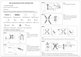
ASSEMBLE THE FIXED WHEELS (FIG. 1 & 2)
Parts Needed:
• Back Corner Brackets (2)
• Wheels (2)
• M6x50 Hex Bolts (2)
• Wheel Spacers (2)
• M6 Lock Nuts (2)
• 10mm Wrench (1)
1. From the outside of the corner bracket (Fig. 1 - 1), insert a M6x50 hex bolt
through the wheel bracket, the wheel and the wheel spacer (Fig. 2 - 1). At-
tach the M6 lock nut from the inside of the bracket and tighten with a 10mm
wrench.
NOTE: Do not overtighten the nut, as this could pull the screw head against
the mounting bracket and cause the bracket to deform, impeding the wheel’s
function.
2. Repeat for the other back corner bracket.
ASSEMBLE THE SUPPORT FEET (FIG. 3 & 4)
Parts Needed:
• Front Corner Brackets (2)
• Support Feet (2)
• M10 Nuts (2)
• 17mm Wrench (1)
1. Take a front corner bracket (Fig. 3 - 1) and screw in the support foot (Fig.
3 - 2) from the bottom of the foot flange.
NOTE: Adjust the height of the rubber foot so that the foot’s bottom surface
is at the same height as the bottom of the fixed wheels. This will make the
base level when resting on the rubber feet and wheels.
2. Attach the M10 nut onto the rubber support foot. Check that the foot is
set at a suitable height and tighten the M10 nut against the flange using a
17mm wrench.
3. Repeat for the other front corner bracket.
7
ASSEMBLY & ADJUSTMENTS
TOOLS NEEDED (NOT INCLUDED):
• Tape Measure • 13mm (1/2 in.) Wrench or Socket
• 10mm (3/8 in.) Wrench or Socket • 17mm (5/8 in.) Wrench or Socket
WARNING! Do not operate the mobile base until it has been fully assembled according to the instructions.
Follow all warnings to reduce the risk of personal injury or machine damage.
Fig. 1
Fig. 2
Fig. 3
Fig. 4
1
1
12

8
ASSEMBLE THE SWIVEL PLATES (FIG. 5)
Parts Needed:
• Swivel Plates (2)
• M6x70 Hex Bolts (2)
• M6 Lock Nuts (2)
• 10 mm Wrench (1)
1. From the outside of the front corner bracket, insert the M6x70 hex bolt
through the lower hole of the caster flange (Fig. 5 - 1) and the swivel plate
(Fig. 5 - 2). Secure with an M6 lock nut from the other side of the caster
flange and tighten it using a 10mm wrench.
2. Check that the swivel plate is able to swivel upwards, but not downwards.
ASSEMBLE THE SWIVEL CASTERS (FIG. 6)
Parts Needed:
• Two swivel casters (8)
• Two caster lock washers (S6)
• Two M10 nuts (S4)
• 17mm wrench
1. From the bottom of the swivel plate, insert the swivel caster (Fig. 6 - 1)
through the swivel plate (Fig. 6 - 2) and the caster lock washer. Secure with
an M10 flange nut and tighten the nut using a 17mm wrench.
ASSEMBLE THE FOOT LEVERS (FIG. 7, 8, & 9)
Parts Needed:
• Foot Levers (2)
• M8x70 Hex Bolts (2)
• Lever Spacers (4)
• Lever Lock Washers (2)
• M8 Nuts (2)
• 13mm Wrench (1)
1. From the outside of the front corner bracket, insert the M8x70 hex bolt
through the upper hole of the caster flange (Fig. 7 - 1), a lever spacer, the
foot lever (Fig. 8 - 1), another lever spacer, and finally through the upper
hole on the inside of the caster flange. Attach the lever lock washer and M10
flanged nut from the inside of the caster flange and tighten the nut using a
13mm wrench.
2. Test the mechanism of the foot levers. When the foot lever is depressed,
the base will be mobile, resting on the caster wheel. When the foot lever is
raised, the caster wheel will be raised with the rubber foot resting on the
ground and the base will be static (Fig. 9).
ASSEMBLY & ADJUSTMENTS
Fig. 5
Fig. 6
Fig. 7
Fig. 8
2
1
1
2
Fig. 9
1
1

9
ASSEMBLE THE RAILS (FIG. 10, 11, 12, & 13)
Parts Needed:
• Short Side Rails (4)
• Long Side Rails (4)
• M6x12 Hex Bolts (24)
• M6 Flanged Nuts (24)
• 10mm Wrench (1)
TIP: Start by loosely fastening all bolts and nuts in this step for ease of as-
sembly. Once all bolts and nuts have been assembled, securely tighten all
fasteners for a stable base.
1. Carefully measure the footprint of the machine that will be placed onto the
mobile base. Add about 1 inch to the dimension to allow clearance for the
fasteners. Note that the distance between the holes on the rail is 1 inch, so
that rails can be adjusted in 1-inch increments.
NOTE: If it will be difficult to to move your machine from the floor onto the
mobile base, raise it off the floor with four 2x4 blocks and assemble the base
around your machine.
2. Refer to the exploded view. Position the corners and rails in the desired
dimensions and arrangement. To maximize stability, position the side rails
into the corner brackets as far as is practical.
3. Assemble the side rails to the corner brackets. Each rail must be secured
to its corner bracket using two M6x12 hex bolts and two M6 flanged nuts.
Insert the M6x12 hex bolt from the outside and tighten M6 nut from the
inside using a 10mm wrench. The fasteners do not need to be in adjacent
holes and are more stable the further apart they are able to be configured
(Fig. 10).
4. Assemble the side rails together. The short rails will slide into the long
rails. Each rail must be secured to its mating rail using two M6x12 hex bolts
and two M6 flanged nuts. Position the fasteners as far apart as possible to
maximize stability. Insert the M6x12 hex bolt from the outside and tighten
M6 nut from the inside using a 10mm wrench (Fig. 11).
5. Check that all connections are secure. Lift up the foot levers to put the
base in its static configuration, and check that it is level. If needed, you may
need to adjust the rubber support foot height, see “Assemble the Support
Feet” section.
ASSEMBLY & ADJUSTMENTS
Fig. 10
Fig. 11
Fig. 12
Fig. 13

10
Mobile Configuration: Foot levers depressed, mobile
base resting on the swivel casters.
Static Configuration: Foot levers raised, mobile base
resting on the rubber feet.
OPERATING THE MOBILE BASE (FIG. 14 & 15)
1. Place the fully assembled mobile base on a level surface.
2. Carefully plan the orientation of the machine onto the mobile base. When the mobile base is in the rmobile con-
figuration, the foot lever side will be lifted 1.2 inches (30mm) higher that the fixed wheel side. To minimize the risk
of the machine being tipped over, the heaviest weight should be positioned at the foot lever side.
3. Securely bolt the machine onto the mobile base using the mounting holes on the surface of each corner piece.
4. The total weight being placed on the mobile base must not exceed the maximum weight capacity of 500 lbs.
5. Unplug any electrical tools before moving or repositioning the machine.
6. To move the machine, step down on the two foot levers of the mobile base to raise the base into mobile configu-
ration. When moving, always push on the base but not the machine itself to minimize of risk of tipping the machine
over. To stabilize the machine, lift up the foot levers to lower the base into the static configuration.
OPERATION
7. Test the stability in both the mobile configuration (on the casters) and the static configuration (on the rubber
feet). Use extra caution when raising top heavy machines such as drill presses and band saws as they have a higher
chance of being tipped over.
8. Never use your machine while the base is in the mobile configuration. Always lower the machine into the static
configuration and check that it is stable before operation.
9. Always test your setup for stability and safety after repositioning.
Fig. 14 Fig. 15

11
EXPLODED VIEW & PARTS LIST
NO. PART NO. DESCRIPTION QTY.
1 MB500-001 Corner (Back-Left) 1
2 MB500-002 Corner (Back-Right) 1
3 MB500-003 Wheel, 3” 2
4 MB500-004 Corner (Front-Left) 1
5 MB500-005 Corner (Front-Right) 1
6 MB500-006 Support Foot 2
7 MB500-007 Swivel Plate 2
8 MB500-008 Swivel Caster 2
9 MB500-009 Foot Lever 2
10 MB500-011 Short Side Rail 4
11 MB500-010 Long Side Rail 4
NO. PART NO. DESCRIPTION QTY.
S1 MB500-101 M6x50 Hex Screw 2
S2 MB500-102 Wheel Spacer 2
S3 MB500-103 M6 Lock Nut 4
S4 MB500-104 M10 Nut 4
S5 MB500-105 M6x70 Hex Screw 2
S6 MB500-106 Caster Lock Washer 2
S7 MB500-107 M8x70 Hex Screw 2
S8 MB500-108 Lever Spacer 4
S9 MB500-109 Lever Lock Washer 2
S10 MB500-110 M8 Nut 2
S11 MB500-111 M6x12 Hex Screw 24
S12 MB500-112 M6 Flanged Nuts 24
Components: Hardware:
NOTE: Not all parts may be available for purchase.

12
WARRANTY STATEMENT
WEN Products is committed to building tools that are dependable for years. Our warranties are consistent with this
commitment and our dedication to qualit
y.
LIMITED WARRANTY OF WEN PRODUCTS FOR HOME USE
GRE
AT LAKES TECHNOLOGIES, LLC (“Seller”) warrants to the original purchaser only, that all WEN
consumer
power tools will be free from defects in material or workmanship during personal use for a period of two (2) years
used
for professional or commercial use. Purchaser has 30 days from the date of purchase to report missing or
damaged parts.
SELLER’S
SOLE OBLIGATION AND YOUR EXCLUSIVE REMEDY under this Limited Warranty and, to the extent per-
mitted
by law, any warranty or condition implied by law, shall be the replacement of parts, without charge, which a
re
defective
in material or workmanship and which have not been subjected to misuse, alteration, careless handling,
misrepai
r, abuse, neglect, normal wear and tear,
improper maintenance, or other conditions adversely affecting the
Product
or the component of the Product, whether by accident or intentionally, by persons other than Seller. To
make
a claim under this Limited Warranty, you must make sure to keep a copy of your proof of purchase that
clearly
-
dor
of Great Lakes Technologies, LLC. Purchasing through third party vendors, including but not limited to garage
sales,
pawn shops, resale shops, or any other secondhand merchant, voids the warranty included with this
product.
Contact [email protected] or 1-800-232-1195 with the following information to make arrangements:
your
shipping address, phone number, serial number, required part numbers, and proof of purchase. Damaged
or
defective parts and products may need to be sent to WEN before the replacements can be shipped out.
-
turning
a product for warranty service, the shipping charges must be prepaid by the purchaser. The product
must
be
shipped in its original container (or an equivalent), properly packed to withstand the hazards of shipment. The
product
must be fully insured with a copy of the proof of purchase enclosed. There must also be a description of
the
will be returned and shipped back to the pur
chaser at no charge for addresses within the contiguous United States.
THIS
LIMITED WARRANTY DOES NOT APPLY TO ITEMS THAT WEAR OUT FROM REGULAR USAGE OVER TIME,
INCLUDING
BELTS, BRUSHES, BLADES, BATTERIES, ETC. ANY IMPLIED WARRANTIES SHALL BE LIMITED IN
DUR
ATION TO TWO (2) YEARS FROM DATE OF PURCHASE. SOME STATES IN THE U.S. AND SOME CANADIAN
PROVINCES
DO NOT ALLOW LIMITATIONS ON HOW LONG AN IMPLIED WARRANTY LASTS, SO THE ABOVE LIMI-
TAT
ION MAY NOT APPLY TO YOU.
IN
NO EVENT SHALL SELLER BE LIABLE FOR ANY INCIDENTAL OR CONSEQUENTIAL DAMAGES (INCLUDING
BUT
NOT LIMITED TO LIABILITY FOR LOSS OF PROFITS) ARISING FROM THE SALE OR USE OF THIS PRODUCT.
SOME ST
ATES IN THE U.S. AND SOME CANADIAN PROVINCES DO NOT ALLOW THE EXCLUSION OR LIMITAT
ION
OF
INCIDENTAL OR CONSEQUENTIAL DAMAGES, SO THE ABOVE LIMITATION OR EXCLUSION MAY NOT APPLY
TO YOU.
THIS
LIMITED WARRANTY GIVES YOU SPECIFIC LEGAL RIGHTS, AND YOU MAY ALSO HAVE OTHER RIGHTS
WHICH
VARY FROM STATE TO STATE IN THE U.S., PROVINCE TO PROVINCE IN CANADA AND FROM COUNTRY
TO COUNT
RY.
THIS
LIMITED WARRANTY APPLIES ONLY TO ITEMS SOLD WITHIN THE UNITED STATES OF AMERICA, CANA-
DA
AND THE COMMONWEALTH OF PUERTO RICO. FOR WARRANTY COVERAGE WITHIN OTHER
COUNTRIES,
CONT
ACT THE WEN CUSTOMER SUPPORT LINE. FOR WARRANTY PARTS OR PRODUCTS REPAIRED UNDER
W
ARRANTY SHIPPING TO ADDRESSES OUTSIDE OF THE CONTIGUOUS UNITED STATES, ADDITIONAL
SHIPPING
CHARGES MAY APPLY.
V. 2021.05.20
/