Page is loading ...

Rails shown suit tray 42104B
Tools Required
13mm Spanner, Phillips Screwdriver, Electric Drill,
5.5mm Drill Bit, Drop Saw or Hack Saw, File.
Care Instruction
Clean alloy tray prior to tting the Pioneer Rail Kit.
7
61
8
9
10
3
5
4
11
2
Rhino-Rack
3 Pike Street, Rydalmere, Document No: R035
NSW 2116, Australia. Prepared By: Nigel Greig Issue No: 06
(Ph) (02) 9638 4744 Authorised By: Chris Murty Issue Date: 24/07/2015
(Fax) (02) 9638 4822
These instructions remain the property of Rhinorack Australia Pty Ltd and may not be used or changed for any other purpose than intended.
Page 1 of 7
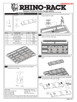
Rhino Pioneer Side Rail Kit
(43140B - 43149B & 43200B)
Place these instructions in the vehicle’s glove box after installation is complete.
Important: Please read these instructions carefully prior to installation.
Please refer to your tting instruction to ensure that the alloy tray is installed correctly.
Check the contents of this kit before commencing tment and report any discrepancies.
CONTROLLED

Quantity
Item Component Name Part No. 43140B 43141B 43142B 43143B 43144B 43145B 43146B 43147B 43148B 43149B 43200B
1 Rail Extrusion - 2 2 2 2 2 2 2 2 2 2 2
2End Moulding LH M51522222222222
3End Moulding LH Cover M516 2 2 2 2 2 2 2 2 2 2 2
4End Moulding RH M51722222222222
5End Moulding RH Cover M518 2 2 2 2 2 2 2 2 2 2 2
6 Rail Support M514 6 10 12 4 8 8 4 2 8 4 6
7 Phillips Screw B176 8 8 8 8 8 8 8 8 8 4 4
8 M8 x 20mm Hex Bolt B020 10 14 16 8 12 12 8 6 12 8 10
9M8 Spring Washer W019 10 14 16 8 12 12 8 6 12 8 10
10 M8 x 30mm Flat Washer C949 10 14 16 8 12 12 8 6 12 8 10
11 M8 Channel Nut N003 10 14 16 8 12 12 8 6 12 8 10
12 Fitting Instructions R035 1 1 1 1 1 1 1 1 1 1 1
Suits Trays 42100B
42101B
42104B
42107B
42105B 42106B 42102B
42103B
42108B 42109B
42110B
42111B
42112B 42113B 42114B 42115B
Rail Length (mm) 900 1500 2100 372 1300 1200 700 300 1350 600 850
Page 2 of 7
Rhino Pioneer Side Rail Kit

1Fit Hardware to Mouldings
Loosely t hardware to all the mouldings as shown. Be sure to set the bolts so they locate half way through the
channel nut (see image A below).
M8 x 20 Hex Bolt
M8 Spring Washer
M8 x 30 Flat Washer
M8 Channel Nut
M8 x 20 Hex Bolt
M8 Spring Washer
M8 x 30 Flat Washer
M8 Channel Nut
End Moulding
Rail
Support
Make sure bolt locates half
way through channel nut.
A
2Fit End Moulding to Rail
Fit one of the end mouldings to the rail extrusion as shown and fasten in place with screw provided in kit.
Rail Extrusion
Screw
End Moulding
Page 3 of 7
Rhino Pioneer Side Rail Kit

Fit Rail Support Mouldings to Rail
Slide the rail supports onto the rail extrusion as shown. Refer table below for the correct number of supports to suit
your tray. Proceed to t the end moulding and fasten in place with screw. Slide all the rail supports to one end of the
rail.
Platform Tray No. Supports
per rail
42100B 3
42101B 3
42102B 4
42103B 4
42104B 5
42105B 6
42106B 2
42107B 5
42108B 4
42109B 2
42110B 2
42111B 2
42112B 1
42113B 4
42114B 2
42115B 3
3
Rail Extrusion
Rail Support
End
Moulding
Screw
Page 4 of 7
Rhino Pioneer Side Rail Kit

5Engage Side Supports
Lift the rail slightly and slide the rst rail support so that the channel nut locates over the slot in the front of the tray.
Lower the rail so the channel nut locates within the slot and slide the support all the way along the rail until it hits the
end moulding. Repeat operation for remaining rail supports.
4Insert First Channel Nut into Slot
Lower the rail assembly onto the tray so that the channel nut tted to the end moulding locates within the slot in the
front of the tray. Next slide the rail assembly onto the tray slightly so the nut engages in the channel.
Rail Assembly
Slot
FRONT
Page 5 of 7
Rhino Pioneer Side Rail Kit

8Fit End Moulding Covers
Insert the bottom corner of the cover rst, then snap the other end of the cover in place. Fasten the cover with the
screw provided in kit. Repeat for cover at other end of rail.
Insert this Corner First
Screw
6Engage End Moulding & Position Rail
Engage the end moulding in the same manner as before and position the rail on the tray as shown below with an
even spacing at either end.
= =
7Position Rail Supports
Position the rail supports as shown below, tighten all bolts on the rail with a 13mm spanner.
50mm 50mm
= = = =
9Repeat the process above to assemble and t the second side rail assembly.
Page 6 of 7
Rhino Pioneer Side Rail Kit

Fitment Options
FRONT FRONT
Page 7 of 7
Rhino Pioneer Side Rail Kit
/


