Page is loading ...

All content in this instruction is property of the Waterous Company. Instructions subject to change without notice.All content in this instruction is property of the Waterous Company. Instructions subject to change without notice.All content in this instruction is property of the Waterous Company. Instructions subject to change without notice.
Overhaul Instructions
CZ Series Fire Pumps Section
4213
Form No.
F-1031
Issue Date Rev. Date
12/08/0910/92
Waterous Company 125 Hardman Avenue South, South St. Paul, Minnesota 55075 USA (651) 450-5000
Instructions subject to change without notice.
Table of Contents
Introduction 1. . . . . . . . . . . . . . . . . . . . . . . . . . . . . . .
General Overhaul Information 1. . . . . . . . . . . . .
Tools and Equipment 1. . . . . . . . . . . . . . . . . . . . . .
Preliminary Testing 1. . . . . . . . . . . . . . . . . . . . . . . .
Cleaning 1. . . . . . . . . . . . . . . . . . . . . . . . . . . . . . . . .
Pump Bodies and Impellers 1. . . . . . . . . . . . . . . . .
Bearings, Gaskets, Seals and O-rings 1. . . . . . .
Impeller Shafts 1. . . . . . . . . . . . . . . . . . . . . . . . . . . .
Installing Ball Bearings 2. . . . . . . . . . . . . . . . . . . . .
Installing Body Gaskets 2. . . . . . . . . . . . . . . . . . . .
Disassembly 2. . . . . . . . . . . . . . . . . . . . . . . . . . . . .
Inspection and Repair 4. . . . . . . . . . . . . . . . . . . .
Impellers 3. . . . . . . . . . . . . . . . . . . . . . . . . . . . . . . . .
Installing Undersize Wear Rings 3. . . . . . . . . . . . .
Impeller Shaft 4. . . . . . . . . . . . . . . . . . . . . . . . . . . . .
Oil Seal Sleeve 4. . . . . . . . . . . . . . . . . . . . . . . . . . .
Volute Body and Intake Adapter 4. . . . . . . . . . . . .
Reassembly 4. . . . . . . . . . . . . . . . . . . . . . . . . . . . .
Final Assembly 6. . . . . . . . . . . . . . . . . . . . . . . . . .
Testing 6. . . . . . . . . . . . . . . . . . . . . . . . . . . . . . . . . .
Hydrostatic Testing 6. . . . . . . . . . . . . . . . . . . . . . . .
Operational Testing 6. . . . . . . . . . . . . . . . . . . . . . . .
Illustrations
1. Mechanical Seal Lubrication Application 5. . . . .
CZ Series
Overhaul

Page 1 of 7F-1031, Section 4213
Introduction
This instruction contains the information needed to overhaul and repair
Waterous CZ and CZU series centrifugal fire pumps. Note that these
instructions are for CZU series fire pumps built prior to August, 2003.
The text uses reference numbers when discussing specific parts. These
numbers refer to the parts called out on the Service Parts List which is
supplied with the pump.
General Overhaul Information
Tools and Equipment
The following tools and equipment are needed to overhaul a pump:
1. Usual automotive mechanic's hand tools.
2. An arbor press for assembling or disassembling components.
3. An engine lathe for turning impeller hubs.
4. A suitable hoist and slings.
5. Torque capability up to 325 lb-ft.
While no special tools and equipment are required, a few special items
are illustrated or described so the mechanic can make them or they are
available from the apparatus manufacturer or the Waterous Company.
These special items are not absolutely necessary, but they will make the
mechanic's work much easier.
Preliminary Testing
Before disassembling a pump, test it thoroughly, if possible, and record
the results. A comparison of this test with periodic tests recommended in
form F-1031, Section 1000 can often reveal specific pump troubles.
Excessive speed, for instance, indicates that impellers and/or wear rings
are probably worn.
Cleaning
The continued satisfactory operation of a pump depends to a great ex‐
tent upon the cleanliness of its internal parts. Sand, dirt or other abrasive
material will wear bearings, gears and related parts. Before disassem‐
bling a pump for repairs, be sure to clean its exterior. Make sure the
working space, benches and tools are clean. Use only clean, lint-free
cloths to wipe off components. Before reassembling a pump or its com‐
ponents, be sure to clean them thoroughly.
Pump Bodies and Impellers
Flush out these components and related parts with clean water. Use a
stiff brush to remove loose scale, caked sediment, etc. Be sure to re‐
move all traces of old gaskets. Examine pump bodies, covers, adapters
and fittings for cracks, severe corrosion or other damage. Almost all
damage to these parts results from improper use or maintenance, or
from freezing. Replace defective parts.
Bearings, Gaskets, Seals and O-rings
Parts of this nature are frequently damaged during removal or disas‐
sembly. In addition, they sometimes deteriorate or lose their effective‐
ness because of age or misuse. Replacing these parts whenever over‐
hauling a pump is a good policy.
Impeller Shafts
Examine shaft for severe scratches, grooves or corrosion - especially
under packing or mechanical seals. If scratches are not severe, and are
not under packing and seals, clean them with a fine-cut file. Grooves are
usually permissible if they are not sharp or too deep. Even slight longitu‐
dinal scratches will cause leaks and should be removed.
End Yoke and Companion Flange Nuts
Do not reuse self-locking nuts. Apply lubrication to the threads before
removing. Apply anti-seize to the threads before installing a new self-
locking nut.

Page 2 of 7F-1031, Section 4213
Installing Ball Bearings
Most Waterous pumps are designed so that ball bearings fit tightly on
their shafts and have relatively loose fits in the bearing housings. When
mounting these bearings on shafts, always apply force to the inner races.
When bearings have a tight fit in the housings, and a heavy force is
necessary to install them, be sure to apply force only to the outer bearing
races. For either type of fit, applying force to the wrong bearing race may
damage the balls and race.
Installing Body Gaskets
To provide added sealing for gaskets between body halves, or between
bodies and intake adapters, coat both sides of these gaskets with a
suitable sealant. A compound such as Permatex Super 300 is recom‐
mended for this application. Be sure all traces of previous gaskets and
sealant are removed before installing new gaskets.
Disassembl
y
NOTE: The wear rings (S3) in the volute body (B1) and intake adapt‐
ers (B2) cannot be removed without ruining them. They should only
be removed if new wear rings are required.
1. (CZU Pumps Only) Remove screws (B14) that attach discharge
adapter (B13) to volute body (B1). Remove O-ring (B17) from dis‐
charge adapter and discard.
2. Remove screws (B5) that attach intake adapter (B2) to volute body.
Remove O-ring (B9) from the intake adapter and discard.
3. Remove cotter pin (S10 or S17) impeller nut (S4) and impeller wash‐
er (S7).
4. Remove impeller (S1) from impeller shaft (S2). Tapping the impeller
lightly with a soft hammer may be necessary to free it from the impel‐
ler shaft so it can be removed. There are 5/16-18 NC tapped holes
in the impeller to allow use of a puller if necessary.
5. Remove key (S14) from the impeller shaft.
6. Remove spring from the mechanical seal (S9).
7. Apply a light coating of oil to the portion of the impeller shaft the
mechanical seal is on. Grasp the seal by hand and try to remove it
with a combined pulling and twisting motion. If it is stuck to the shaft
and will not come off, it will come off when the impeller shaft and
bearing housing are separated from the volute body.
NOTE: If only the mechanical seal is to be serviced, proceed
through steps 1 thru 13 and then tap out the mechanical seal sta‐
tionary seal ring in the volute body being sure not to damage the oil
seal (S12) in the volute body.
8. Stand the pump in a vertical position, resting it on the face of the
volute body.
9. Remove screws (B5) fastening the bearing housing (B3) to the volute
body. Tap the bearing housing lightly with a soft hammer to free it
from the volute body.
10. Rig a sling to the end yoke that is attached to the impeller shaft. With
a hoist, lift the shaft and housing from the volute body. The impeller
shaft will probably adhere to the bellows of the mechanical seal and
it will be necessary to jiggle the shaft as it is being removed. If the
volute body lifts with the shaft, due to adherence of the bellows to the
shaft, tap on the volute body with a soft hammer.
11. Remove the O-ring (B6) from the groove in the face of the bearing
housing and discard.
12. With the shaft and bearing housing detached from the hoist, remove
cotter pin (S10), shaft nut (S8) and flat washer (S13) that attach the
yoke to the impeller shaft.
13. Remove the end yoke from the impeller shaft.
14. Slide the bearing housing off the ball bearings (S15 & S16) on the
impeller shaft. Remove the breather (B4), snubber (B12), pipe plugs
(B8) and oil seal (S11) from the bearing housing.
15. Position the impeller shaft assembly in a vertical position in an arbor
press with the spline end of the shaft up and the impeller end of the
inner race of the bearing (S15) supported by the table of the press.
Press the shaft out of the bearings (S15 & S16), bearing spacer (S5)
and oil seal sleeve (S6).
CAUTION
When the shaft is free of bearing (S15) it will fall free. Blocking
should be provided under the shaft.

Page 3 of 7F-1031, Section 4213
16. With a brass drift pin, tap the mechanical seal ring out of the volute
body.
17. Remove the oil seal (S12) and pipe plug (B8, B15 or B19)) from the
volute body.
18. If the wear rings (S3) in the volute body and the intake adapter are to
be replaced they must be driven out of the body or adapter by using
a chisel end punch. When they have moved outward approximately
1/8 to 3/16”, it may then be possible to pry them out by using a pry
bar behind the wear ring.
Ins
p
ection and Re
p
air
Impeller
Check wear rings and impeller hubs for deep grooves or scratches.
Spiral grooves or grooves parallel to the impeller shaft increase leakage.
Inspect for excessive wear ring clearance. Diametric clearances in ex‐
cess of those shown in the table below may warrant wear ring replace‐
ment. Original factory clearance is shown in the table. The diametric
clearance should be determined by averaging the results of four mea‐
surements taken at 90 degree increments as follows:
Clean and remove small burrs or other protrusions from the wear ring
inner diameters and the impeller hub O.D. and I.D. Position each wear
ring on the impeller hub on which it was used. Hold the wear ring firmly
against one side of the hub and measure total clearance on the opposite
side, using a feeler gauge. Do not bottom the wear ring against the bot‐
tom of the groove in the impeller.
Installing Undersize Wear Rings
Replacement wear rings are available as follows:
•0.025 in. undersize
•0.050 in. undersize
•0.075 in. undersize
If inspection shows that the wear ring clearances are excessive or the
impeller hubs are scored or grooved, turn the impeller hub on a lathe to
an acceptable dimension. Table 1. shows the original hub dimensions for
each impeller and the rework dimensions for each degree of undersize.
NOTE: Wear rings may be removed by crisscrossing two pry bars
under opposite sides of the wear ring. Pry up the wear ring by ap‐
plying equal pressure to both pry bars.
Table 1. Impeller and Wear Ring Repair Dimensions
Pump Model Impeller No. Impeller Bore Original Hub
Dia.
Original Wear
Ring No.
Factory Wear
Ring
Clearance
(Diametric)
Rework
Impeller if
Wear Ring
Clearance
Exceeds:
(Diametric)
Reworked
Hub Dia.
New Wear
Ring No.
CZ 81650
82204 Keyed 6.030/6.028 62816 .019/.023 0.027
6.005/6.003
5.980/5.978
5.955/5.953
62816-25
62816-50
62816-75

Page 4 of 7F-1031, Section 4213
Keep the hub diameters within 0.015 in. TIR of the impeller shaft bore. If
the impeller hubs do not clean up at first undersize dimension, turn the
hub down to the next degree of undersize. Replace the impeller if the
hubs do not clean up at the last undersize dimension.
Before pressing new wear rings in place, remove all corrosion from body
and head counterbores and apply a generous amount of lubricate or
similar lubricant to the outer ring surfaces. With a suitable arbor, carefully
press the rings into the body and head counterbores. Make sure the
rings are seated firmly against the counterbore shoulders.
Impeller Shaft
Examine shaft for signs of severe scratches, grooves or corrosion. If
scratches are not severe, and are not under seals, they can be ignored.
Check for cracks, pitting, twisted splines or damaged keyway.
Scratches in the area of the bellows of the mechanical seal can possibly
be removed by spinning the shaft in a lathe and polishing with a fine
emery cloth. The journal for the oil seal may be similarly cleaned, howev‐
er, spiral type polishing may lead to oil leaks.
Oil Seal Sleeve
Check for wear and scratches where the seal contacts the sleeve. The
journal may be polished with a fine emery cloth, however; any polishing
that leaves a spiral pattern may lead to an oil leak. If a groove has been
worn in the sleeve, it can be reused by turning it end for end. If question‐
able, replace the sleeve.
Volute Body and Intake Adapter
Examine these for cracks, severe corrosion or other damage. Almost all
damage to these parts results from improper use or maintenance, or
from freezing. Replace defective parts.
Clean out drainage hole in volute body, located between the seat for the
oil seal and stationary seal ring of the mechanical seal.
Reassembl
y
NOTE: These instructions are written based on installation of new
wear rings, either standard size or under size. The wear ring hubs
on the impeller are sized to suit.
1. Slide both wear rings (S3) onto the impeller (S1) with the tapered
(concave) end towards the impeller. With the inner wear ring over‐
hanging the impeller by 1/4 inch there should be radial shake be‐
tween the wear ring and impeller. Similar radial shake should exist
between the outer wear ring and impeller with the wear ring over‐
hanging the impeller by 1/8 inch. Do not bottom the wear rings with
the impeller when checking for radial shake.
2. Inspect the bore for the wear ring in the intake adapter and volute
body for any raised burrs or nicks that may have occurred when
removing the old wear rings. Remove any burrs or nicks before in‐
stalling new wear rings.
3. Position the intake adapter (B2) on a bench with the bore for the
wear ring facing up. Position the wear ring in the bore with the
square end down. Apply Loctite 609 to assist in wear ring retention.
With a soft hammer, begin seating the ring squarely into the bore and
then drive it down by hitting it evenly from side to side until it bottoms
against the shoulder at the bottom of the bore.
4. Install the wear ring in the volute body (B1) the same way as that
installed in the intake adapter.
5. Before installing an oil seal (S12) in a housing, apply a thin coat of
sealant to housing oil seal seat. (Waterous recommends Loctite Ultra
Blue RTV Silicon Sealant to Permatex Super 300). Be sure that the
seal, shaft and housing are clean. Always install a seal with the seal
lip facing in. Apply force to the outer edge of the seal and press in
evenly.
6. Support bearing (S15) on the face of the inner race and press the
impeller shaft (S2) yoke spline end first thru the bearing until the
shoulder on the shaft is tight against the bearing.
7. Slide spacer (S5) on the shaft, against the bearing (S15). Press
bearing (S16) onto shaft, tight up against the spacer. Press oil seal
sleeve (S6) onto the shaft, tight up against bearing (S16).
8. Position the volute body on the bench, resting it on the face the
intake adapter bolts to.

Page 5 of 7F-1031, Section 4213
9. Take the previously assembled shaft and temporarily install the end
yoke and secure it with the shaft nut (S8). Finger tighten only.
10. Secure a sling to the end yoke and lift the shaft until it hangs vertical‐
ly above the volute body.
11. Align the shaft with the oil seal in the volute body and slowly lower
the shaft through the oil seal in the body until the outer race of bear‐
ing (S15) seats against the hub on the body.
CAUTION
As the journal on the shaft for the oil seal begins to enter the oil
seal, make sure the seal lip does not turn under or the garter
spring in the seal does not pop out of position.
12. Remove the shaft nut and the end yoke from the shaft.
13. Install the oil seal (S11) in the end of the bearing housing with the
seal lip towards the inside of the housing.
14. Apply a light film of grease in the groove in the face of the bearing
housing. Install O-ring (B6) in this groove.
15. Position the bearing housing over the shaft, rotating it to its correct
relation to the volute body. Slide it down over bearings (S15) and
(S16) until it seats against the volute body. Line up holes and install
screws and lock washers (B5) and (B7), torque to 45 Lb.Ft.
16. Reassembly of the bearing housing and impeller shaft to the volute
body should restore alignment to each other. To check the alignment,
attach an indicator to the impeller shaft and rotate the shaft and
indicate the bore in the volute body. The runout should be within .005
T.I.R. If the runout exceeds this, the following should be checked:
17. Raised burr or nick on faces of the bolted joint between the bearing
housing and volute body.
18. Foreign material caught between the joint.
19. O-ring out of position and pinched between the joint.
20. Temporarily install the impeller and rotate the impeller shaft. The
impeller should rotate without contact with the wear ring in the volute
body. Remove the impeller.
CAUTION
The mechanical seal primary and stationary rings are made of
brittle material. The material can be cracked or chipped. Extra care
must be taken when handling these rings.
NOTE: If Waterous Mechanical Seal Lubricant part no. 52608 is
not available, P80 rubber lubricant, straight dish soap or glycer‐
in may be substituted.
21. Apply a light coating of seal lubricant to the O-ring in the stationary
seal ring of the mechanical seal (S9).
Note: To protect the rubber bellows of the mechanical seal,
place a piece of masking tape over the keyway on the impeller
shaft, making sure that the tape is able to be removed after
bellows has passed over the keyway.
22. Slip the seal ring over the end of the impeller shaft, with the finish
lapped face of the seal ring facing up (the opposite side of a new
seal ring has a mark on it). Slide it along the shaft and push it into
and seat it in the bore in the volute body. If it can not be pushed in by
hand it may be tapped into place by use of a block of wood between
the ring and a hammer.
23. Wipe the face of the previously installed stationary seal ring of the
mechanical seal with a clean lint free cloth or tissue paper.
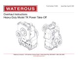
24. Coat the inside seal bellow with 3M 1357 neoprene adhesive and let
sit for 5 minutes or until it becomes tacky. Wipe the face of the car‐
bon ring with a lint free cloth or tissue paper. Apply enough seal
lubricant (P80) on the shaft for the seal to ride on. Slide the seal onto
the shaft until the carbon ring contacts the stationary seal ring.
IL1024
Figure 1. Mechanical Seal Lubricant Application
Coat inside of seal bellow with
3M 1357 neoprene adhesive.
If lubricant should get on face of seal ring, wipe it
clean with soft cloth.
Coat shaft area where seal
bellow must slide over
to seat with seal lubricant (P80).

Page 6 of 7F-1031, Section 4213
25. Install the spring over the seal assembly
26. Install key (S14) in the impeller shaft and then install the impeller,
plain washer (S7) and impeller nut (S4) and snug up the nut. Rotate
the impeller to assure seating of the mechanical seal spring into the
counterbore on the backside of the impeller. If the spring is not prop‐
erly seated it will snap into place when the impeller is rotated.
27. Tighten impeller nut and line up slot in the nut with the hole in the
shaft. Install and secure cotter pin (S10 or S17).
28. Grease O-ring (B9) and install on the intake adapter.
29. Position the intake adapter to the volute body. Line up holes and tap
the adapter down into position. Install screws and lockwashers (B5)
and (B7). Tighten until the surface of the adapter meets the surface
of the volute body. Rotate the impeller shaft. Make sure the wear
rings and the impeller are not rubbing against each other.
30. If the impeller turns freely, tighten screws evenly from side to side.
Torque to 45 lb.ft.
31. If the impeller rubs against the wear rings, remove the adapter and
determine the cause. The following can cause rubbing:
a) Raised burr or nick on either the hub of the impeller or on the
wear ring.
b) Wear ring cocked when installed and is deformed sufficiently
to rub on the impeller.
c) Impeller hub was not reworked to correct size for use with new
undersize wear ring.
32. After correcting the problem of rubbing between the impeller and
wear rings, reinstall the intake adapter.
33. (CZU Pumps Only) Grease O-ring (B17) and install on the dis‐
charge adapter (B13). Position discharge adapter to volute body.
Install screws (B14).
34. Install pipe plug (B8, B15 or B19) in the volute body.
35. Install the two pipe plugs (B8) in the bearing housing. Install the
snubber (B12) in the upper hole in the housing and then the breather
(B4) into the snubber.
36. Place the end yoke on the impeller shaft. Install flat washer (S13)
and shaft nut (S8). Tighten nut. Anti-seize should be applied to the
threads before installing a self-locking nut. Do not reuse self-locking
nuts. Torque to 275-325 lb-ft.
Final Assembly
To complete final assembly, perform the following:
1. Connect the intake and discharge piping.
2. Connect the cooling and drain lines, electrical wiring and similar
equipment to the pump and accessories.
3. Remove filler plug or breather on the bearing housing, and pour fluid
through the opening. Fill to bottom thread of oil level hole. Do not
overfill. Use non-detergent SAE 30 oil.

Page 7 of 7F-1031, Section 4213
Testing
Before a pump can be returned to service, it is advisable to give the pump a hydrostatic and operational tests to check it for leaks and to make sure the
pump operates properly.
Hydrostatic Testing
1. Connect the pump to a hydrant or other pressurized water supply.
2. Close all drain lines and open the discharge and priming valves.
3. Open hydrant until the water runs out through the discharge valves
and discharge pipe in priming pump (if used).
4. Close all valves. Be sure to evacuate all air from the pump.
5. Check for leaks with a portable light. If leaks are discovered, tighten
connections or attaching parts as necessary. Repeat until all leaks
are eliminated.
NOTE: If a mechanical seal is used, the seal may leak under hydro‐
static pressure; however, it should stop leaking after the seal
faces are run in during operational testing.
6. Shut hydrant valve after all leaks are eliminated.
7. Drain pump completely and disconnect intake hose.
Operational Testing
1. Operate the pump at its maximum intended service pressure. (Refer
to NFPA 1911).
2. Check for leaks with a portable light. If leaks are discovered, stop the
pump and tighten connections or tighten attaching parts as neces‐
sary. Repeat until all leaks are eliminated.
3. Check for unusual noises, oil leaks, overheated bearings, etc. while
the pump is running. If anything unusual is discovered, stop the
pump immediately and determine the cause of the problem.
/