Page is loading ...

APOGEE INSTRUMENTS, INC. | 721 WEST 1800 NORTH, LOGAN, UTAH 84321, USA
TEL: (435) 792-4700 | FAX: (435) 787-8268 | WEB: APOGEEINSTRUMENTS.COM
Copyright © 2022 Apogee Instruments, Inc.
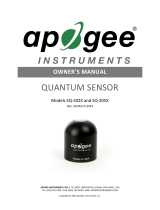
OWNER’S MANUAL
EPAR SENSOR
Model SQ-617
Rev: 30-Aug-2022

TABLE OF CONTENTS
Owner’s Manual ............................................................................................................................................................ 1
Certificates of Compliance ..................................................................................................................................... 3
Introduction ........................................................................................................................................................... 5
Sensor Models ....................................................................................................................................................... 7
Specifications ......................................................................................................................................................... 7
Deployment and Installation ............................................................................................................................... 11
Cable Connectors ................................................................................................................................................. 11
Operation and Measurement .............................................................................................................................. 13
Maintenance and Recalibration .......................................................................................................................... 19
Troubleshooting and Customer Support ............................................................................................................. 20
Return and Warranty Policy ................................................................................................................................ 21

CERTIFICATE OF COMPLIANCE
EU Declaration of Conformity
This declaration of conformity is issued under the sole responsibility of the manufacturer:
Apogee Instruments, Inc.
721 W 1800 N
Logan, Utah 84321
USA
for the following product(s):
Models: SQ-617
Type: ePAR Sensor
The object of the declaration described above is in conformity with the relevant Union harmonization legislation:
2014/30/EU Electromagnetic Compatibility (EMC) Directive
2011/65/EU Restriction of Hazardous Substances (RoHS 2) Directive
2015/863/EU Amending Annex II to Directive 2011/65/EU (RoHS 3)
Standards referenced during compliance assessment:
EN 61326-1:2013 Electrical equipment for measurement, control, and laboratory use – EMC requirements
EN 63000:2018 Technical documentation for the assessment of electrical and electronic products with
respect to the restriction of hazardous substances
Please be advised that based on the information available to us from our raw material suppliers, the products
manufactured by us do not contain, as intentional additives, any of the restricted materials including lead (see
note below), mercury, cadmium, hexavalent chromium, polybrominated biphenyls (PBB), polybrominated
diphenyls (PBDE), bis (2-ethylhexyl) phthalate (DEHP), butyl benzyl phthalate (BBP), dibutyl phthalate (DBP), and
diisobutyl phthalate (DIBP). However, please note that articles containing greater than 0.1 % lead concentration
are RoHS 3 compliant using exemption 6c.
Further note that Apogee Instruments does not specifically run any analysis on our raw materials or end products
for the presence of these substances, but we rely on the information provided to us by our material suppliers.
Signed for and on behalf of:
Apogee Instruments, August 2022
Bruce Bugbee
President
Apogee Instruments, Inc.

CERTIFICATE OF COMPLIANCE
UK Declaration of Conformity
This declaration of conformity is issued under the sole responsibility of the manufacturer:
Apogee Instruments, Inc.
721 W 1800 N
Logan, Utah 84321
USA
for the following product(s):
Models: SQ-617
Type: ePAR Sensor
The object of the declaration described above is in conformity with the relevant UK Statutory Instruments and
their amendments:
2016 No. 1091 The Electromagnetic Compatibility Regulations 2016
2012 No. 3032 The Restriction of the Use of Certain Hazardous Substances in Electrical and Electronic
Equipment Regulations 2012
Standards referenced during compliance assessment:
BS EN 61326-1:2013 Electrical equipment for measurement, control, and laboratory use – EMC requirements
BS EN 63000:2018 Technical documentation for the assessment of electrical and electronic products with
respect to the restriction of hazardous substances
Please be advised that based on the information available to us from our raw material suppliers, the products
manufactured by us do not contain, as intentional additives, any of the restricted materials including lead (see
note below), mercury, cadmium, hexavalent chromium, polybrominated biphenyls (PBB), polybrominated
diphenyls (PBDE), bis (2-ethylhexyl) phthalate (DEHP), butyl benzyl phthalate (BBP), dibutyl phthalate (DBP), and
diisobutyl phthalate (DIBP). However, please note that articles containing greater than 0.1 % lead concentration
are RoHS 3 compliant using exemption 6c.
Further note that Apogee Instruments does not specifically run any analysis on our raw materials or end products
for the presence of these substances, but we rely on the information provided to us by our material suppliers.
Signed for and on behalf of:
Apogee Instruments, August 2022
Bruce Bugbee
President
Apogee Instruments, Inc.

INTRODUCTION
Radiation that drives photosynthesis is called photosynthetically active radiation (PAR) and, historically, is defined
as total radiation across a range of 400 to 700 nm. PAR is almost universally quantified as photosynthetic photon
flux density (PPFD) in units of micromoles per square meter per second (µmol m-2 s-1, equal to microEinsteins per
square meter per second) summed from 400 to 700 nm (total number of photons from 400 to 700 nm). However,
ultraviolet and far-red photons outside the defined PAR range of 400-700 nm can also contribute to
photosynthesis and influence plant responses (e.g., flowering).
Data from recent studies indicate that far-red photons synergistically interact with photons in the historically
defined PAR range of 400-700 nm to increase photochemical efficiency in leaves (Hogewoning et al., 2012;
Murakami et al., 2018; Zhen and van Iersel, 2017; Zhen et al., 2019). Measurements from whole plants and plant
canopies indicate adding far-red photons (using far-red LEDs with peaks near 735 nm and outputting photons
across a range of about 700-750 nm) to radiation sources outputting photons in the 400-700 nm range increases
canopy photosynthesis equal to the addition of the same number of photons in the 400-700 nm range for multiple
species, and C3 and C4 photosynthetic pathways, but far-red photons alone are photosynthetically inefficient and
result in minimal photosynthesis (Zhen and Bugbee, 2020a; Zhen and Bugbee, 2020b).
This research suggests that far-red photons drive canopy photosynthesis with similar efficiency as photons in the
traditional PAR range when they are acting synergistically with photons in the 400-700 nm range, meaning when
far-red photons are added to radiation sources outputting 400-700 nm photons. Thus, far-red photons need to be
included in the definition of PAR (Zhen et al., 2021).
Sensors that measure PPFD are often called quantum sensors due to the quantized nature of radiation. A quantum
refers to the minimum quantity of radiation, one photon, involved in physical interactions (e.g., absorption by
photosynthetic pigments). In other words, one photon is a single quantum of radiation. Sensors that function like
traditional quantum sensors but measure a wider range of wavelengths can be thought of as an ‘extended range’
quantum sensor.
Typical applications of traditional quantum sensors include incoming PPFD measurement over plant canopies in
outdoor environments or in greenhouses and growth chambers and reflected or under-canopy (transmitted) PPFD
measurement in the same environments. The extended photosynthetically active radiation (ePAR) sensor detailed
in this manual uses a detector that is sensitive to radiation from 383-757 nm ± 5 nm, which allows it to measure
photons from Far-red.
Apogee Instruments SQ-600 series ePAR sensors consist of a cast acrylic diffuser (filter), photodiode, and signal
processing circuitry mounted in an anodized aluminum housing. A cable to connect the sensor to a measurement
device is also included. SQ-600 series ePAR sensors are designed for continuous photon flux density measurements
in indoor or outdoor environments. The SQ-617 sensors output a digital signal using SDI-12 communication
protocol.
Hogewoning et al. 2012. Photosynthetic Quantum Yield Dynamics: From Photosystems to Leaves. The Plant Cell,
24: 1921–1935.

Murakami et al. 2018. A Mathematical Model of Photosynthetic Electron Transport in Response to the Light
Spectrum Based on Excitation Energy Distributed to Photosystems. Plant Cell Physiology. 59(8): 1643–1651.
Zhen and Van Iersel. 2017. Far-red light is needed for efficient photochemistry and photosynthesis. Journal of Plant
Physiology. 209: 115–122.
Zhen et al. 2019. Far-red light enhances photochemical efficiency in a wavelength-dependent manner. Physiologia
Plantarum. 167(1):21-33.
Zhen and Bugbee. 2020a. Far-red photons have equivalent efficiency to traditional photosynthetic photons:
Implications for redefining photosynthetically active radiation. Plant Cell and Environment. 2020; 1–14.
Zhen and Bugbee. 2020b. Substituting Far-Red for Traditionally Defined Photosynthetic Photons Results in Equal
Canopy Quantum Yield for CO2 Fixation and Increased Photon Capture During Long-Term Studies: Implications for
Re-Defining PAR. Frontiers in Plant Science. 11:1-14.
Zhen et al. 2021. Why Far-Red Photons Should Be Included in the Definition of Photosynthetic Photons and the
Measurement of Horticultural Fixture Efficacy. Frontiers in Plant Science. 12:1-4.

SENSOR MODELS
This manual covers the digital model SQ-617 ePAR SDI-12 Sensor (in bold below). Additional models are covered in
their respective manuals.
Model
Signal
SQ-610
Self-powered
SQ-612
0-2.5 V
SQ-614
4-20 mA
SQ-615
0-5 V
SQ-616
USB
SQ-617
SDI-12
SQ-618
Modbus
A sensor’s model number and serial number are located
on the bottom of the sensor. If the manufacturing date
of a specific sensor is required, please contact Apogee
Instruments with the serial number of the sensor.

SPECIFICATIONS
Calibration Traceability
Apogee Instruments SQ-600 series ePAR sensors are calibrated through side-by-side comparison to the mean of
four transfer standard sensors under a reference lamp. The transfer standard sensors are recalibrated with a
quartz halogen lamp traceable to the National Institute of Standards and Technology (NIST).
SQ-617-SS
Input Voltage
5.5 to 24 V DC
Current Draw
1.4 mA (quiescent), 1.8 mA (active)
Calibration Uncertainty
± 5 % (see Calibration Traceability below)
Measurement Range
0 to 4000 µmol m-2 s-1
Measurement
Repeatability
Less than 0.5 %
Long-term Drift
(Non-stability)
Less than 2 % per year
Non-linearity
Less than 1 % (up to 4000 µmol m-2 s-1)
Response Time
0.6 s, time for detector signal to reach 95 % following a step change; fastest data transmission
rate for SDI-12 circuitry is 1 s
Field of View
180°
Spectral Range
383 to 757 nm ± 5 nm (wavelengths where response is greater than 50 %; see Spectral
Response below)
Directional (Cosine)
Response
± 2 % at 45° zenith angle, ± 5 % at 75° zenith angle (see Directional Response below)
Azimuth Error
Less than 0.5 %
Tilt Error
Less than 0.5 %
Temperature Response
-0.11 ± 0.04 % per C
Uncertainty in Daily Total
Less than 5 %
Housing
Anodized aluminum body with acrylic diffuser
IP Rating
IP68
Operating Environment
-40 to 70 C; 0 to 100 % relative humidity; can be submerged in water up to depths of 30 m
Dimensions
30.5 mm diameter, 37 mm height
Mass (with 5 m of cable)
140 g
Cable
5 m of two conductor, shielded, twisted-pair wire; TPR jacket; pigtail lead wires; stainless steel
(316), M8 connector
Warranty
4 years against defects in materials and workmanship

Spectral Response
Mean spectral response measurements of
four replicate Apogee SQ-600 series ePAR
Sensors. Incremental spectral response
measurements were made at 10 nm
increments across a wavelength range of
370 to 800 nm in a monochromator with
an attached electric light source.
Measured spectral data from each
quantum sensor were refined and
normalized by comparing measured
spectral response of the
monochromator/electric light
combination to measured spectral
differences from a quantum sensor
reference.

Cosine Response
Directional, or cosine, response is defined as the
measurement error at a specific angle of radiation
incidence. Error for Apogee SQ-600 series ePAR Sensor
is approximately ± 2 % and ± 5 % at solar zenith angles
of 45° and 75°, respectively.
Mean directional (cosine) response
of seven Apogee series quantum
sensors. Directional response
measurements were made on the
rooftop of the Apogee building in
Logan, Utah. Directional response
was calculated as the relative
difference of quantum sensors from
the mean of replicate reference
quantum sensors (LI-COR models LI-
190 and LI-190R, Kipp & Zonen
model PQS 1). Data were also
collected in the laboratory using a
reference lamp and positioning the
sensor at varying angles.

DEPLOYMENT AND INSTALLATION
Mount the sensor to a solid surface with the nylon mounting screw provided. To accurately measure photon flux
density incident on a horizontal surface, the sensor must be level. An Apogee Instruments model AL-100 leveling
plate is recommended for this purpose. To facilitate mounting on a cross arm, an Apogee Instruments model AL-
120 mounting bracket is recommended.
To minimize azimuth error, the sensor should be mounted with the cable pointing toward true north in the
northern hemisphere or true south in the southern hemisphere. Azimuth error is typically less than 0.5 %, but it is
easy to minimize by proper cable orientation.
In addition to orienting the cable to point toward the nearest pole, the sensor should also be mounted such that
obstructions (e.g., weather station tripod/tower or other instrumentation) do not shade the sensor. Once
mounted, the blue cap should be removed from the sensor. The blue cap can be used as a protective covering for
the sensor when it is not in use.
Nylon Screw: 10-32 x 3/8
Model: AL-100
Model: AL-120
Nylon Screw: 10-32 x 3/8

CABLE CONNECTORS
Apogee offers cable connectors to simplify the
process of removing sensors from weather stations
for calibration (the entire cable does not have to be
removed from the station and shipped with the
sensor).
The ruggedized M8 connectors are rated IP68,
made of corrosion-resistant marine-grade stainless-
steel, and designed for extended use in harsh
environmental conditions.
Cable connectors are attached directly to the head.
Instructions
Pins and Wiring Colors: All Apogee connectors
have six pins, but not all pins are used for every
sensor. There may also be unused wire colors
inside the cable. To simplify datalogger
connection, we remove the unused pigtail lead
colors at the datalogger end of the cable.
If a replacement cable is required, please contact
Apogee directly to ensure ordering the proper
pigtail configuration.
Alignment: When reconnecting a sensor, arrows
on the connector jacket and an aligning notch
ensure proper orientation.
Disconnection for extended periods: When
disconnecting the sensor for an extended period
of time from a station, protect the remaining half
of the connector still on the station from water
and dirt with electrical tape or other method.
A reference notch inside the connector ensures
proper alignment before tightening.
When sending sensors in for calibration, only send the
sensor head.
Tightening: Connectors are designed to be firmly
finger-tightened only. There is an o-ring inside the
connector that can be overly compressed if a
wrench is used. Pay attention to thread alignment
to avoid cross-threading. When fully tightened, 1-
2 threads may still be visible.
WARNING: Do not tighten the connector by
twisting the black cable or sensor head, only twist
the metal connector (yellow arrows).
Finger-tighten firmly

OPERATION AND MEASUREMENT
The SQ-617 ePAR sensor has an SDI-12 output, where extended photosynthetically active radiation is returned in
digital format. Measurement of SQ-617 ePAR sensors requires a measurement device with SDI-12 functionality
that includes the M or C command.
Wiring
Sensor Calibration
All Apogee SDI-12 ePAR sensor models (SQ-600 series) have sensor-specific calibration coefficients determined
during the custom calibration process. Coefficients are programmed into the microcontrollers at the factory.
SDI-12 Interface
The following is a brief explanation of the serial digital interface SDI-12 protocol instructions used in Apogee SQ-
617 ePAR sensors. For questions on the implementation of this protocol, please refer to the official version of the
SDI-12 protocol: http://www.sdi-12.org/specification.php (version 1.4, August 10, 2016).
Overview
During normal communication, the data recorder sends a packet of data to the sensor that consists of an address
and a command. Then, the sensor sends a response. In the following descriptions, SDI-12 commands and
responses are enclosed in quotes. The SDI-12 address and the command/response terminators are defined as
follows:
Sensors come from the factory with the address of “0” for use in single sensor systems. Addresses “1 to 9” and
“A to Z”, or “a to z”, can be used for additional sensors connected to the same SDI-12 bus.
“!” is the last character of a command instruction. In order to be compliant with SDI-12 protocol, all commands
must be terminated with a “!”. SDI-12 language supports a variety of commands. Supported commands for the
Apogee Instruments SQ-617 ePAR sensors are listed in the following table (“a” is the sensor address. The following
ASCII Characters are valid addresses: “0-9” or “A-Z”).
White: Positive (signal from sensor)
Red: Input Power
Black: Ground (from sensor signal and output power)
Clear: Shield/Ground

Supported Commands for Apogee Instruments SQ-617 ePAR Sensors
Instruction Name
Instruction Syntax
Description
Acknowledge Active Command
a!
Responds if the sensor with address a is on the line
Send Identification Command
aI!
Responds with sensor information
Measurement Command
aM!
Tells the sensor to take a measurement
Measurement Command w/ Check
Character
aMC!
Tells the sensor to take a measurement and return it with a
check character
Change Address Command
aAb!
Changes the sensor address from a to b
Concurrent Measurement Command
aC!
Used to take a measurement when more than one sensor is
used on the same data line
Concurrent Measurement Command
w/ Check Character
aCC!
Used to take a measurement when more than one sensor is
used on the same data line. Data is returned with a check
character.
Address Query Command
?!
Used when the address is unknown to have the sensor identify
its address, all sensors on data line respond
Get Data Command
aD0!
Retrieves the data from a sensor
Verification Command
aV!
Returns sensor coefficients as multiplier, offset, solar
multiplier, and immersion effect correction factor
Running Average Command
aXAVG!
Returns or sets the running average for sensor measurements.

Make Measurement Command: M!
The make measurement command signals a measurement sequence to be performed. Data values generated in
response to this command are stored in the sensor's buffer for subsequent collection using “D” commands. Data
will be retained in sensor storage until another “M”, “C”, or “V” command is
executed. M commands are shown in the following examples:
Command
Response
Response to 0D0!
aM! or aM0!
a0011<cr><If>
Returns µmol m-2 s-1
aM1!
a0011<cr><If>
Returns millivolt output
aM2!
a0011<cr><If>
Returns µmol m-2 s-1
aM3!
a0011<cr><If>
Returns immersed µmol m-2 s-1 for underwater measurements
aM4!
a0011<cr><If>
Returns angle offset from vertical in degrees. (0 degrees if pointed up, 180 degrees if
pointed down.) Available in sensors with serial number 3033 or greater.
aMC! or aMC0!
a0011<cr><If>
Returns µmol m-2 s-1 w/CRC
aMC1!
a0011<cr><If>
Returns millivolt output w/ CRC
aMC2!
a0011<cr><If>
Returns µmol m-2 s-1 w/ CRC
aMC3!
a0011<cr><If>
Returns immersed µmol m-2 s-1 for underwater measurements w/ CRC
aMC4!
a0011<cr><If>
Returns angle offset from vertical in degrees w/CRC. (0 degrees if pointed up, 180 degrees
if pointed down.) Available in sensors with serial numbers 3033 or greater.
where a is the sensor address (“0-9”, “A-Z”, “a-z”) and M is an upper-case ASCII character.
The data values are separated by the sign “+”, as in the following example (0 is the address):
Command
Sensor Response
Sensor Response when data is ready
0M0!
00011<cr><lf>
0<cr><lf>
0D0!
0+2000.0<cr><lf>
0M1!
00011<cr><lf>
0<cr><lf>
0D0!
0+400.0<cr><lf>
0M2!
00011<cr><If>
0<cr><If>
0D0!
0+2000.0<cr><If>
0M3!
00011<cr><If>
0<cr><If>
0D0!
0+2000.0<cr><If>
0M4!
a0011<cr><If>
0<cr><lf>
0D0!
0+90.2<cr><lf>
where 2000.0 is µmol m-2 s-1.

Concurrent Measurement Command: aC!
A concurrent measurement is one which occurs while other SDI-12 sensors on the bus are also making
measurements. This command is similar to the “aM!” command, however, the nn field has an extra digit and the
sensor does not issue a service request when it has completed the measurement. Communicating with other
sensors will NOT abort a concurrent measurement. Data values generated in response to this command are stored
in the sensor's buffer for subsequent collection using “D” commands. The data will be retained in the sensor until
another “M”, “C”, or “V” command is executed:
Command
Response
Response to 0D0!
aC! or aC0!
a00101<cr><lf>
Returns µmol m-2 s-1
aC1!
a00101<cr><lf>
Returns millivolt output
aC2!
a00101<cr><lf>
Returns µmol m-2 s-1
aC3!
a00101<cr><lf>
Returns immersed µmol m-2 s-1 for underwater measurements
aC4!
a00101<cr><lf>
Returns angle offset from vertical in degrees. (0 degrees if pointed up, 180 degrees if
pointed down.) Available in sensors with serial number 3033 or greater.
aCC! or aCC0!
a00101<cr><lf>
Returns µmol m-2 s-1 w/CRC
aCC1!
a00101<cr><lf>
Returns millivolt output w/ CRC
aCC2!
a00101<cr><lf>
Returns µmol m-2 s-1 w/ CRC
aCC3!
a00101<cr><lf>
Returns immersed µmol m-2 s-1 for underwater measurements w/ CRC
aCC4!
a00101<cr><lf>
Returns angle offset from vertical in degrees w/CRC. (0 degrees if pointed up, 180
degrees if pointed down.) Available in sensors with serial numbers 3033 or greater.
where a is the sensor address (“0-9”, “A-Z”, “a-z”, “*”, “?”) and C is an upper-case ASCII character.
For example (0 is the address):
Command
Sensor Response
0C0!
000101<cr><lf>
0D0!
0+2000.0<cr><lf>
0C1!
000101<cr><If>
0D0!
0+400.0<cr><If>
0C2!
000101<cr><lf>
0D0!
0+2000.0<cr><lf>
0C3!
000101<cr><If>
0D0!
0+2000.0<cr><If>
0C4!
000101<cr><If>
0D0!
0+90.2<cr><lf>
where 2000.0 is µmol m-2 s-1 and 400.0 is mV.

Change Sensor Address: aAb!
The change sensor address command allows the sensor address to be changed. If multiple SDI-12 devices are on
the same bus, each device will require a unique SDI-12 address. For example, two SDI-12 sensors with the factory
address of 0 requires changing the address on one of the sensors to a non-zero value in order for both sensors to
communicate properly on the same channel:
Command
Response
Description
aAb!
b<cr><lf>
Change the address of the sensor
where a is the current (old) sensor address (“0-9”, “A-Z”), A is an upper-case ASCII character denoting the
instruction for changing the address, b is the new sensor address to be programmed (“0-9”, “A-Z”), and ! is the
standard character to execute the command. If the address change is successful, the datalogger will respond with
the new address and a <cr><lf>.
Send Identification Command: aI!
The send identification command responds with sensor vendor, model, and version data. Any measurement data
in the sensor's buffer is not disturbed:
Command
Response
Description
"aI!"
a13Apogee SQ-617vvvxx…xx<cr><lf>
The sensor serial number and other identifying values are
returned
where a is the sensor address (“0-9”, “A-Z”, “a-z”, “*”, “?”), 521 is the sensor model number, vvv is a three-
character field specifying the sensor version number, and xx...xx is serial number.
Running Average Command
The running average command can be used to set or query the number of measurements that are averaged
together before returning a value from a M! or MC! command. For example, if a user sends the command
“0XAVG10!” to sensor with address 0, that sensor will average 10 measurements before sending the averaged
value to the logger. To turn off averaging, the user should send the command “aXAVG1” to the sensor. To query
the sensor to see how many measurements are being averaged, send the command “aXAVG!” and the sensor will
return the number of measurements being averaged (see table below). The default for sensors is to have averaging
turned off.
Command Name
Characters Sent
Response
Description
Query running
Average
aXAVG!
an
a = sensor address, n = number of measurements used in
average calculation. Note: n may be multiple digits.
Set running
Average
aXAVGn!
a
a = sensor address, n = number of measurements to be used in
average calculation. Note: n may be any value from 1 to 100.

Spectral Error
Quantum sensors are the most common instrument for measuring PPFD, because they are about an order of
magnitude lower cost the spectroradiometers, but spectral errors must be considered. The spectral errors in the
table below can be used as correction factors for individual radiation sources.
Spectral Errors for PPFD Measurements with Apogee SQ-610 Series ePAR Sensors
Radiation Source (Error Calculated Relative to Sun, Clear Sky)
SQ-610 Series
PPFD Error [%]
Sun (Clear Sky)
2.5
Sun (Cloudy Sky)
2.6
Cool White Fluorescent (T5)
-0.5
Metal Halide
0.7
Ceramic Metal Halide
0.3
Mogul Base HPS
0.3
Dual-ended HPS
0.6
Cool White LED
-1.0
Warm White LED
-0.4
Blue LED (442 nm)
-2.7
Cyan LED (501 nm)
-0.7
Green LED (529 nm)
-0.7
Amber LED (598 nm)
-0.4
Red LED (666 nm)
-0.3
Far Red LED (737 nm)
4.5
Immersion Effect Correction Factor
When a radiation sensor is submerged in water, more of the incident radiation is backscattered out of the diffuser
than when the sensor is in air (Smith, 1969; Tyler and Smith, 1970). This phenomenon is caused by the difference
in the refractive index for air (1.00) and water (1.33) and is called the immersion effect. Without correction for the
immersion effect, radiation sensors calibrated in air can only provide relative values underwater (Smith, 1969;
Tyler and Smith, 1970). Immersion effect correction factors can be derived by making measurements in air and at
multiple water depths at a constant distance from a lamp in a controlled laboratory setting.
Apogee SQ-610 series ePAR sensors have an immersion effect correction factor of 1.25. This correction factor
should be multiplied by PPFD measurements made underwater to yield accurate PPFD.
Further information on underwater measurements and the immersion effect can be found on the Apogee
webpage (http://www.apogeeinstruments.com/underwater-par-measurements/).
Smith, R.C., 1969. An underwater spectral irradiance collector. Journal of Marine Research 27:341-351.
Tyler, J.E., and R.C. Smith, 1970. Measurements of Spectral Irradiance Underwater. Gordon and Breach, New York,
New York. 103 pages

MAINTENANCE AND RECALIBRATION
Blocking of the optical path between the target and detector can cause low readings. Occasionally, accumulated
materials on the diffuser of the upward-looking sensor can block the optical path in three common ways:
1. Moisture or debris on the diffuser.
2. Dust during periods of low rainfall.
3. Salt deposit accumulation from evaporation of sea spray or sprinkler irrigation water.
Apogee Instruments upward-looking sensors have a domed diffuser and housing for improved self-cleaning from
rainfall, but active cleaning may be necessary. Dust or organic deposits are best removed using water, or window
cleaner, and a soft cloth or cotton swab. Salt deposits should be dissolved with vinegar and removed with a cloth
or cotton swab. Salt deposits cannot be removed with solvents such as alcohol or acetone. Use only gentle
pressure when cleaning the diffuser with a cotton swab or soft cloth to avoid scratching the outer surface. The
solvent should be allowed to do the cleaning, not mechanical force. Never use abrasive material or cleaner on the
diffuser.
It is recommended that sensors be recalibrated every two years. See the Apogee webpage for details regarding
return of sensors for recalibration (http://www.apogeeinstruments.com/tech-support-recalibration-repairs/).

TROUBLESHOOTING AND CUSTOMER SUPPORT
Independent Verification of Functionality
If the sensor does not communicate with the datalogger, use an ammeter to check the current drain. It should be
near 1.4 mA when the sensor is not communicating and spike to approximately 1.8 mA when the sensor is
communicating. Any current drain greater than approximately 6 mA indicates a problem with power supply to the
sensors, wiring of the sensor, or sensor electronics.
Compatible Measurement Devices (Dataloggers/Controllers/Meters)
Any datalogger or meter with SDI-12 functionality that includes the M or C command.
An example datalogger program for Campbell Scientific dataloggers can be found on the Apogee webpage at
https://www.apogeeinstruments.com/content/Quantum-Digital.CR1.
Modifying Cable Length
SDI-12 protocol limits cable length to 60 meters. For multiple sensors connected to the same data line, the
maximum is 600 meters of total cable (e.g., ten sensors with 60 meters of cable per sensor). See Apogee webpage
for details on how to extend sensor cable length (http://www.apogeeinstruments.com/how-to-make-a-
weatherproof-cable-splice/).
/