Page is loading ...

Instruction
Manual
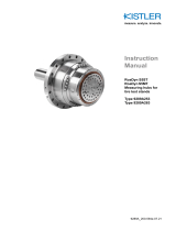
RoaDyn S260
Measuring hub for
tire test machines
Type 9289A113
9289A_002-535e-07.21


Foreword
Page 1
Foreword
Thank you for choosing a Kistler quality product
characterized by technical innovation, precision and long
life.
Information in this document is subject to change without
notice. Kistler reserves the right to change or improve its
products and make changes in the content without
obligation to notify any person or organization of such
changes or improvements.
©2011 … 2021 Kistler Group. All rights reserved. Except
as expressly provided herein, no part of this manual may
be reproduced for any purpose without the express prior
written consent of Kistler Group.
Kistler Group
Eulachstrasse 22
8408 Winterthur
Switzerland
Tel. +41 52 224 11 11
Kistler Instrumente GmbH
Umberto-Nobile-Str. 14
71963 Sindelfingen
Deutschland
Tel. +49 7031 3090 0
info.de@kistler.com
www.kistler.com

RoaDyn S260 Measuring Hub for Tire Test Machines Type 9289A113
Page 2
Content
1.Introduction .................................................................................................................................. 4
2.Important notes ........................................................................................................................... 5
2.1For your safety .................................................................................................................... 5
2.2Warnings ............................................................................................................................. 6
2.3How to treat the instrument ................................................................................................. 7
2.4Hints for using the operating instructions ............................................................................ 7
2.5What happens after modifications? ..................................................................................... 7
3.General description of the instrument ...................................................................................... 8
3.1Field of application for multi-component measuring hub S260 ........................................... 8
3.2RoaDyn S260 measuring chain digital and analog ............................................................. 9
4.Installation ................................................................................................................................... 10
4.1Important Notes ................................................................................................................. 10
4.2Dimensions......................................................................................................................... 10
4.3Preparation for mounting the measuring hub on the test bench ....................................... 11
4.3.1Measuring hub mounting location ..................................................................................... 12
4.3.2Mounting on tire test bench ............................................................................................... 13
4.3.3Mounting oil hoses ............................................................................................................ 14
4.4Connection and cables for the measuring system ............................................................... 16
4.4.1Connection of RoaDyn S260 with digital electronics KiRoad Tire Testing Type 9820A… 17
4.4.2Connection of RoaDyn S260 with analog electronics Type 5633A1 ................................ 17
5.Oil lubrication ............................................................................................................................ 18
5.1Oil connection .................................................................................................................... 18
5.2Oil circulating lubrications ................................................................................................. 19
5.3Oil lubrication system ......................................................................................................... 20
6.Operation .................................................................................................................................... 21
6.1Permissible loads on the measuring hub .......................................................................... 21
6.2Service life of bearings ...................................................................................................... 21
6.3Setup DAQ ........................................................................................................................ 21
6.3.1With digital electronics Type 9820A… .............................................................................. 21
6.3.2With analog electronic Type 5633A1 ................................................................................ 21
6.4Mounting adapter flange ................................................................................................... 23
6.5Run the system ................................................................................................................. 23
7.Maintenance ............................................................................................................................... 24
7.1On-side Fx calibration by the use of deadweights ............................................................. 24
7.1.1Basics .............................................................................................................. 24
7.1.2Preparation of equipment .................................................................................................. 24
7.1.3Deadweight calibration procedure .................................................................................... 25
7.2Checking calibration, function test and recalibration ........................................................ 32
7.2.1Checking calibration and function test .............................................................................. 32
7.2.2Recalibrating the measuring hub ...................................................................................... 32
7.3Maintenance work ............................................................................................................. 32
7.3.1General .............................................................................................................. 32

Content
Page 3
8.Troubleshooting ......................................................................................................................... 33
8.1Fault location and rectification ........................................................................................... 33
8.2Defective measuring hub ................................................................................................... 34
9.Technical data ............................................................................................................................ 35
10.Appendix ..................................................................................................................................... 36
10.1Rear plate for oil hose mounting ........................................................................................ 36
10.2Screw for oil hose fixation .................................................................................................. 37
10.3EC Declaration of conformity ............................................................................................. 38
Total pages 39

RoaDyn S260 Measuring Hub for Tire Test Machines Type 9289A113
Page 4
1. Introduction
Please take the time to thoroughly read this instruction
manual. It will help you with the installation, maintenance,
and use of this product.
To the extent permitted by law Kistler does not accept
any liability if this instruction manual is not followed or
products other than those listed under Accessories are
used.
Kistler offers a wide range of products for use in
measuring technology:
Piezoelectric sensors for measuring force, torque,
strain, pressure, acceleration, shock, vibration and
acoustic emission
Strain gage sensor systems for measuring force and
moment
Piezoresistive pressure sensors and transmitters
Signal conditioners, indicators and calibrators
Electronic control and monitoring systems as well as
software for specific measurement applications
Data transmission modules (telemetry)
Kistler also develops and produces measuring solutions
for the application fields of engines, vehicles, manufac-
turing, plastics and biomechanics sectors.
Our product and application brochures will provide you
with an overview of our product range. Detailed data
sheets are available for almost all products.
If you need additional help beyond what can be found
either on-line or in this manual, please contact Kistler's
extensive support organization.

Installation
Page 5
2. Important notes
It is essential for you to study the following information,
compliance with which is for your personal safety during
use and will ensure long, fault-free operation of the
instrument.
2.1 For your safety
This instrument has been thoroughly tested and has
left the factory in perfectly safe condition. In order to
maintain this condition and to ensure hazard-free
operation, the user must comply with the information
and warning notes contained in these operating
instructions.
The measuring hub must only be installed, operated
and serviced by personnel who are familiar with the
instrument and are adequately qualified.
If it is determined that safe operation is no longer
possible, the instrument must be shut down and made
safe against accidental start-up.
Safe operation is no longer possible
when the unit shows visible signs of damage,
when the unit is no longer operating,
after lengthy storage under unsuitable conditions,
after very rough transport conditions
For wheel measurements, secure the measuring hub
to the test bench according to the directions! For
details, read chapter 4.3 Mounting the Measuring
Hub.
Secure all parts mounted on the shaft according to
the anticipated forces!

RoaDyn S260 Measuring Hub for Tire Test Machines Type 9289A113
Page 6
2.2 Warnings
The measuring hub is designed and manufactured by
Kistler Instrumente AG according to the best enginee-
ring knowledge and the latest state of technology.
These components, however, are not designed for
indefinite use. They are highly stressed high-perfor-
mance products and as such have a limited life, since
they are subjected to wear and tear and, in extreme
cases, fati
g
ue stress.
For this reason, the following safety measures must be
strictly observed:
The loading for the measuring hub and accessories
must not exceed the overload ranges specified in the
Type 9289A data sheet
If the user has reason to believe that these overload
ranges have been exceeded, all parts must be tested,
according to the situation (for example: visual
inspection, crack analysis etc.)
All parts must be subjected to a visual inspection on
each occasion before use
As soon as any signs of damage (crack, deformations
etc.) are visible, further use is prohibited
Strict compliance is required with the operating
instructions during mounting, in particular concerning
tightening torques for screws, the correct fitting of
parts, adequate clearance for the fixation arms and
safe cable installation
A crack test must be carried out after the first 100
hours operating time
After 500 hours operating time, the instrument wheel
and the accessories must be subjected to a crack test
periodically
For wheel force measurements, secure the
measuring hub to the test bench correctly!

Installation
Page 7
2.3 How to treat the instrument
The measuring hub may only be used under specified
environmental and operating conditions
Protect the signal output of the instrument against
contamination and do not touch it with your fingers.
Place supplied cover over connection when not in use
Protect the measuring hub while it is not in use by
keeping it in the supplied transport and storage box
2.4 Hints for using the operating instructions
We recommend reading the entire operating instructions
as a matter of principle. If you’re in a hurry, however, and
you’ve already gathered experience with Kistler
measuring hubs, you can confine your reading to the
information that applies to your application needs.
We have arranged these instructions so that you can find
the information you need without difficulty.
Please keep these Operating Instructions in a safe place
where they can be consulted at any time.
If the instructions get lost, just contact your Kistler
distributor and they will be replaced without delay.
All information and directives in these instructions may be
modified at any time without prior notification.
2.5 What happens after modifications?
Modifications to instruments result in alterations of the
operating instructions as a rule. In such cases, enquire at
your Kistler distributor about the possibilities of updating
your documentation.

RoaDyn S260 Measuring Hub for Tire Test Machines Type 9289A113
Page 8
3. General description of the instrument
3.1 Field of application for multi-component measuring hub S260
The measuring hub is used for rolling resistance
measurements according the commonly used global
regulations (ISO 28580, SAE J1269, ECE R117) for truck
tires above Load Index 121. Therefore, two of the
orthogonal components (Fx and Fz) which are acting on
the shaft respectively on the tire patch will be measured.
The measuring hub has a high accuracy with lowest
crosstalk and thus the ability to measure the smallest
longitudinal forces (Fx) while a high normal force (Fz) acts
simultaneously. As a result of the ability to measure Fz,
the measuring hub is perfectly suited to be used for test
stand controlling.
The measuring hub measures the active wheel force
independently of its point of application. Both the average
force and dynamic force changes can be measured. The
useful frequency range depends mainly on the resonant
frequency of the entire test rig.
Fig. 1: Measuring hub Type 9289A113

Installation
Page 9
3.2 RoaDyn S260 measuring chain digital and analog
Fig. 2: Digital measuring chain RoaDyn S260
Fig. 3: Analog measuring chain RoaDyn S260

RoaDyn S260 Measuring Hub for Tire Test Machines Type 9289A113
Page 10
4. Installation
4.1 Important Notes
The measuring hub Type 9289A113 is a precision
instrument whose inherent accuracy will only be
maintained when the instrument is carefully handled.
Please take note of the following requirements:
Do not drop the measuring hub or expose it to any
hard knocks! The maximum force of such shocks
could exceed the measuring range of the instrument
and cause permanent deformations
Do not use a hammer for positioning the rim adapter,
since hammer blows can cause deformation of the
bearings or rim
In the following chapters, you will find information on
installing the measuring hub and basic details for setting
up the test rig.
4.2 Dimensions
Fig. 4: Dimensions of RoaDyn S260

Installation
Page 11
4.3 Preparation for mounting the measuring hub on the test bench
Please comply with the following notes for correct
mounting of the measuring hub:
The measuring hub must only be installed by
personnel who are familiar with the instrument and are
adequately qualified
Before connecting the cable to the measuring hub
clean both sides of the connector (measuring hub and
cable) with the cleaning and insulation spray Type
1003. Check orientation by bringing the mark on the
connector of the cable in line with the hole of the
metal sheet (Fig. 5). Plug in the cable until a proper
contact is made
Before mounting the measuring hub on a test bench
or another test device, connect the oil hoses as
explained in chapter 5.1 and mount all additional
equipment on the shaft rear side such as resolver or
slip ring
Before mounting the measuring hub on a test bench
or another test device, check that the mounting
surface is flat and clean. Uneven and dirty contact
surfaces cause internal distortions, which will expose
the individual force sensors to additional high shear
stresses which could reduce the accuracy
Fig. 5: Connecting

RoaDyn S260 Measuring Hub for Tire Test Machines Type 9289A113
Page 12
4.3.1 Measuring hub mounting location
The measuring hub could be mounted either on the left or
the right side of the drum (Fig. 6).
Fig. 6: Horizontal drum axle with different positions of
the measuring hub
As the coordinates are in fixed relation to the measuring
hub they remain for all positions the same:
Fx: Longitudinal force (rolling resistance)
Fz: Normal force
To avoid overload on the X direction, ensure that the
measuring hub is mounted in the correct orientation.
The measuring hub is provided with oil lubrication. It must
be performed with the specific oil-supply related to the
mounting position as described in the picture below (Fig.
7).

Installation
Page 13
4.3.2 Mounting on tire test bench
Standard mounting of the measuring hub is done using
the twelve M16x60 mm screws, supplied at delivery.
These screws are on a 410 mm pitch circle diameter and
must be tightened with a torque of 180 … 190 Nꞏm.
The positioning is given by two 10 mm pins which are
also located on the pitch circle diameter 410 mm.
The positioning pins allow accurate mounting and
remounting of the measuring hub.
Therefore, adjustment of position according the
regulations must be done on a second layer.
Fig. 7: Measuring hub with wheel mounted on tire test
bench
Ensure that the measuring hub makes absolutely flat
contact. Even the slightest gap will produce unwanted
elasticity and cause a reduction in the resonant fre-
quency of the measuring arrangement. Therefore,
examine all structures for vibration
Wherever possible, the connecting cable should
remain permanently connected to the measuring hub
Fit the connecting cable and the oil tubes so that it
cannot shear off or be ripped out during operation

RoaDyn S260 Measuring Hub for Tire Test Machines Type 9289A113
Page 14
4.3.3 Mounting oil hoses
In order to not create any force interaction between
measuring hub and test machine, the piping has to be
done as follows:
Fig. 8: Piping
Oil hoses should be taken to the rear side without
bending. They should be guided by using a
corresponding plate (not within the scope of delivery, see
appendix 10.1).
Check the distance between oil connector (supplied
within the scope of delivery) and rear plate according the
picture below and adjust length of oil hoses if necessary.
Fig. 9: Distance between rear plate and oil connector
Distance between rea
r
Plate and oil connector
2 … 4 mm

Installation
Page 15
Fig. 10: Plug in the oil hoses into the 90° oil connector
(red highlighted)
Mount screws (see appendix 10.2) and nuts in the
corresponding holes and adjust the level in order to avoid
any force interaction to the measuring hub.
Fig. 11: Mount screws and nuts

RoaDyn S260 Measuring Hub for Tire Test Machines Type 9289A113
Page 16
Fig. 12: Hose fixation by using cable straps
To avoid any force interaction on the dynamometer,
ensure that the oil hoses are not contacted hard by other
parts. This should also be checked during moving of the
sledge.
4.4 Connection and cables for the measuring system
After proper mounting of the measuring hub connect
the two cables with the electronics (see 3.2 and
instruction manual of the used electronics)
Ensure accuracy and cleanliness in all work involving
electrical connections. Only remove the cover caps
from the connections immediately before connecting a
cable

Installation
Page 17
4.4.1 Connection of RoaDyn S260 with digital electronics KiRoad Tire Testing
Type 9820A…
Fig. 13: Digital measuring chain
4.4.2 Connection of RoaDyn S260 with analog electronics Type 5633A1
Fig. 14: Analog measuring chain

RoaDyn S260 Measuring Hub for Tire Test Machines Type 9289A113
Page 18
5. Oil lubrication
The oil circulating helps to keep the bearing friction low
and is essential for a long lifetime of the bearings. In
addition, the oil also helps to cool the measuring hub.
For tests under hard conditions (high speed/high loads)
the lubrication system could be upgraded by using an
additional cooling system (e.g. secondary water-cooling
system).
5.1 Oil connection
To ensure proper oil lubrication, the connections on the
top side must be used as oil inlet and the connections on
the bottom side are for oil outlet.
If the oil inflow and outflow of the measuring hub are
not in the correct position, the bearings or the seals
will be damaged within a short period because of
improper oil lubrication or overpressure in the
measurin
g
hub!
Fig. 15 Oil connections (Top oil in/bottom oil out)
/