Page is loading ...

Cables
-
C20 through C21

Cables for Gateway 20 through 21 PAGE 1
© JBM Electronics Co. 1-800-489-7781 www.jbmelectronics.com
File Name: cable_c20_c21.doc
Revision Date: March 23, 2006
Revision Level: 1.0
FCC Notice
Warning: This equipment generates, uses, and can radiate radio frequency
energy; and if not installed and used in accordance with the instruction manual,
may cause interference to radio communications. It has been tested and found
to comply with the limits for a Class A computing device pursuant to Subpart J of
part 15 of FCC Rules, which are designed to provide reasonable protection
against such interference when operated in a commercial environment.
Operation of this equipment in a residential area is likely to cause interference, in
which case, the user, at his own expense, will be required to take whatever
measures may be required to correct the interference.
The Gateways are listed by a Nationally Recognized Testing Laboratory.
All copyrights are held by their respective owners.
NOTICE:
Specifications described in this manual are
subject to change without notice.
Gateway 40 - 940 Cables
Copyright 2004 by JBM Electronics Co.
For further information, contact:
JBM Electronics Co.
4645 LaGuardia
St. Louis, MO 63134
Phone: (314) 426-7781
Fax: (314) 426-0007
Internet: http://www.jbmelectronics.com

Cables for Gateway 20 through 21 PAGE 2
© JBM Electronics Co. 1-800-489-7781 www.jbmelectronics.com
C20 –C21
Port Cable Description Cable Order
Number
Table
Serial
9F to 9M DCE Cable 6foot C/9SF-9M-DCE-6’ Pg. 3
9F to 25M DCE Cable 6foot C/9SF-25M-DCE-6’ Pg. 3
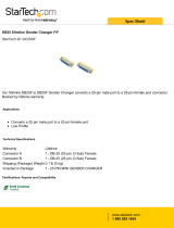
9F to 9F Straight Gender Changer C/9FF-XGENDER Pg. 4
DE-9M RS232 DTE async
(Comport)
25F to 25F Straight Gender Changer C/25FF-XGENDER Pg. 4
LAN
RJ-45 Straight N/A Pg. 5 RJ-45 Ethernet
RJ-45 Crossed C/CAT5-CROSS Pg. 5
Modem
RJ-11 Dial-Tone async RJ-11 Straight N/A Pg. 6

Cables for Gateway 20 through 21 PAGE 3
© JBM Electronics Co. 1-800-489-7781 www.jbmelectronics.com
9F to 9M/F (DCE)
This table lists the required RS-232 wiring required to provide a DCE interface for a
Gateway Comm. Port. The pins should be connected from one connector to the other
using the transpositions indicated. This cable is used for modem emulation.
Units Supported
• C20
JBM Electronics Part Number: C/9SF-9M-DCE-6’
9F to 25M/F
(DCE)
This table lists the required RS-232 wiring required to provide a DCE interface for a
Gateway Comm. Port. The pins should be connected from one connector to the other
using the transpositions indicated. This cable is used for modem emulation.
Units Supported
• C20
JBM Electronics Part Number: C/9SF-25M-DCE-6’
9-Pin Female to 9-Pin Male
To JBM Device
DIRECTION
To Async Device
1 tied to 6
Å
4
2
Å
3
3
Æ
2
4
Æ
6 tied to 8
5 GND 5
- - -
7
Æ
1
8
Å
7
- - -
Converts Com Port to DCE
9-PIN FEMALE TO 25-PIN MALE
JBM Device
DIRECTION
Async Device
1 tied to 6
Å
20
2
Å
2
3
Æ
3
4
Æ
5 tied to 6
5 GND 7
- - -
7
Æ
8
8
Å
4
- -
Converts Com Port to DCE

Cables for Gateway 20 through 21 PAGE 4
© JBM Electronics Co. 1-800-489-7781 www.jbmelectronics.com
25F to 25F Gender Changer
This is used to change a 9-pin male end connector to female.
Units Supported
• C20
JBM Electronics Part Number: C/9FF-XGENDER
25F to 25F Gender Changer
This is used to change a 25-pin male end connector to female.
Units Supported
• C20
JBM Electronics Part Number: C/25-XGENDER

Cables for Gateway 20 through 21 PAGE 5
© JBM Electronics Co. 1-800-489-7781 www.jbmelectronics.com
RJ-45 Straight
This table lists the Ethernet pins used in the Ethernet Port ETH0. For a straight-wired
connection the pins should be connected from one connector to the other without
transpositions or other wiring changes.
Units Supported
• C20
• C21
JBM Electronics Part Number: N/A
RJ-45 Crossed
This table lists the required Crossed-Wired Ethernet wiring required to provide cable
connection to the Gateway and a local PC. The pins should be connected from one
connector to the other using the transpositions indicated.
Units Supported
• C20
• C21
JBM Electronics Part Number: C/CAT5-CROSS
TABLE C STRAIGHT 10/100BASET
PIN DESCRIPTION
1 TD+
2 TD-
3 RD+
4
-
5
-
6 RD-
7
-
8
-
Used for HUB or Switch
TABLE D CROSSED 10/00BASET
CONNECTOR A CONNECTOR B
1 3
2 6
3 1
- -
- -
6 2
- -
- -
Used for direct PC connection

Cables for Gateway 20 through 21 PAGE 6
© JBM Electronics Co. 1-800-489-7781 www.jbmelectronics.com
RJ-11 Straight
This table lists the required pins used in the Modem cable used to connect the Gateways
to an asynchronous modem. Pins should be connected from one RJ-11 connector to the
other without transpositions or other wiring changes.
Units Supported
• C21
JBM Electronics Part Number: N/A
RJ-11 MODEM CABLE
PIN DESCRIPTION
1 Unused
2 Tip
4 Ring
5 Unused
Used for connecting a modem to the C21
/