Page is loading ...

MSA 1111 (L) Rev. 3 © MSA 2011 Prnt. Spec. 10000005389(B) Mat. 10089353
Doc. 10089353
The warranties made by MSA with respect to the product are voided if the product is not installed,
used, and serviced in accordance with the instructions in this manual. Please protect yourself and
your employees by following the instructions. Please read and observe the WARNINGS and CAU-
TIONS inside. For any additional information relative to use or repairs, call 1-800-MSA-2222 during
regular working hours.
See separate insert for NIOSH Approval Information: P/N 10122516
This manual must be read carefully by all persons who have or will have the
responsibility for using or servicing the product. Like any complex piece of
equipment, the Abrasi-Blast Respirator from MSA will perform as designed only
if it is used and serviced according to the instructions. Otherwise, it could fail
to perform as designed, and persons who rely on this respirator could sustain
serious personal injury or death.
INSTRUCTIONS
Abrasi-Blast
™
Respirator
"
WARNING

INTRODUCTION
NIOSH APPROVAL INFORMATION
CAUTIONS AND LIMITATIONS
A- Not for use in atmospheres containing less than 19.5
percent oxygen.
B- Not for use in atmosphere immediately dangerous to
life or health.
C- Do not exceed maximum use concentrations estab-
lished by regulatory standards.
D- Airline respirators can be used only when the respira-
tors are supplied respirable air meeting the require-
ments of CGA G-7.1 Grade D or higher quality.
E- Use only the pressure ranges and hose lengths speci-
fied in the User’s Instructions.
G- If airflow is cut off, switch to filter and/or cartridge and
immediately exit to clean air.
H- Follow established cartridge and canister change
schedules or observe ESLI to ensure that cartridges
and canisters are replaced before breakthrough
occurs.
J- Failure to properly use and maintain this product could
result in injury or death.
L- Follow the manufacturer’s User’s Instructions for
changing cartridges, canister, and/or filters.
M- All approved respirators shall be selected, fitted, used,
and maintained in accordance with MSHA, OSHA, and
other applicable regulations.
N- Never substitute, modfiy, add, or omit parts. Use only
exact replacement parts in the configuration as speci-
fied by the manufacturer.
O- Refer to User’s Instructions, and/or maintenance man-
uals for information on use and maintenance of these
respirators.
P- NIOSH does not evaluate respirators for use as surgi-
cal masks.
S- Special or critical User’s Instructions and/or specific
limitations apply. Refer to User’s Instructions before
donning.
S - SPECIAL OR CRITICAL USERS INSTRUC-
TIONS
The wearer must comply with the following MSA respirator
use limitations:
1. The limitations outlined in the applicable NIOSH
approval.
2. Any applicable limitation contained in a standard estab-
lished by a regulatory agency (such as OSHA) with
jurisdiction over the wearer.
3. Users must wear suitable protective clothing and pre-
cautions must be taken so that the respirator is not
worn in atmospheres that may be harmful to the
device.
a. Do not wear for protection against substances with
poor warning properties or those which generate
high heats of reaction with sorbent material in the
filter.
b. Make certain conditions of exposure are within the
limits for which the device is approved.
4. Refer to Tables 1, 3, and 5 for specific supply hose
and pressure limitations for the Abrasi-Blast. Also, for
more detailed information, refer to the specific approval
label at the end of the configuration.
5. The Advantage
®
4000 Facepiece is not
authorized for use without a nosecup.
6. This approval applies only when the device is supplied
with respirable air through 8 to 300 feet of air supply
hose within the pressure range of 35 - 40 pounds per
square inch gage.
7. A maximum of 12 sections of air supply hose may be
used in making up the maximum working length of
hose. Each section of coiled hose, regardless of
length, is considered 50 feet in length (max.: 6 sec-
tions).
8. Below 32° F, add the following nosecups to the
Ultravue
®
Facepiece: 471539, 471540, or 471541.
9. NIOSH approval information is included as a
supplement (P/N 10122516) to these instructions for
Abrasi-Blast Respirators.
2
MSA 1111 (L) Rev. 3- 10089353
TABLE OF CONTENTS
NIOSH Approval Information . . . . . . . . . . . . . . . . . . . . . .2
Special or Critical User Instructions . . . . . . . . . . . . . . . . .2
Description . . . . . . . . . . . . . . . . . . . . . . . . . . . . . . . . . . . .5
Assembling the Respirator . . . . . . . . . . . . . . . . . . . . . . . .6
Unpacking and Inspection . . . . . . . . . . . . . . . . . . . . . . . .6
Donning . . . . . . . . . . . . . . . . . . . . . . . . . . . . . . . . . . . . . .8
Using the Respirator . . . . . . . . . . . . . . . . . . . . . . . . . . . 12
Removing the Respirator . . . . . . . . . . . . . . . . . . . . . . . .14
Cleaning and Disinfecting . . . . . . . . . . . . . . . . . . . . . . . .15
Maintaining the Respirator . . . . . . . . . . . . . . . . . . . . . . .16
Repositioning the Lens Housing Assembly . . . . . . . . . .17
Accessories . . . . . . . . . . . . . . . . . . . . . . . . . . . . . . . . . .18
Abrasi-Blast Hood Styles and Accessories . . . . . . . . . . .20
Facepiece Assemblies . . . . . . . . . . . . . . . . . . . . . . . . . .21
Flow Control Devices . . . . . . . . . . . . . . . . . . . . . . . . . . .23
Air-Supply Hoses . . . . . . . . . . . . . . . . . . . . . . . . . . . . . .25
Quick-Disconnects . . . . . . . . . . . . . . . . . . . . . . . . . . . . .26

INTRODUCTION
RESPIRATOR USE LIMITATIONS DUO-FLO™
MODE
Maximum Use Concentration — Duo Flo Mode
Do not exceed ANY of the applicable maximum use con-
centrations listed in Table 1.
Mixtures of Contaminants —
NIOSH allows this respirator to be used for protection
against a mixture of contaminants that are present simulta-
neously or used alternately against one contaminant then
another (using the same filters) if the mixture meets the
following conditions:
a. The filter must be approved for all contaminants
present.
b. Contaminants present simultaneously must be
below IDLH levels for the specific contaminants. If
any one contaminant in the mixture exceeds the
IDLH concentration then the entire mixture must be
treated as IDLH and the respirator cannot be used
(except for escape from particulates with appropri-
ate filter).
Exposure Limits for Mixtures
The American Conference of Government Industrial
Hygienists (ACGIH) publishes the following information to
determine the TLV of a mixture.
First, determine the total concentration of the chemical
mixture (C
Mixture
) from the individual contaminant con-
centrations (C
1
, C
2
, C
3
...) using the following formula:
C
Mixture
= C
1
+ C
2
+ C
3
+ ...
The TLV of the mixture is found by using the following for-
mula where T
1
, T
2
, T
3
... are the individual contaminant
TLVs and C
1
, C
2
, C
3
, ... are the individual contaminant
concentrations:
Only use these equations if the contaminants present are
actually mixed. Some substances do not mix and may be
present separately, for example, in pockets or at different
levels. In that case, the lowest TLV of the substances pre-
sent must be used to determine the appropriate respirator
category for protection against all contaminants present.
Exposure Limits
A listing of acceptable exposure limits from the following
sources.
• American Conference of Government Industrial
Hygienists (ACGIH)
• Occupational Safety and Health Administration (OSHA)
• National Institute for Occupational Safety and Health
(NIOSH)
• American Industrial Hygiene Association (AIHA)
Contact MSA at 1-800-MSA-2222 for information.
3
MSA 1111 (L) Rev. 3 - 10089353
RESPIRATOR TYPE RESPIRATORS WITH
PARTICULATE FILTERS
RESPIRATOR USE OR FILTER
CARTRIDGES
Routine Use in Air-Supplied
Mode - Including Entry
Continuous Use and 1,000 Times Exposure Limit
Non-Emergency Egress
Routine Use in Air-Purifying
Mode - Including Entry,
Continuous Use, Non- 50 Times Exposure Limit
Emergency Egress and/or
Moving from Station-to-
Station
Emergency Escape in Air-
Purifying Mode Unlimited
Table 1

4
MSA 1111 (L) Rev. 3- 10089353
NOTES

DESCRIPTION
The Abrasi-Blast Respirator may be ordered in numerous
configurations. To identify the configuration that you have
received, match the part numbers of your unit with those
listed in Table 2.
You may wish to make a permanent record of your com-
plete system as an aid for ordering replacement parts. Use
the listing below to keep a record of your configuration in
this manual.
Assembly Part No.
Hood _________
Cover Lens _________
Facepiece _________
Flow Control Valve _________
Air-Supply Hose _________
During abrasive blasting operations, the facepiece lens is
protected by two to four flat-glass cover lenses. Each
cover lens is removed by two pull-tabs when it becomes
so scratched that vision is reduced. Respirator approval
requires the use of the proper length of approved air-sup-
ply hose, approved fittings, and a respirable air source.
When using the Duo-Flo Respirator, the user breathes
through the filter until connecting the air-line. The supplied-
air mode of operation may be used for long periods of time
without depleting the filter. The air-purifying mode of oper-
ation also may be used for extended periods of time when
an air source is not available. During use, the respirator
remains in the supplied-air mode of operation so long as
the user is connected to an air-line air source. The air-puri-
fying mode of operation is entered “automatically” if the
air-line air source is disconnected or lost for any reason.
ALL CONFIGURATIONS
Constant Flow Adjustable Valves — Adjustable
valves allow the user to vary air flow within NIOSH-
required flow rates.
Duo-Flo — The Duo-Flo valve, used in conjunction with
the Ultra filter (P/N 816255), enables the user to enter and
escape from contaminated atmospheres without using the
air-line air supply.
REQUIRED TOOLS
Abrasi-Blast Respirator systems may be assembled with
standard tools and materials following good work prac-
tices. The assembly tips below may help:
1. All tapered pipe connections should be wrapped with
pipe sealing tape (applied one thread back from the
end) before assembly.
2. Open-end wrenches and slip-joint pliers should be
used to tighten all threaded connections, unless specif-
ically noted otherwise.
3. Test all threaded connections under pressure with a
commercial leak-test solution or soapy water. If a leak
is detected, locate the source and correct it before
using the respirator.
5
MSA 1111 (L) Rev. 3 - 10089353
Table 2
SOME STANDARD ABRASI-BLAST RESPIRATOR ASSEMBLIES
(Includes one lens cartridge [.12 untempered] and instruction manual
Abrasive
Mask
Assy.
P/N
Hood
Facepiece
(Medium)
P/N
Breathing
Tube
P/N
Belt
P/N
Flow Control Assy.
Type
Quick-
Disconnect
Supply
Hose
Union
Adapter
P/N
P/N Style P/N
Pressure
Supply PSI
468720 468725 Shoulder 472666 470734 9961 463278 10-15 Snap-Tite Order Sep. 69542
468716 468724 Waist 472666 470734 9961 463278 10-15 Snap-Tite Order Sep. 69542
468722 468725 Shoulder 472666 470734 9961 460814 35-40 Snap-Tite Order Sep. 69542
468718 468724 Waist 472666 470734 9961 460814 35-40 Snap-Tite Order Sep. 69542
10117170 468725 Shoulder 472666 470734 9961 479114 32-37 CEJN Order Sep. 69542
10117169 468724 Waist 472666 470734 9961 479114 32-37 CEJN Order Sep. 69542

ASSEMBLING THE RESPIRATOR
UNPACKING & INSPECTION
The Abrasi-Blast Respirator consists of the following sub-
assemblies:
• hood
• facepiece
• breathing tube
• support belt
• collar
• lens housing assembly
• waist strap
• adjustable valve-connector or Duo-Flo adapter
• air-supply hose socket assembly
• cover lens cartridge
Thoroughly inspect the respirator and all com-
ponents when received and before using. Read
and observe all NIOSH approval limitations as
they apply to using the Abrasi-Blast Respirator.
Respirator Assembly
Note: Follow the steps below to assemble the respirator.
Do not don the respirator until all steps in this section are
completed.
1. Install the breathing tube.
Note: The breathing tube may be worn either outside or
under the hood. Follow the instructions that apply to
assemble the breathing tube.
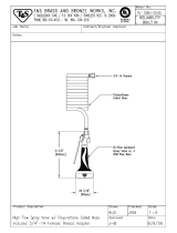
a. If the breathing tube
is worn outside the
hood, locate the 3/4”
hole in the front of
the hood. Push the
male threaded end of
the breathing tube
through the hole until
the hood seals
around the tube at
the first to sixth cor-
rugation in the
breathing tube.
b. If the breathing tube
is worn under the
hood, locate the 3/4”
metal plug in the col-
lar inside the hood
and remove it by
stretching the rubber
grommet.
c. Install the plug in the
3/4” hole in the front of
the hood by stretching
the rubber material.
d. Push the threaded
end of the breathing
tube through the hole
in the collar until the
rubber grommet
seals around the
breathing tube at the
third corrugation.
e. When using the parka hood (P/N 807592), push the
threaded end of the breathing tube through the elas-
tic collar located on the waist area of the hood.
2. Assemble the facepiece to the hood and breathing
tube:
a. Unfasten the Velcro closure on the collar and insert
the facepiece into the hood.
b. Align the lens hous-
ing assembly with
the large opening in
the hood.
c. Stretch the rubber
front of the hood
over the lens hous-
ing so that the rub-
ber forms a seal in
the channel between
the door frame and
the lens housing
assembly.
6
MSA 1111 (L) Rev. 3- 10089353
"
CAUTION

COMPONENT ASSEMBLY
d. Refasten the Velcro closure.
e. Attach the breathing
tube to the facepiece
by threading the cou-
pling nut onto the
breathing tube. Be
sure the gasket is in
the coupling nut.
Hand-tighten.
3. Select the proper cover lens for the job. (Use Table 3
as a general guide to choose the cartridge.) A thinner
cover lens may not give satisfactory service life
because heavy abrasive may wear holes in the lens.
a. To open the lens
housing door, grasp
the top corner of the
plastic door and pull
it away from the
hood.
b. Open the package of protective lens cartridges.
c. Insert the lens car-
tridge into the lens
housing. The car-
tridge can be
installed so that the
pull-tabs are either at
the top or the bottom
of the lens housing.
NOTE: Be sure the 2 pull-tabs are not caught in the lens
door opening.
d. Close the lens housing door to force the lens car-
tridge into place. Pull on the door without flexing the
latch to be sure the door is secured.
4. If a filter cartridge is to be used, refer to the Replacing
the Filter Cartridge section of these instructions.
NOTE: The filter cartridge is not approved for use on the
combination Duo-Flo type respirator.
5. Disconnect the socket
assembly from the
valve-connector body
and thread the socket
assembly on the air-
supply hose.
6. Connect the opposite
end of the air-supply
hose to a respirable air
source.
NOTE: The pressure gauge assemblies listed below are
available with fittings. The pressure gauge assembly is
connected to the air source where the air-supply hose
from MSA is attached.
Part No. Description
476734 Snap-Tite
476735 Foster
476737 Hansen
476738 CEJN
476739 Foster (w/check valve)
476740 Hansen (w/check valve)
7
MSA 1111 (L) Rev. 3 - 10089353
Lens Type Type of Service
.090” untempered Medium abrasive blasting
.090” tempered Medium abrasive blasting and added
protection against glass breakage due
to rough handling
.120” untempered Heavy abrasive blasting
Table 3

DONNING
DONNING
These steps must be followed each time the respirator is
used.
• This respirator must be used only by trained
personnel and according to MSA’s instruc-
tions.
• Do not use the respirator as an underwater
device.
• Wear impermeable protective clothing if
exposed to poisons which can be absorbed
by the skin.
• Wear appropriate protective clothing to pro-
tect your body from rebounding abrasive
material.
• This system must be supplied with res-
pirable air. See ANSI Z86.1-1973
[Compressed Gas Association Specification
G-7.1 for Quality Verification Level (Grade D)
Gaseous Air].
Misuse can result in serious personal injury or
death.
SECTION A: CONSTANT FLOW
Supplied-Air Type Respirators
1. Be sure that inlet air pressure is set to agree with the
valve-connector you are using. Use the information in
Table 4 as a guide.
• The air source must provide at least 4 cubic
feet per minute (cfm) to each respirator, and
maintain the required inlet pressure range
specified in this manual for the specific flow
control device selected.
• If the air supply pressure is greater than 15
psig, 40 psig, be sure to use a pressure reg-
ulator between the air supply and air-supply
hose. Adjust the regulator to deliver air at
the pressures specified by the valve-con-
nector you are using.
Misuse can result in serious personal injury or
death.
2. Reconnect the socket
assembly to the flow
control valve (valve-
connector), or Duo Flo
airline adapter
(Constant Flow pic-
tured)
3. Slide the belt clip of the flow control or the Duo-Flow
valve over the support belt. Don the support belt and
position the valve so that it will be on your left side.
4. Turn the air supply on. Check for leaks with a commer-
cial leak detection solution or soapy water. Tighten
connections as required. Turn off the air source.
NOTE: Attach the appropriate filter to the coupling nut at
the bottom of the Duo-Flo valve.
5. Turn the back of the hood and collar “inside-out,”
exposing the facepiece headstraps. The Velcro strip on
the collar does not have to be unfastened unless a
protective helmet is worn.
6. Adjust the facepiece headstraps so the end tabs are at
the buckles.
7. Grip the facepiece
between your thumb
and fingers with both
hands. Insert your chin
into the lower part of the
facepiece. Pull the face-
piece headstraps over
your head. Smooth the
straps flat against your
head.
a. Support the facepiece by holding the breathing tube
at the coupling nut assembly with one hand.
b.Tighten the lower (neck) straps. Pull the straps
straight back, not out.
c. Tighten the side (tem-
ple) straps.
d. For the Ultravue Facepiece: Tighten the top
(forehead) strap to position the lens for best vision
and to support the weight of the facepiece.
8. Skip section B. Refer to Section C. Air-Tightness Test
(Face-to-Facepiece Seal).
8
MSA 1111 (L) Rev. 3- 10089353
"
WARNING
"
WARNING

SECTION B:
Combination Duo-Flo Type Respirators
1. Be sure that inlet air pressure is set to agree with the
valve-connector you are using. Use the information in
Table 4 as a guide.
The air source must provide at least 4 cubic
feet per minute (cfm) to each respirator, and
maintain an inlet pressure within the range of
35 - 40 psig for single exhalation valve masks
and 32 - 37 psig for dual exhalation valve
masks. If the air supply pressure is greater
than 40 psig (37 psig for dual exhalation valve
masks), be sure to use a pressure regulator
between the air supply and air-supply hose.
Adjust the regulator to deliver air at 40 psig.
Misuse can result in serious personal injury or
death.
2. Reconnect the socket assembly to the Duo-Flo valve.
3. Attach the appropriate filter to the coupling nut at the
bottom of the Duo-Flo valve.
4. Connect the breathing tube to the opening at the top of
the Duo-Flo tube.
5. Turn the back of the hood and collar “inside-out,”
exposing the facepiece headstraps. The Velcro strip on
the collar does not have to be unfastened unless a
protective helmet is worn.
6. Adjust the facepiece headstraps so the end tabs are at
the buckles.
7. Grip the facepiece
between your thumb
and fingers with both
hands. Insert your chin
into the lower part of
the facepiece. Pull the
facepiece headstraps
over your head.
Smooth the straps flat
against your head.
a. Support the facepiece by holding the breathing tube
at the coupling nut assembly with one hand.
b. Tighten the lower (neck) straps. Pull the straps
straight back, not out.
c. Tighten the side
(temple) straps.
d. For the Ultravue Facepiece: Tighten the top
(forehead) strap to position the lens for best vision
and to support the facepiece weight.
SECTION C:
Air Tightness Test (Face-to-Facepiece Seal)
If the breathing tube is worn under the hood,
move your head from side to side as well as up
and down to check for freedom of head move-
ment. If head movement is restricted, or this
method compromises the face-to-facepiece
seal in any way, wear the breathing tube on the
outside of the hood only.
1. Supplied-Air
Respirators Only:
Place the palm of your
hand firmly over the
breathing tube coupling
nut or place your thumb
over the breathing tube
opening inside the cou-
pling nut.
2. Combination Duo-Flo Type Respirators Only:
Place your hands tightly over the inlet(s) of the filter.
3. Inhale gently so that the facepiece collapses against
your face. Hold your breath for 10 seconds.
4. The facepiece should remain collapsed if the seal is
air-tight.
5. If the facepiece does not remain collapsed, readjust
the head harness straps and re-test.
6. If an air-tight seal cannot be obtained and leakage is
not caused by facial seal leakage, check the facepiece
and breathing tube for leaks. (See the Maintaining the
Respirator section). Locate the problem and correct
before using the respirator.
9
MSA 1111 (L) Rev. 3 - 10089353
DONNING
"
WARNING
"
WARNING

DONNING
This device may not seal properly with your
face if you have a beard, gross sideburns or
similar physical characteristics (see ANSI
Z88.2-1980). An improper facial seal may allow
non-respirable air to leak into the facepiece,
reducing or eliminating respiratory protection.
If such conditions exist, YOU, the user, assume
all risks of respiratory injury or death which
may result. The face-to-facepiece seal must be
tested before each use. Misuse can result in
serious personal injury or death.
SECTION D:
Respirator Fit Tests
A qualitative or quantitative respirator fit test must be carried
out for each wearer of a combination air-supplied and air
purifying type respirator. The test shall be performed in the
air-purifying mode of operation and is necessary in order to
determine the amount of protection the respirator will provide
while being used in the air-purifying mode.
Qualitative Test
If the wearer of the respirator passes a qualitative fit test,
the respirator can be worn in contaminant (particulate)
concentrations up to the maximum use listed in Table 4.
Quantitative Test
If the wearer of the respirator performs a quantitative fit
test, the respirator can be worn in contaminant (particu-
late) concentrations determined by the results of the test,
but not to exceed the maximum use listed in Table 4.
In addition to the above limitations, the wearer must not
exceed the limitations listed in the applicable NIOSH
Approval or any maximum use concentration controlled by
OSHA regulations.
The user assumes all risks of death or serious
bodily injury which can result if a fit test is not
performed, or if the respirator limitations are
not followed.
Respirator fit test and protection factors are explained fully
in ANSI Z88.2, “Practices for Respiratory Protection,” pub-
lished by the American National Standards Institute.
SECTION E:
Final Hookup
1. If wearing a protective helmet, see Step 2. Otherwise,
proceed as follows:
a. Pull the respirator
collar down around
your neck. The col-
lar is designed to
stretch over your
shirt or coverall col-
lar to help seal out
dust.
b. Pull the back of the hood down in place on your
shoulders. On the waist-length model, attach the
waiststrap loosely to minimize restrictions to head
movement.
2. If wearing a protective
helmet, you may wish
to either remove and
reverse the suspension
so the bill of the helmet
is in the back or wear it
in the standard manner
with the bill in front.
NOTE: A protective helmet cannot be used with the duck
cloth hood.
a. Unfasten the Velcro
strip on the collar.
Don the helmet with
the bill to the rear or
front.
b. Pull the collar down around your neck and fasten
the Velcro strip on the collar. The collar should be
over your shirt or coverall to help seal out dust.
c. Pull the back of the hood down in place on your
shoulders. On the waist-length model, attach the
waiststrap loosely to minimize restrictions to head
10
MSA 1111 (L) Rev. 3- 10089353
"
WARNING
"
CAUTION
Table 4
Facepiece Type Maximum Use Concentration
Full facepiece 50 times the TLV for the
contaminant

DONNING
movement.
3. Turn the air-supply on.
4. Constant Flow Type Respirators: Connect the
breathing tube coupling nut to the valve connector.
Hand-tighten. Pull on the air-supply hose to test the
connection.
5. Duo-Flo Type Respirators: Connect the socket
assembly to the Duo-Flo valve when it is desired to
switch from the air-purifying mode to the supplied-air
mode of operation.
All Abrasi-Blast Respirators are equipped with a heavy
rubber hood to provide limited protection to the user’s
head and neck from rebounding abrasive materials. The
hood also provides limited protection to the facepiece lens
by using removable glass lens covers. For additional spec-
ifications of Type “CE” respirators, see Title 42 CFR, Part
84, Subpart J.
Abrasi-Blast Respirators are available in waist, shoulder,
and parka models and may be used with the breathing
tube outside or under the hood.
Waist Model Tube Out Waist Model Tube Under
Shoulder Model Tube Out Shoulder Model Tube Under
11
MSA 1111 (L) Rev. 3 - 10089353

USING THE RESPIRATOR
USING THE RESPIRATOR
• Do not use an Abrasi-Blast Respirator if air
contaminants are unknown, immediately
dangerous to life or health, or you cannot
escape without respiratory protective equip-
ment. The supplied-air Abrasi-Blast respira-
tor configuration does not afford respiratory
protection if the air supply fails.
• Do not use the Combination Duo-Flo configu-
ration of the Abrasi-Blast respirator in
atmospheres containing less than 19.5 per-
cent oxygen, in atmospheres exceeding the
limits for which the filter will provide pro-
tection.
• Do not use near flame or hot metal, because
hood material may burn. The hood material
is classified as self-extinguishing as
required by Federal Standard 191, Method
5910.
• Do not contact organic-based solvents
which may attack the hood material, air-
supply hose or other plastic components. A
partial list of such solvents is as follows:
* Benzene
* Methyl Ethyl Ketone (MEK)
* Ethylene Dibromide
* Tetrahydrofuran (THF)
* Ethyl Acrylate
* Acetonitrile
* Isobutyl Amine
* Petroleum-Based Solvents
• Return to a safe atmosphere and discard
the respirator immediately if discoloration,
crazing, blistering, cracking or other deteri-
oration of the hood material, air-supply hose
or other plastic components is observed.
Misuse can result in serious personal injury or
death.
Changing Cover Lenses
The outer cover lens should be removed when it gets dirty
or scratched. To change the cover lens, grasp one of the
pull-tabs on the corners of the lens and pull straight out.
The last protective lens in the cartridge has no pull-tab. It
is to be kept over the primary lens to protect its surface
from abrasive materials.
DO NOT remove a lens cartridge during abra-
sive work. The primary lens may be polycar-
bonate and will scratch easily. If the primary
lens is damaged, the entire lens housing
assembly must be replaced.
DO NOT remove the facepiece in a contaminat-
ed area to replace the lens cartridge. The con-
taminant will remain in the surrounding air
after abrasive blasting. Return to a safe atmos-
phere before removing the respirator. Misuse
can cause inhalation of the contaminant result-
ing in serious respiratory injury or death.
Supplied-Air Type Respirators:
Adjusting Air Flow on Adjustable Valve
Connectors
1. Push in on the adjust-
ing knob, then turn the
knob.
2. Turn the knob fully
clockwise (up) for mini-
mum air flow.
3. Turn the knob fully counter-clock-wise (down) for maxi-
mum air flow.
NOTE: The adjusting knob may vary air flow, but cannot
reduce flow below the required minimum 4 cfm rate when
the proper pressure is used at the inlet of the air-supply
hose from MSA.
Combination Duo-Flo Type Respirators:
Converting to Different Modes of Operation
1. When using the respirator in the air-purifying mode of
operation, the supplied-air mode is entered when an
air-line air supply is connected to the Duo-Flo valve.
The air-line inlet pressure must be 35-40 psig for sin-
gle exhalation valve facepieces and 32-37 psig for
dual-exhalation valve facepieces in order to maintain 4
cfm to the facepiece.
12
MSA 1111 (L) Rev. 3- 10089353
"
WARNING
"
CAUTION
"
WARNING

USING THE RESPIRATOR
2. When using the respirator in the supplied-air mode of
operation, the air-purifying mode is entered when the
air-line air supply is disconnected from the Duo-Flo
valve. The air-purifying mode is entered “automatically”
if the air-line source is lost for any reason.
Return to fresh air immediately if:
• Leakage is detected by smell, taste, or eye,
nose or throat irritation.
• High breathing resistance is encountered.
• Any feeling of nausea, dizziness or ill-being
develops.
Misuse can result in serious personal injury or
death.
13
MSA 1111 (L) Rev. 3 - 10089353
"
WARNING

REMOVING THE RESPIRATOR
DOFFING THE RESPIRATOR
Removing the Respirator
1. To remove the hood, air supply system and facepiece,
return to fresh air and clean the outer surfaces of the
respirator before removing the facepiece.
2. Unsnap the waist-strap on the waist-length model.
3. Lift the back of the
hood over your head.
4. If wearing a protective helmet, separate the Velcro
strips on the hood collar and remove the helmet.
5. Place your finger tips
behind the headstraps.
Place your thumbs on
the buckles. Pull the top
of the buckles away
from your head. Repeat
as needed to loosen
the headstraps. Grip
the facepiece by the
inhalation housing. Pull
the facepiece out, then
up over your head. To
remove the facepiece quickly, pull the facepiece away
from your face, then up over your head.
6. Disconnect the air-line quick-disconnect.
7. Turn the air supply off.
8. Disconnect the breathing tube from the flow control
valve.
14
MSA 1111 (L) Rev. 3- 10089353

CLEANING AND DISINFECTING
CLEANING AND DISINFECTING
The respirator must be cared for after each use and on a
regular maintenance schedule. Thorough maintenance
includes cleaning and disinfecting, as well as inspection of
components and parts replacement.
1. Remove excess dust from the respirator.
2. Unlatch the lens door.
3. Grasp the foam frame
edge of the lens car-
tridge and carefully pull
the cartridge out.
4. Remove the used protective lenses from the hood
pocket and dispose of them properly.
5. Clean and disinfect the respirator components after
separating them.
a. Unzip the collar. The collar may be cleaned in a
washer and dryer similar to a conventional garment
(110 degrees F maximum water and air tempera-
ture).
b. Disconnect the breathing tube from the facepiece.
c. Separate the facepiece from the hood. Stretch the
rubber front of the hood over the lens housing
assembly and remove the facepiece.
d. Prepare the cleaner, follow the instructions with the
Confidence Plus
®
Cleaning Solution (P/N
10009971).
NOTE: If the Confidence Plus Cleaning Solution is not
used, prepare in accordance with the instructions provided
with cleaning products.
e. Submerge the facepiece, hood, and support belt in
the solution. Scrub gently until clean.
Alcohol should not be used as a germicide. It
may deteriorate the rubber.
f. Rinse facepiece and components in clean, warm
(110°F), preferably drain to remove the solution,
then air-dry.
If not rinsed thoroughly, cleaning agent residue
may irritate the wearer’s skin.
g. Use a damp cloth or sponge saturated with the
solution to wipe the breathing tube.
• DO NOT force-dry with heat. Temperatures
above 110° F may distort or damage parts of
this respirator.
• The primary facepiece lens may be polycar-
bonate and may be scratched if rubbed with
coarse dry cloth or paper towels.
h. Reassemble the respirator and store in a cool, dry
place out of direct sunlight. Do not store the respi-
rator or components within or near an area where
respirator or components could be exposed to sub-
stances that could attack any part, causing the
parts NOT to perform as designed and approved.
15
MSA 1111 (L) Rev. 3 - 10089353
"
CAUTION
"
CAUTION
"
CAUTION

MAINTAINING THE RESPIRATOR
MAINTAINING THE RESPIRATOR
Only trained personnel are to maintain the res-
pirator. Use only genuine MSA parts. Do not
make repairs or design modifications other
than as recommended by MSA or the NIOSH
approval will be voided.
Regular maintenance and inspection of components of the
respirator are necessary to assure proper protection. In
addition, the NIOSH approvals require that you regularly
inspect this unit. Parts found to be worn or damaged must
be replaced. See the parts list for correct replacement part
numbers.
Inspect the respirator after it has been cleaned
and sanitized. The respirator must be inspect-
ed before it is used again. Misuse can expose
the user to contaminants, resulting in serious
personal injury or death.
Inspection
1. Check the hood for
tears or holes.
2. Check that the metal
plug is inserted in the
grommet in either the
hood or collar.
3. Install a new lens cartridge.
4. Inspect the breathing
tube for tears, cracks or
other signs of wear or
damage.
5. Remove the facepiece exhalation valve cover and
check the valve(s) for tears, holes or cracks indicating
wear or damage. Check the exhalation valve seat to
assure that it is free from debris and has no cracks,
scratches or other signs of damage. Replace the cover
and spin it to be sure it is secure.
6. For Advantage 4000 Facepieces: Remove the
facepiece RD40 inlet assembly and check for damage
to the o-rings.
Replacing the Filter Cartridge
(Air-Purifying Configuration)
The length of time the P100 filter will give protection
depends on the concentration of the contaminant and the
rate of breathing while in the air-purifying mode of opera-
tion. [Service time can be extended by performing an eval-
uation in the specific workplace setting that demonstrates
(a) that the extended use will not degrade the filter effi-
ciency below 95%, or (b) that the total mass loading of the
filter is less than 200mg.] When the facepiece is properly
adjusted, the following conditions are indications that the
filter has served its useful life and should be replaced.
P100 Filter Excessive Breathing
Cartridge resistance upon
inhalation
The user should return immediately to fresh air if these
conditions develop. Remove the exhausted filter and
examine the gasket in the coupling nut making sure it is
properly in place before attaching a suitable new filter.
Protection voided if sealing gaskets are not in
their proper place. Misuse can result in serious
personal injury or death.
The bottom seal on the filter should be
replaced after each use.
16
MSA 1111 (L) Rev. 3- 10089353
"
CAUTION
"
CAUTION
"
WARNING
"
WARNING

REPOSITIONING THE LENS HOUSING ASSEMBLY
Repositioning the Lens Housing Assembly
Ultravue Facepieces: The standard position of the
assembly in the facepiece is with the hinge at the bottom.
The lens housing may be reversed so that the door opens
with the hinge at the top.
Positioning the Assembly
1. Remove the lens
housing assembly from
the hood.
2. Loosen the two lens
retaining ring screws
on the facepiece.
3. Remove the lens
retaining rings and the
retaining lens housing
assembly from the
facepiece.
4. Reverse the lens hous-
ing assembly so that
the door hinge is at the
top.
5. Re-install the lens retaining rings and screws.
6. Perform the Air Tightness Test. (See Air Tightness Test
section).
17
MSA 1111 (L) Rev. 3 - 10089353

ACCESSORIES
NOSECUP
(for Ultravue Facepieces)
The nosecup is used with the Ultravue (full) facepiece to
reduce lens fogging caused by high humidity or tempera-
tures below 32°F. Nosecups are available in small (P/N
471710), medium (P/N 471711), or large (P/N 471712).
Installing the Nosecup
1. Place the nosecup in the facepiece and position it so
its rubber ring faces toward the plastic retainer ring.
2. Starting at the top,
stretch and push the
rubber ring of the nose-
cup under the plastic
retainer ring of the
speaking diaphragm
assembly.
3. Continue stretching the nosecup ring and work it into
place.
SPECTACLE KIT
The spectacle kit is designed to be used by people who
wear glasses. The temple bars of conventional glasses
stick through the sealing edge of a full facepiece and pre-
vent a proper seal. The kit includes the support assembly, a
rubber block, and the spectacle frame. Prescription lenses
can be obtained locally or through MSA.
Installing the Kit
1. Hold the support assembly so that the “coated” arms
are up and the rubber block is toward the facepiece
lens.
2. Squeeze the arms together and insert the assembly
into the facepiece.
3. Place the arms against
the lens and release
them. The ends of the
arms also must be
against the lens.
Adjusting the Spectacles
1. To move the spectacles closer to your face, pull the
frame prongs out of the rubber block.
2. To move the spectacles
farther from your face,
push the frame prongs
into the rubber block.
3. To move the spectacles
up or down, slide the
rubber block up or down
on the support arms.
FILTER CARTRIDGE ASSEMBLY
Filter cartridges are used to remove slight odors from
gases or vapors, or to remove dusts, mists, and fumes that
may be in the air supply.
When odors of vapors or gases become noticeable, or
when breathing resistance becomes uncomfortable, the
cartridge must be replaced. Filter cartridges should be
checked for flow resistance using the P/N 465783 Filter
Resistance Tester from MSA.
The P/N 476089 Cartridge Holder is approved for use with
the supplied-air configuration of the Abrasi-Blast
Respirator only, when it is equipped with the following
filters:
GMA Cartridges approved for respiratory protection
against not more than 1000 parts per million of organic
vapors. Available in packages of 10 under P/N 464031.
P100 Cartridge approved for respiratory protection against
particulates under the 42CFR84 P100 classification
(99.97% efficient against all particulate aerosols including
oil-based aerosols). Available in packages of ten.
18
MSA 1111 (L) Rev. 3- 10089353

ACCESSORIES
The P/N 476089 Filter Cartridge Holder is not
approved for use with the air-purifying,
Combination Duo-Flo configurations of the
Abrasi-Blast Respirator.
1. Installing the filter cartridges in the cartridge holder:
a. Unscrew the bezel ring.
b. Separate the holder halves.
c. Screw the filter cartridge in until it is firmly seated
on the gasket.
d. Place the holder halves together and tighten the-
bezel ring to assure a good seal at the gasket.
2. Connecting the cartridge holder (with filter cartridge
installed) to the respirator:
a. Disconnect the breathing tube from the valve-con-
nector.
b. Connect the holder’s female fitting to the valvecon-
nector.
c. Be sure there is a gasket in the breathing tube cou-
pling nut.
d. Connect the breathing tube coupling nut to the
holder male fitting.
e. Position the holder to fit comfortably on your hip.
ABRASI-BLAST RESPIRATOR PARTS
Consult the MSA Safety Equipment Catalog for parts and
part numbers.
19
MSA 1111 (L) Rev. 3 - 10089353
"
CAUTION

ABRASI-BLAST HOOD STYLES AND ACCESSORIES
20
MSA 1111 (L) Rev. 3 - 10089353
CARTRIDGE ASSEMBLY
Part No.
476089 Holder
464031 GMA Cartridge, Package of 10
464035 Type H Filter Cartridge, Package of 10
COLLAR ASSEMBLY
BELT (REQUIRED ACCESSORY)
WAIST-LENGTH MODEL
SHOULDER MODEL
PLUG
Shoulder
Length Hood
Part No.
468725
Includes Collar
Facepiece and
Breathing Tube
Must Be Ordered
Separately
Collar Assembly
Part No.
468705
Is Included With
Hood Assembly
Plug
Part No.
465626
To Be Used
When The
Breathing
Tube Is Worn
Inside Hood
Waist
Length Hood
Part No.
468724
Includes Collar
Facepiece and
Breathing Tube
Must Be Ordered
Separately
473902 Vinyl 9961 Web
Support Belt Support Belt
Required for all Abrasi-Blast Assemblies
/