Page is loading ...

1
MIRA REALM
These instructions are to be left with the user
THERMOSTATIC MIXER
Installation and User Guide

2
CONTENTS
Introduction .............................................................................................3
Guarantee ............................................................................................3
Important Safety Information .................................................................4
Caution! ................................................................................................ 4
Pack Contents Checklist ........................................................................6
Dimensions ..............................................................................................7
Specications ..........................................................................................8
1. Pressure Range ...............................................................................8
2. Temperature Control ......................................................................... 8
3. Plumbing Connections .....................................................................8
Installation Requirements ......................................................................9
Installation ............................................................................................. 11
General ............................................................................................... 11
Flow Regulators ................................................................................. 11
Commissioning .....................................................................................14
Maximum temperature setting ............................................................14
Operation ...............................................................................................15
Maintenance ...........................................................................................16
General ...............................................................................................16
Cleaning .............................................................................................16
Filters ..................................................................................................16
Fault Diagnosis ...................................................................................17
Spare Parts ............................................................................................18
Accessories ...........................................................................................19
Customer service ..................................................................................20

3
INTRODUCTION
Thank you for purchasing a quality Mira product. To enjoy the full potential of your
new product, please take time to read this guide thoroughly, having done so, keep
it handy for future reference.
The Mira Realm is a single point 1/2" Thermostatic Shower Control incorporating
a wax capsule thermostat to ensure constant showering temperatures. The single
sequential control eliminates the possibility of hot water being delivered when initially
turning on the shower control.
The Mira Realm comes complete with integral ow regulators which increase the
capability of the shower control to cope with pressure imbalances when used
in conjunction with combination boilers and multi-point gas water heaters of the
modulating type.
The Mira Realm is a surface mounted Shower Control for connection to exposed
pipework. A rigid riser pipe, shower head and wall brackets are supplied. Chrome
and light golden models are available.
Guarantee
For domestic installations, Mira Showers guarantee the Mira Realm against
any defect in materials or workmanship for a period of one year from the date of
purchase.
For non-domestic installations, Mira Showers guarantee the Mira Realm against
any defect in materials or workmanship for a period of one year from the date of
purchase.
For terms and conditions refer to the back cover of this guide.
Recommended Usage
Application
Domestic
ü
Light Commercial
ü
Heavy Commercial
û
Healthcare
û
If you experience any difculty with the installation or operation of your new
Thermostatic Mixer, please refer to ‘Fault Diagnosis’, before contacting Kohler Mira
Ltd. Our telephone and fax numbers can be found on the back cover of this guide.

4
IMPORTANT SAFETY INFORMATION
This Mira Realm Thermostatic Mixer is precision engineered and should give
continued safe and controlled performance, provided:
1. It is installed, commissioned, operated and maintained in accordance with
manufacturers recommendations.
2. Periodic attention is given, when necessary, to maintain the product in good
functional order.
Caution!
1. Read all of these instructions and retain this guide for later use.
2. Make sure that this guide is left with the user. Pass on this guide in the event
of change of ownership of the installation site.
3. Follow all warnings, cautions and instructions contained in this guide, and on
or inside the shower.
4. Installation must be carried out in accordance with these instructions, and must
be conducted by designated, qualied and competent personnel.
5. The plumbing installation must comply with the requirements of UK Water
Regulations/Bye-laws (Scotland), Building Regulations or any particular
regulations and practices, specied by the local water company or water
undertakers. The installation should be carried out by a plumber or contractor
who is registered, or is a member of, an association such as:
Institute of Plumbing (IOP), throughout the UK
National Association of Plumbing, Heating and Mechanical Services Contractors
(NAPH & MSC), England and Wales
Scottish and Northern Ireland Plumbing Employers’ Federation (SNIPEF),
Scotland and Northern Ireland
6. This appliance is not intended for use by persons (including children) with
reduced physical, sensory or mental capabilities, or lack of experience and
knowledge, unless they have been given supervision or instruction concerning
the use of the appliance by a person responsible for their safety.
7. Children should be supervised to make sure that they do not play with the
appliance.
8. Sunburn or skin conditions can increase your sensitivity to hot water.
9. If water leaks from the pressure relief valve, maintenance will be required before
the appliance can be safely used.
10. If the shower is dismantled during installation or servicing then upon completion
the product must be inspected to ensure there are no leaks.
11. DO NOT commission this appliance if water leaks from the unit.
12. DO NOT operate this appliance if water leaks from this appliance.

5
13. The shower head must be de-scaled regularly. Lack of regular shower head
cleaning will lead to poor performance and cause early failure of the appliance.
Refer to the Shower Fittings User Guide for more information.
14. If pipework and/or electical cables enter the shower from the rear through a
hole in the wall . Provision must be made to prevent water ingress back into
the wall structure.
15. Care is required when adjusting ow or temperature, make sure that the
temperature has stabilised.
16. Rapid/Excessive movement of the ow and/or temperature control levers may
result in momentary unstable blend temperatures.
17. Make sure that you fully understand how to operate this shower and make sure
that it is properly maintained in accordance with the instructions given in this
manual.
18. Having completed the installation, make sure that the user is familiar with the
operation of the appliance.
19. When this appliance has reached the end of its serviceable life, it should
be disposed of in a safe manner, in accordance with current local authority
recycling, or waste disposal policy.

6
PACK CONTENTS CHECKLIST
1 x Horizontal Arm
1 x Shower Head
3 x Wall Plugs
2 x Pipe Concealing Plates
3 x Wall Plugs
2 x Regulators
1 x 2.5 mm A/F
Hexagon Wrench
1 x Rigid Riser Pipe
3 x No. 10 x 1 1/4" Screws
3 x No. 8 x 1 1/4" Screws
1 x Wall Bracket
Tick the appropriate boxes to familiarize yourself with the part names and to
conrm that the parts are included.
1 x Mira Realm
Thermostatic Mixer
Documentation
1 x Customer Support Brochure

7
DIMENSIONS
86 mm
168 mm
105 mm
395 mm Max
35 mm
175 mm
990 mm
165 mm

8
SPECIFICATIONS
1. Pressure Range
1.1 Minimum operating pressure (Gas Water Heater) 1 bar.
1.2 Minimum operating pressure (Gravity Feed) 0.1 bar.
1.3 Maximum maintained pressure 3 bar.
1.4 Maximum static pressure 10 bar.
1.5 Maximum pressure loss ratio 5:1.
2. Temperature Control
2.1 Single sequential lever allows the temperature selected to range from the cold
water supply temperature through to a pre-set maximum.
2.2 The maximum blend temperature is factory set at 42°C. This can be reset
according to site requirements.
2.3 Accurate maximum blend temperatures can be set using typical inlet supply
temperatures:- Cold 10 - 15°C, Hot 60 - 65°C.
2.4 The inlet water temperature should be at least 10°C above the required blend
temperature to ensure correct shower performance.
2.5 Maximum hot water inlet supply temperature 82°C.
Note! The shower control can accept temporary temperature excursions
above 82°C without damage, however operation at such elevated supply
temperatures is not recommended. For reasons of general safety, hot water
storage temperatures should ideally be maintained at between 60-65°C where
serving ablutionary applications.
3. Plumbing Connections
3.1 The shower control connections are all 15 mm compression (nuts and olives
are provided).
3.2 Hot and Cold inlets are clearly marked for the shower control and must be
connected as described in the Installation section.

9
INSTALLATION REQUIREMENTS
Isolating Valve
Thermostatic Mixer
Overow Indicator
Pressure Reducing Valve
Float Valve
Twin Impeller Pump
Single Impeller Pump
Tempering Valve
Mini Expansion Vessel
Key to Symbols
The Mira Realm Thermostatic Mixer is compatible with the following systems:
Gravity fed system
The Thermostatic Mixer MUST be fed from
a cold water cistern and hot water cylinder
providing nominally equal pressure.
Gas heated system
The Thermostatic Mixer MUST be installed
with a gas water heater or combination
boiler of a fully modulating design.

10
Unvented mains pressure system
The Thermostatic Mixer can be installed
with a unvented, stored hot water
cylinder.
Mains pressurised instantaneous hot
water system (thermal store)
The Thermostatic Mixer can be installed
with systems of this type with balanced
pressures.
Pumped system
The Thermostatic Mixer can be installed
with an inlet pump (twin impeller). The pump
must be installed on the oor next to the hot
water cylinder.
Air Separation
30°-60°
90°

11
INSTALLATION
* As there is no separate ow control, the regulators provide the most satisfactory
performance. The tting of the hot regulator is optional and will determine the strength
of the spray from the shower head.
System
Regulators
Hot Cold
Unvented mains pressure.
*
Mains pressurised instantaneous hot
water, heated from a thermal store.
*
Gas heated showers up to 30kW output.
Gas heated showers above 30kW output.
*
Gravity Fed.
Pumped. Optional
General
1. The Mixer must not be installed in an area where it may freeze.
2. For stud partitions alternative xings may be required.
3. Isolating valves must be installed close to the Mixer for ease of maintenance.
4. Pipework must be rigidly supported and avoid any strain on the connections.
5. Pipework dead-legs should be kept to a minimum.
6. Supply pipework layout should be arranged to minimise the effect of other outlet
usage upon the dynamic pressures at the Mixer inlets.
7. Inlet and outlet threaded joint connections should be made with PTFE tape or
liquid sealant. Do not use oil-based, non-setting joint compounds.
8. To eliminate pipe debris it is essential that supply pipes are thoroughly ushed
through before nal connection.
Shower
Control
Flow
Regulator
Compression
Olive
Compression
Nut
Concealing
Plate
Important! Two flow regulators (grey
housing with black insert) are supplied with
this product. By tting these in the inlet
elbows of the shower control this product
can be used with high pressure systems.
The regulator is tted into the inlet elbow
of the shower control. Put the smaller
diameter in rst and push until the ange
locates up against the internal shoulder.
Important! If they are to be retro-tted
the inlet pipe will need to be shortened
by the thickness of the regulator ange to
prevent damage.
Flow Regulators

12
1. The hot water service must always be
connected to the inlet marked "HOT"
in the base of the shower control
body.
2. The inlet elbows can be swivelled
to accept rising, falling or back entry
supplies, or any combination of
two.
3. In choosing the position for the
shower control ensure that the xed
shower head will be at a suitable
height for the application, and that
there is sufcient vertical distance
between the fixed shower head
and the base of the cold cistern to
produce an acceptable shower.
4. Important! Flush the incoming
hot and cold water supplies before
connection of the shower control.
5. Use the 2.5 mm hexagon wrench
(supplied) to loosen the grubscrew
and separate the backplate from the
shower control.
6. Fix the backplate to the wall with the
supplied ttings if appropriate.
7. Fit the shower control to the backplate,
align the shower control body as
necessary and tighten grubscrew.
8. Connect the hot and cold water
supplies to the shower control using
the 15 mm compression ttings.
Note! Care must be taken when
tightening compression nuts so
that you do not damage the plated
surfaces.
Wall Plug
Backplate
Concealing
Plate
Compression
Nut
Olive
Rigid Riser Pipe
Grub Screw
Fixing
Screw

13
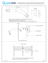
9. Temporarily t the rigid riser pipe and
horizontal arm and wall bracket to
the shower control outlet and mark
the position of the wall bracket. Use
a spirit level to ensure the pipe is
vertical.
Note that the horizontal arm can be
shortened if required. De-burr the
pipe ends before making the nal
connection.
10. Fix the wall bracket, rigid riser
pipe and hand-tighten the three
compression ttings on the shower
control outlet and horizontal arm.
Apply a further 3/4 to 1 1/4 turns
to each compression nut, with a
spanner, to effect a seal.
Note! Care must be taken when
tightening compression nuts so
that you do not damage the plated
surfaces.
11. Thoroughly ush the outlet pipework
before connecting the shower head.
Slide the compression nut over
the horizontal arm and make the
connection to the shower head.
Olive
Horizontal Arm
Compression
Nut
Rigid Riser Pipe
Shower Head
Fixing
Screws
Wall Plugs

14
COMMISSIONING
Maximum temperature setting
This thermostatic shower control has been fully performance tested and the maximum
temperature has been pre-set to approximately 42°C under ideal installation
conditions at the factory. Site conditions and personal preference may dictate that
the maximum temperature has to be reset.
To reset the maximum temperature ensure that an adequate supply of hot water is
available at a temperature at least 10°C in excess of that required from the shower
control. Turn the lever fully anti-clockwise then check the temperature at the discharge
point, (allowing sufcient time for hot water to reach the hot inlet of the shower
control). If the temperature is correct, turn the lever fully clockwise to the off position
as no further adjustment is necessary.
If the maximum temperature achieved at the discharge point is unsatisfactory then
adjust the maximum temperature as follows:
1. Before making any adjustments ensure
that upon installation the correct ow
regulators have been fitted. Refer
to the section: 'Installation, Flow
Regulators'.
2. Turn the lever fully anti-clockwise to the
hot position.
3. Carefully unscrew the grub screw cover
and remove.
4. Use the 2.5 mm hexagon wrench
(supplied) to loosen the grubscrew.
5. Remove the lever housing from the
hexagon spindle.
6. Locate the 2.5 mm A/F hexagon wrench
(supplied) in the grub screw.
7. Adjust as follows:
Warmer - Turn anti-clockwise
Cooler - Turn clockwise.
8. Ret the lever assembly in reverse order
and turn the shower control off.
Grub
Screw
Hexagon
Spindle
Lever
Grub Screw Cover
Cooler
Warmer

15
OPERATION
This thermostatic shower control has a single sequential lever. The shower control
is turned on by turning the control lever anti-clockwise. The shower control is
turned off by turning the control lever clockwise. When the control lever is turned
on (anti-clockwise) the sequence is:
Cold water Warm water Pre-set maximum temperature.
Initial anti-clockwise movement turns the water on at full ow of cold water, further
anti-clockwise movement increases the temperature. The ow rate is determined by
the supply pressures at the inlets of the shower control, or by the effective output
power of the heater appliance. Flow rates for gas water heaters and combination
boilers can vary typically between 8 L/min (winter) and 15 L/min (summer).
Warning! For safety reasons this product incorporates a maximum temperature
setting. This setting must be checked and adjusted as necessary to suit both site
conditions and user’s comfort. Refer to the section: 'Commissioning, Maximum
Temperature Setting'.

16
MAINTENANCE
General
Read the section 'Important Safety Information' rst.
Providing the shower control has been correctly installed and is operated in
accordance with the instructions contained in this guide, difculties should not
arise. If any maintenance is required then it must be carried out by a competent
tradesperson for whom the fault diagnosis chart and maintenance instructions
are provided. Before replacing any parts ensure that the underlying cause of the
malfunction has been resolved.
Shower controls are mechanical devices and should be serviced annually depending
on the water conditions. Areas of the country which are affected by hard water should
consider shorter service intervals.
When installed in very hard water areas (above 200 p.p.m. temporary hardness)
your installer may advise the installation of a water treatment device to reduce the
effects of limescale formation.
You may, if you wish, choose to engage the services of a Mira Service Engineer or
Agent, the terms of which are outlined on the back page of this guide.
Cleaning
Many household cleaners contain abrasives and chemical substances, and should
not be used for cleaning plated or plastic ttings. These nishes should be cleaned
with a mild washing up detergent or soap solution, and then wiped dry using a soft
cloth.
Filters
1. Isolate the hot and cold water
supplies and turn on the ow control
to relieve pressure and drain any
residual water.
2. Unscrew the inlet and outlet
connectors.
3. Using a 2.5 mm hexagon wrench,
loosen the grubscrew and remove the
shower control from the backplate.
4. Clean or replace the inlet lters.
5. Re-assembly is the reversal of the
above procedure.
6. Restore the hot and cold water
supplies and check for leaks.
Filter

17
Fault Diagnosis
Malfunction Cause Remedy
Incorrect
temperature at
outlet.
Insufcient hot water.
Flow regulators fitted
incorrectly.
Maximum Temperature
set incorrectly.
Check temperature setting of hot
water system (60°C - 65°C).
Refer to section: 'Installation, Flow
Regulators'.
Refer to section: 'Commissioning,
Maximum Temperature Setting'.
Flow rate too
high.
Flow regulators fitted
incorrectly, or not tted.
Refer to section: 'Installation, Flow
Regulators'.
Flow rate too
low.
Flow regulators fitted
when not required.
Isolating valves not fully
open.
Airlock or partially blocked
pipework.
Blocked shower head.
Blocked Filters.
Refer to section: 'Installation, Flow
Regulators'.
Open isolating valves.
Flush system and if appropriate t
oat type automatic air vent.
Remove and clean.
Clean or replace.
Outlet
temperature
either too hot or
too cold when
turned fully on.
Hot and cold supplies
have been connected in
reverse.
Check connections and if necessary
turn over shower control and swap
outlet tting with blanking plug.
Shower control
cannot be shut
off.
Pipework not flushed
before connecting the
shower control.
Clean shower control and if necessary
replace seals.
Unstable blend
temperature.
Spray plate blocked.
Flow regulators fitted
incorrectly.
Isolating valve partially
closed.
Descale.
Refer to section: 'Installation, Flow
Regulators'.
Open fully.

18
SPARE PARTS
066.19 Regulator Set
100.75 Rigid Riser Set - chrome
100.76 Rigid Riser Set - light golden
122.66 Head Assembly
122.67 Sleeve Assembly
122.68 Seal Pack - components identied 'A'
122.69 Component Pack - light golden - components identied 'B'
122.70 Thermostat
122.71 Lever Assembly - chrome
122.72 Component Pack - chrome - components identied 'C'
122.73 Lever Assembly - light golden
122.74 Indicator Trim - chrome
122.75 Indicator Trim - light golden
349.98 Shower Arm Set - chrome
349.99 Shower Arm Set - light golden
555.91 Outlet Connector Set - chrome
555.92 Outlet Connector Set - light golden
802.38 Elbow Set - chrome
802.39 Elbow Set - light golden
804.08 Rose Set - chrome
804.09 Rose Set - light golden
805.51 Bracket Set, Shower Arm - chrome
805.52 Bracket Set, Shower Arm - light golden

19
805.51
805.52
349.98
349.99
802.38
802.39
100.75
100.76
555.91
555.92
122.71
122.73
122.74
122.75
122.66
122.67
066.19
122.70
A
A
A
A
A
A
A
A
B, C
B, C
B, C
B, C
B, C
B, C
B, C
B, C
A
066.19
802.38
802.39
804.08
804.09
A
A
ACCESSORIES
Shower Seat
White - 2.1536.128
White/Chrome - 2.1536.129
For use in or out of the showering
area. Folds up when not in use.
Maximum User Weight - 127 kg
(20 stone) Note! Must be installed
onto a solid wall.
Wall Mounted Soap Dish
White - 1.1540.278
Chrome - 1.1540.279
Wall mounted for use
anywhere in, or outside the
showering area.
Premium Shower Seat
White/Chrome - 2.1731.001
Grey/Chrome - 2.1731.002
Stylish, slim-line and robust
shower seat for use in or outside
of the shower area. Folds up when
not in use. Maximum User Weight
- 150 kg (23.5 stone) Note! Must
be installed onto a solid wall.

20
Guarantee
Your product has the benefit of our manufacturer’s
guarantee which starts from the date of purchase.
To activate this guarantee, please return your completed
registration card, visit our website or free phone 0800
0731248 within 30 days of purchase (UK only).
Within the guarantee period we will resolve defects in
materials or workmanship, free of charge, by repairing or
replacing parts or product as we may choose.
If you have not previously activated the guarantee, you will
be required to do so prior to the provision of assistance.
If you do not activate your guarantee our Engineer will be
entitled to charge full payment for the visit (Call out fee
plus parts).
This guarantee is in addition to your statutory rights
and is subject to the following conditions:
● The product must be installed and maintained in
accordance with the instructions given in this user
guide.
● Servicing must only be undertaken by us or our
appointed representative. Note! if a service visit
is required the product must be fully installed and
connected to services.
● Repair under this guarantee does not extend the original
expiry date. The guarantee on any replacement parts
or product ends at the original expiry date.
● For shower fi ttings or consumable items we reserve
the right to supply replacement parts only.
The guarantee does not cover:
● Call out charges for non product faults (such as
damage or performance issues arising from incorrect
installation, improper use, lack of maintenance, build up
of limescale, frost damage, corrosion, system debris or
blocked fi lters) or where no fault has been found with
the product.
● Water or electrical supply, waste and isolation issues.
● Compensation for loss of use of the product or
consequential loss of any kind.
● Damage or defects caused if the product is repaired
or modifi ed by persons not authorised by us or our
appointed representative.
● Routine maintenance or replacement parts to comply
with the requirements of the TMV 2 or TMV 3 healthcare
schemes.
What to do if something goes wrong
If your product does not function correctly when you fi rst
use it, contact your installer to check that it is installed
and commissioned in accordance with the instructions in
this manual. Should this not resolve the issue, contact our
Customer Services Team who will offer you or your installer
advice and if applicable arrange for a Service Technician to
call. If the performance of your product declines, check in
this manual to see if simple home maintenance is required.
If you require further assistance call our Customer Services
Team.
Extended Guarantees
A selection of protection plans are available that
enable you to cover repair bills for the life of your policy
(excludes Eire). Ring 01922 471763 for more details.
Helpdesk Service
Our dedicated Customer Services Team is comprehensively
trained and can offer help and advice, spare parts,
accessories or a service visit. We will need you to have your
model name or number, power rating (if applicable) and date
of purchase. As part of our quality and training programme
calls may be recorded or monitored.
Mira Showers Website (www.mirashowers.co.uk)
From our website you can register your guarantee,
download additional user guides, diagnose faults, purchase
our full range of accessories and popular spares, refer to
our FAQ’s and request a service visit.
Spares and Accessories
We maintain extensive stocks of genuine spares and
accessories and aim to provide support throughout the
product’s expected life. Payment can be made by phone
at time of order using most major Credit or Debit cards and
we aim to despatch orders within two working days. Items
purchased from us are guaranteed for 12 months from date
of purchase. For safety reasons spares exposed to mains
voltages should only be fi tted by competent persons.
Returns – items can be returned within one month of date of
purchase, providing that they are in good condition and the
packaging is unopened. Please obtain authorisation from
our Customer Services Team before return. We reserve the
right to apply a 15% restocking charge.
Service / Repairs
We have a nationwide team of Service Technicians who can
carry out all service or repair work to your product within the
guarantee period and beyond. You have the assurance of a
fully trained Mira Te chnician, genuine Mira spare parts and
a 12 month guarantee on any chargeable work done.
Payment should be made directly to the Service Technician
who will accept most major Credit or Debit cards.
To Contact Us
UK
Telephone: 0844 571 5000
www.mirashowers.co.uk
E-mail: [email protected]
Fax: 01242 282595
By Post: Mira Customer Services Dept, Cromwell Road,
Cheltenham, Gloucestershire, GL52 5EP
Eire
Telephone: 01 459 1344
E-mail: [email protected]
Fax: Dublin 01 459 2329
By Post: Modern Plant Ltd (Dublin),
Otter House, Naas Road, Clondalkin, Dublin 22
Mira is a registered trade mark of
Kohler Mira Limited.
The company reserves the right to alter
product specifi cations without notice.
CUSTOMER SERVICE
1078569-W2-B (B80 / B88) (1438) © Kohler Mira Limited, October 2010
/