Martin M2GO Installation guide

Type
Installation guide

This manual is also suitable for

M1™, M2GO™ and M2PC™
MIDI PCB Module Installation Guide
SMPTE PCB Module Installation Guide
Author Part number Date
Matthias Hinrichs/Chris Foblets 35000620-B 20.06.2012
Martin Professional R&D
Martin M1 M2GO SMPTE-MIDI PCB Installation Guide Page 2
This guide is also available for download as a color PDF on the M1, M2GO and M2PC
Product Support pages under After Sales
Æ
Controller Support at the Martin website –
www.martin.com
1. Introduction
The MIDI PCB is an optional accessory that can be installed in any Martin™ M1, M2GO or
M2PC console.
A combined data and power connection for the PCB is installed in every M1, M2GO and
M2PC at the factory and the installation of the PCB will take about 15 minutes.
Before installation, save all important data from the controller to an external USB flash
drive.
Have the following tools ready:
Torx T20 driver
Torx T10 driver
3mm Hex driver (Only M1 controller)
Warning! Disconnect all cables from the controller, especially the IEC power input
cable.
Before starting work on the M1, M2GO or M2PC, discharge yourself against a grounded
metal surface to prevent static electricity from damaging a component inside the controller.
We recommend that you wear an anti-static bracelet and/or work at an anti-static
workstation.
Martin Professional R&D
Martin M1 M2GO SMPTE-MIDI PCB Installation Guide Page 3
2. Installing the MIDI PCB in an M1 controller
2.1 Removing the top plate
1. Place the M1 on a hard and perfectly flat surface.
2. Remove six Torx T20 screws from the front and back of the M1:
Two T20 screws below the hand rest on the front
Four T20 screws on the back
3. Loosen four 3 mm Hex screws from the top plate. They are captive and stay attached.
Do not try to unscrew them completely from the plate.
Four 3 mm Hex screws
Martin Professional R&D
Martin M1 M2GO SMPTE-MIDI PCB Installation Guide Page 4
4. Carefully angle the screen backwards until it is parallel to the surface the M1 is placed
on.
Tilt the touch screen back
5. Lift the top plate out of the controller by about 20 mm until the supporting metal
structure is free. Move it towards the front of the controller slowly until it clears the
touchscreen housing.
Lift first, then pull forward
Martin Professional R&D
Martin M1 M2GO SMPTE-MIDI PCB Installation Guide Page 5
6. Lift the top plate forward as if you were opening a hinged lid until it is at about 90° to
the work surface.
7. On the back of the top plate are a large data connector and a small power connector.
Unclip the data connector and remove it carefully. Release the power connector by
pressing on its latch, then disconnect it.
Data and power connectors under the front plate.
8. Remove the top plate from the controller and place it securely away from the desk. Do
not rest it on its exposed back. Ideally, lean it against a wall or lay it on a flat surface
with soft padding material such as a protective mat or blanket underneath it to avoid
damage.
Martin Professional R&D
Martin M1 M2GO SMPTE-MIDI PCB Installation Guide Page 6
2.2 Removing the blanking plate
1. Locate the MIDI blanking plate to the left of the power supply.
2. To enable easier access, disconnect both power connections from the fuse PCB
attached to the power supply chassis:
Main Power cables and fuse PCB
3. Using a Torx T10 driver, remove all 4 screws from the MIDI blanking plate and remove
the plate from the M1. Do not lose the screws and washers, as they will be needed in a
moment to secure the new PCB in its place.
Four T10 screws and washers
4. Store the blanking plate in a safe, dry place in case you ever wish to remove the MIDI
PCB from the M1 again in future.
Martin Professional R&D
Martin M1 M2GO SMPTE-MIDI PCB Installation Guide Page 7
2.3 Installing the MIDI PCB
1. Remove the MIDI PCB from its anti-static bag and hold it over its position with the MIDI
connectors facing towards the back of the M1.
2. Before you fasten the PCB in place, connect the RJ45 cable with the “USB MIDI” label
to the connector on the PCB. No other connections are needed.
Data and Power RJ45 “USB MIDI” connector
3. Fasten the PCB in place with the 4 screws and washers that you removed from the
MIDI blanking plate, applying a torque of approximately 1.5 Nm.
4. Reconnect the two power cables next to the PSU and ensure that they click into place:
MIDI PCB in place and power cables connected
Martin Professional R&D
Martin M1 M2GO SMPTE-MIDI PCB Installation Guide Page 8
2.4 Reassembly
The M1 must be standing on a hard and perfectly flat surface during reassembly. If it is
not, the chassis may be twisted which will cause damage.
1. Place the top panel in front of the M1 chassis.
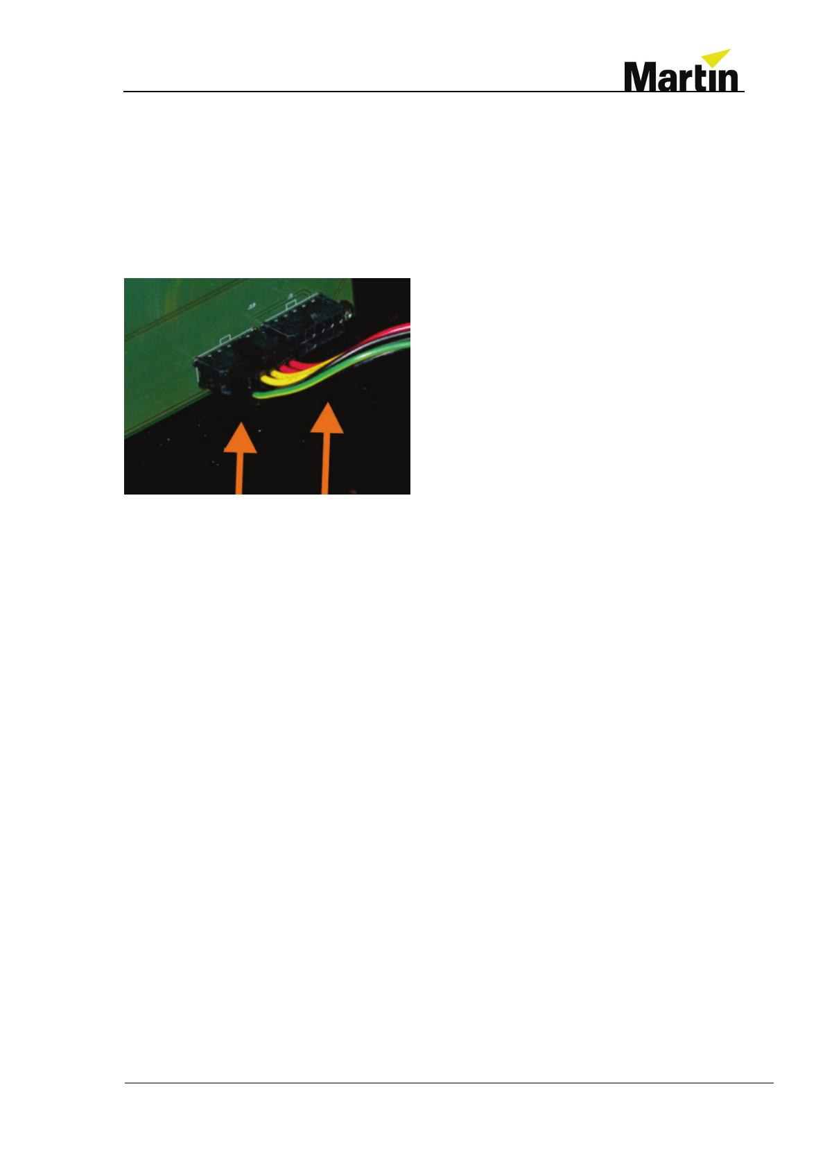
2. Reconnect the data and power connections. Secure the data connection with the
spring clips provided. Two identical power connectors are provided on the front panel
right next to each other, it does not matter which one of them is used:
3. Guide the top plate back into its position carefully underneath the screen housing and
lower it into the chassis. If it is difficult to fit at the back, hold it with one hand and hold
the screen housing with the other. A slight pull backwards on the screen housing will
open more room for the top plate to settle into place.
4. Once the top plate is correctly in position, place the six Torx screws around the front
and the back into their holes. Tighten them down lightly at first. Once they are in place,
tighten them in the following order:
Front left, Front right, Back left, Back right, Monitor left, Monitor right.
5. Now check that the M1 is level by pushing on the corners to test for any wobble. If any
of the feet do not rest on the work surface, loosen the screws and adjust the plate and
chassis, then repeat the above process.
6. Next, tighten the four 3 mm Hex screws on the top plate, tightening gradually in a cross
pattern:
Bottom left, Top Right, Top Left, Bottom Right
7. Reconnect all cables and power the M1 on.
Martin Professional R&D
Martin M1 M2GO SMPTE-MIDI PCB Installation Guide Page 9
2.5 Test
1. When the LOAD SHOW screen is displayed, find the “More” button at the bottom of the
screen and expand it.
2. Find the “Tools - Diagnostic” menu and start the “Console tester”
3. Connect a MIDI cable from the IN port to the OUT port on the back of the M1 to form a
loop.
4. Find the “Timecode tester”:
5. Select “Loop”.
6. Check that:
‘Note OUT’ shows increments
09 90 xx 40 appears in the ‘Event IN’ box ( xx is incrementing hexadecimal
number )
7. If this check is successful, close the Console Tester to stop the test.
The MIDI PCB installation is now complete.
Martin Professional R&D
Martin M1 M2GO SMPTE-MIDI PCB Installation Guide Page 10
2.6 Troubleshooting
If the Timecode Tester does not perform as described above:
Check that the MIDI cable is correctly connected to create a loop between IN and
OUT ports.
Disconnect the M1 from power and check all the connections made during
installation.
Martin Professional R&D
Martin M1 M2GO SMPTE-MIDI PCB Installation Guide Page 11
3. Installing the MIDI PCB in an M2GO/M2PC controller
3.1 Removing the top plate
1. Place the M2GO/M2PC on a hard and perfectly flat surface.
2. Remove eight Torx T20 screws from the front and back of the M2GO/M2PC:
Four T20 screws on the front
Four T20 screws on the back
3. Loosen two T20 screws that hold the power plate and desk lamp plate. Do not unscrew
them completely from the plate.
Two T20 screws
Martin Professional R&D
Martin M1 M2GO SMPTE-MIDI PCB Installation Guide Page 12
4. Lift the top plate out of the controller and place it upside down behind the controller
base. Do not disconnect any cabling.
Lift first, then place upside down behind base
Martin Professional R&D
Martin M1 M2GO SMPTE-MIDI PCB Installation Guide Page 13
3.2 Removing the blanking plate
5. Locate the MIDI blanking plate on the right of the controller base.
Midi blanking plate
6. Using a Torx T10 driver, remove all 4 screws from the MIDI blanking plate and remove
the plate from the M2GO/M2PC. Do not lose the screws, cable tie and washers, as
they will be needed in a moment to secure the new PCB in place.
Four T10 screws, cable tie and washers
7. Store the blanking plate in a safe, dry place in case you ever wish to remove the MIDI
PCB from the M2GO/M2PC again in future.
Martin Professional R&D
Martin M1 M2GO SMPTE-MIDI PCB Installation Guide Page 14
3.3 Installing the MIDI PCB
8. Remove the MIDI PCB from its anti-static bag and hold it over its position with the MIDI
connectors facing towards the right of the M2GO/M2PC.
9. Fasten the PCB in place with the 4 screws, cable tie and washers you removed from
the MIDI blanking plate, applying a torque of approximately 1.5 Nm.
Four T10 screws, cable tie and washers
10. Connect the RJ45 cable to the connector on the PCB. No other connections are
needed.
Data and Power RJ45 connector
Martin Professional R&D
Martin M1 M2GO SMPTE-MIDI PCB Installation Guide Page 15
3.4 Reassembly
The M2GO/M2PC must be standing on a hard and perfectly flat surface during
reassembly. If it is not, the chassis may be twisted which will cause damage.
11. Place the top panel on top of the M2GO/M2PC chassis.
12. Lower it into the chassis and watch carefully that the power connector plate and the
desk lamp connector plate are behind the bottom chassis metal plate.
13. Once the top plate is correctly in position, place the eight Torx screws around the front
and the back into their holes. Tighten them down lightly at first. Once they are in place,
tighten them.
14. Tighten the two Torx screws on the power connector plate and the desk lamp
connector plate.
15. Reconnect all cables and power the M2GO/M2PC on.
Martin Professional R&D
Martin M1 M2GO SMPTE-MIDI PCB Installation Guide Page 16
3.5 Test
16. When the LOAD SHOW screen is displayed, find the “More” button at the bottom of the
screen and expand it.
17. Find the “Tools, Diagnostic” menu and start the “Console tester”
18. Connect a MIDI cable from the IN port to the OUT port on the right of the M2GO/M2PC
to form a loop.
19. Find the “Timecode tester”:
20. Select “Loop”.
21. Check that:
‘Note OUT’ shows increments
09 90 xx 40 appears in the ‘Event IN’ box ( xx is incrementing hexadecimal
number )
22. If this check is successful, close the Console Tester to stop the test.
The MIDI PCB installation is now complete.
Martin Professional R&D
Martin M1 M2GO SMPTE-MIDI PCB Installation Guide Page 17
3.6 Troubleshooting
If the Timecode Tester does not perform as described above:
Check that the MIDI cable is correctly connected to create a loop between IN and
OUT ports.
Disconnect the M2GO/M2PC from power and check all the connections made
during installation.
Martin Professional R&D
Martin M1 M2GO SMPTE-MIDI PCB Installation Guide Page 18
4. Installing the SMPTE PCB in an M2GO/M2PC controller
4.1 Removing the top plate
1. Place the M2GO/M2PC on a hard and perfectly flat surface.
2. Remove eight Torx T20 screws from the front and back of the M2GO/M2PC:
Four T20 screws on the front
Four T20 screws on the back
3. Loosen two T20 screws that hold the power plate and desk lamp plate. Do not unscrew
them completely from the plate.
Two T20 screws
Martin Professional R&D
Martin M1 M2GO SMPTE-MIDI PCB Installation Guide Page 19
4. Lift the top plate out of the controller and place it upside down behind the controller
bottom. Do not disconnect any cabling.
Lift first, then place it upside down behind
Martin Professional R&D
Martin M1 M2GO SMPTE-MIDI PCB Installation Guide Page 20
4.2 Removing the blanking plate
5. Locate the SMPTE blanking plate to the right of the controller bottom.
SMPTE blanking plate
6. Using a Torx T10 driver, remove all 4 screws from the SMPTE blanking plate and
remove the plate from the M2GO/M2PC.
7. Store the blanking plate in a safe, dry place in case you ever wish to remove the
SMPTE PCB from the M2GO/M2PC again in future.
  • Page 1 1
  • Page 2 2
  • Page 3 3
  • Page 4 4
  • Page 5 5
  • Page 6 6
  • Page 7 7
  • Page 8 8
  • Page 9 9
  • Page 10 10
  • Page 11 11
  • Page 12 12
  • Page 13 13
  • Page 14 14
  • Page 15 15
  • Page 16 16
  • Page 17 17
  • Page 18 18
  • Page 19 19
  • Page 20 20
  • Page 21 21
  • Page 22 22
  • Page 23 23
  • Page 24 24

Martin M2GO Installation guide

Type
Installation guide
This manual is also suitable for

Ask a question and I''ll find the answer in the document

Finding information in a document is now easier with AI