Page is loading ...

FEATURES
♦ Audible click and/or impulse when torque setting is
reached.
♦ +/- 4% clockwise accuracy between 20% and 100% of
range. Complies with:
− American Standard ANSI/ASME B107.14M
−
International Standard ISO 6789
♦ Large easy to read torque scale.
♦ Ball bearing mechanism provides extended calibration
accuracy.
♦ Anodized aluminum handle with no-slip diamond knurl.
♦ Detent style adjustment locking prevents accidental
change of torque setting.
♦ Chrome plated, hardened steel body.
♦ Factory calibration tape supplied with each tool.
♦ Packaged in protective blow molded storage case.
SUGGESTIONS
Proper use of this professional torque wrench will give you
complete satisfaction in its performance and reliability.
Following are some helpful tips:
1. Accuracy is assured by gripping the wrench properly.
Grasp the GRIP, not the SHAFT, and pull smoothly.
2. Each torque wrench is lubricated before leaving the factory.
If it has not been used for some time, it should be operated
several times to re-distribute the lubricant within the working
mechanism.
3. Never attempt to turn the KNOB when the KNOB is in the
"LOCK" position.
4. Never set for higher or lower torque values than those
indicated on your wrench.
5. For greater accuracy, clean all thread surfaces and remove
any burrs on the fasteners being used.
6. WARNING-never use your torque wrench to apply more
torque than its rated capacity.
7. It is not necessary to return this wrench to its lowest
calibrated value after use unless it is to be stored for an
extended period of time.
DO NOT OVERTORQUE
CERTIFICATION
This torque wrench was calibrated prior to shipment from the
factory within tolerance limits of +/- 4% clockwise (right-handed)
accuracy of upper 80% of range
LIMITED WARRANTY
Until one year from the date of purchase, we will repair any
defect in material or workmanship free of charge. Improper use
of these products, including but not limited to the application of
excessive force, will affect performance and may result in
injury. The warranty does not apply to wrenches which do not
function properly or within specified accuracy because of wear,
improper or unreasonable use, damage not resulting from
defect or malfunction, or which have been altered. Calibration is
warranted for 90 days.
This warranty gives you specific legal rights, and you may also
have other rights which vary from state to state.
For repair or calibration send wrench, postage prepaid, to:
IN THE U.S.A.
Angle Repair & Calibration
175 Angle Drive
Beckley, WV 25801
972-864-6762
IN CANADA
REVISED/PRINTED IN USA APR 2014 FORM CT600-61D
ATD-109
MICROMETER
ADJUSTING
TORQUE
WRENCH
OPERATING
INSTRUCTIONS
ATG Torque Repair
7631 Bath Road
Mississauga, ON L4T3T1
1-866-691-6212

ADJUSTING YOUR MICROMETER TORQUE
WRENCH
Caution – Do not turn the adjusting knob with the
knob in the locked position. Damage to the
locking mechanism may occur.
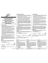
1. The minor scale is
located on the
adjusting knob. One
revolution of the knob
advances the major
scale located in the
grip window by one
increment.
2. To adjust the torque
setting, push the
adjusting knob toward
the grip until it
unlocks and turn it to
the right to increase
the torque setting and
to the left to reduce it.
3. To set 362.5 ft-lbs for
example, turn the
adjusting knob until
the red indicator in
the major scale
window is aligned
with the closest
major lbf-ft increment
at or below the target
torque setting and
the knob is aligned
on zero. Note: Lbf-ft
units are on the right
side of the window
and Nm units are on
the left side.
4. Turn the knob an
additional 5
increments to set it on
12.5 and release it to
lock the torque setting.
The two scales added
together give 362.5 ft-
lbs. For Nm settings
use the lower scale on
the knob.
TORQUE UNIT CONVERSIONS
Torque values can be converted to other units very
easily with simple multiplication.
To convert torque values from one unit to another,
multiply the value of the given torque unit by the
correct conversion factor to get the desired torque
value.
Inch Pounds x .08333 = Foot Pounds
Meter Kilograms f x 7.233 = Foot Pounds
MAJOR SCALE
KNURLED GRIP
SCALE INDEX
MINOR SCALE
ADJUSTING
KNOB
HOW TO APPLY TORQUE
1. This Micrometer Adjustable Torque Wrench
when properly used is designed to provide an
audible signal and/or impulse feel to indicate the
desired torque has been applied. DO NOT
pull
beyond this point.
CAUTION: The audible signal / or impulse
feel is an indicator that the proper torque has
been attained. Over torquing beyond these
signals could cause fastener failure.
ADDITIONALLY: When the wrench is set at
the low end of the torque range, the degree of
signal and impulse will be less than when set at
the high end of the range. Therefore, care
must be taken at the low end of scale to hear
the signal or feel the impulse.
2. To properly apply torque, attach a socket securely
on the torque wrench square drive and position
the socket on the fastener so that tilting will not
occur. Grasp the center of the hand grip and
apply a slow steadily increasing force
perpendicular (90 degrees) to the torque wrench
body and perpendicular to the center line of the
square drive, socket, and fastener.
3. Turn the fastener down with a smooth and even
force applied to the handle of the torque wrench.
As turning resistance increases, pull more slowly.
To assure accuracy, the fastener must be in
motion when the torque measurement is made.
WARNING: Any change from the above
procedure will result in a change of torque
being applied. DO NOT USE universal joints or
universal sockets due to the complexity of
determining the associated error.
4. EXTENSIONS: When necessary to use an
extension that changes the lever length of the
torque wrench, torque being applied will change.
To compute the wrench setting :
L E
Wrench Setting = (Desired Torque x L) / (L + E)
NOTE: Socket extension bars that are axially
in line with the square drive do not cause error
and need no adjustment.

ATD-109
/


