
Henny Penny
Cold Tops
Model CMC/CMR-103
Model CMC/CMR-104
Model CMC/CMR-105
Model CMC/CMR-106
Model CMC/CMR-107
OPERATOR’S MANUAL

Model CMC/CMR-103,104,105,106,107
LIMITED WARRANTY FOR HENNY PENNY APPLIANCES
Subject to the following conditions, Henny Penny Corporation makes the following limited warranties to the
original purchaser only for Henny Penny appliances and replacement parts:
NEW EQUIPMENT: Any part of a new appliance, except lamps and fuses, which proves to be defective
in material or workmanship within two (2) years from date of original installation, will be repaired or replaced
without charge F.O.B. factory, Eaton, Ohio, or F.O.B. authorized distributor. To validate this warranty, the
registration card for the appliance must be mailed to Henny Penny within ten (10) days after installation.
REPLACEMENT PARTS: Any appliance replacement part, except lamps and fuses, which proves to be
defective in material or workmanship within ninety (90) days from date of original installation will be repaired
or replaced without charge F.O.B. factory, Eaton, Ohio, or F.O.B. authorized distributor.
The warranty for new equipment and replacement parts covers only the repair or replacement of the defective
part and does not include any labor charges for the removal and installation of any parts, travel or other expenses
incidental to the repair or replacement of a part.
EXTENDED FRYPOT WARRANTY: Henny Penny will replace any frypot that fails due to manufacturing or
workmanship issues for a period of up to seven (7) years from date of manufacture. This warranty shall not cover
any frypot that fails due to any misuse or abuse, such as heating of the frypot without shortening.
0 TO 3 YEARS: During this time, any frypot that fails due to manufacturing or workmanship is-
sues will be replaced at no charge for parts, labor, or freight. Henny Penny will either install a new
frypot at no cost or provide a new or reconditioned replacement fryer at no cost.
3 TO 7 YEARS: During this time, any frypot that fails due to manufacturing or workmanship is-
sues will be replaced at no charge for the frypot only. Any freight charges and labor costs to install
the new frypot as well as the cost of any other parts replaced, such as insulation, thermal sensors,
high limits, fittings, and hardware, will be the responsibility of the owner.
Any claim must be represented to either Henny Penny or the distributor from whom the appliance was pur-
chased. No allowance will be granted for repairs made by anyone else without Henny Penny’s written consent. If
damage occurs during shipping, notify the sender at once so that a claim may be filed.
THE ABOVE LIMITED WARRANTY SETS FORTH THE SOLE REMEDY AGAINST HENNY PENNY
FOR ANY BREACH OF WARRANTY OR OTHER TERM. BUYER AGREES THAT NO OTHER REMEDY
(INCLUDING CLAIMS FOR ANY INCIDENTAL OR CONSQUENTIAL DAMAGES) SHALL BE AVAIL-
ABLE.
The above limited warranty does not apply (a) to damage resulting from accident, alteration, misuse, or abuse;
(b) if the equipment’s serial number is removed or defaced; or (c) for lamps and fuses. THE ABOVE LIMITED
WARRANTY IS EXPRESSLY IN LIEU OF ALL OTHER WARRANTIES, EXPRESS OR IMPLIED, INCLUD-
ING MERCHANTABILITY AND FITNESS, AND ALL OTHER WARRANTIES ARE EXCLUDED. HENNY
PENNY NEITHER ASSUMES NOR AUTHORIZES ANY PERSON TO ASSUME FOR IT ANY OTHER OB-
LIGATION OR LIABILITY.
FM01-878-C
Revised 02-09-06

Model CMC/CMR-103,104,105,106,107
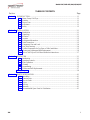
TABLE OF CONTENTS
Section Page
Section 1. INTRODUCTION ...................................................................................................................1-1
1-1. Henny Penny Cold Tops ..............................................................................................1-1
1-2. Features ....................................................................................................................... 1-1
1-3. Proper Care .................................................................................................................1-1
1-4. Assistance.................................................................................................................... 1-1
1-5. Safety........................................................................................................................... 1-2
Section 2. INSTALLATION......................................................................................................................2-1
2-1. Introduction ..................................................................................................................2-1
2-2. Unpacking .................................................................................................................... 2-1
2-3. Electrical ......................................................................................................................2-2
2-4. Location .......................................................................................................................2-3
2-5. Refrigerant Information ............................................................................................... 2-3
2-6. Drain Connection .........................................................................................................2-3
2-7. Compressor Size and Load ..........................................................................................2-4
2-8. Foot Print Drawing ...................................................................................................... 2-4
2-9. Cut Out Dimensions for Dry Base or Table Installation ..............................................2-5
2-10. Flourescent Lighting and Bulb Replacement ............................................................... 2-6
2-11. Hot or Cold Top on a Cold Base Installation Instructions ............................................ 2-7
Section 3. OPERATION............................................................................................................................3-1
3-1. Introduction ..................................................................................................................3-1
3-2. Operating Controls .......................................................................................................3-1
3-3. Basic Operation ...........................................................................................................3-3
3-4. Cleaning .......................................................................................................................3-3
3-5. Programming................................................................................................................3-5
3-6. Fluorescent Bulb Replacement ....................................................................................3-7
Wiring Diagram .........................................................................................................................3-8
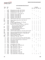
Section 4. PARTS INFORMATION .........................................................................................................4-1
4-1. Introdution....................................................................................................................4-1
4-2. Genuine Parts ..............................................................................................................4-1
4-3. How to Order ..............................................................................................................4-1
4-4. Prices...........................................................................................................................4-1
4-5. Delivery .......................................................................................................................4-1
4-6. Warranty ......................................................................................................................4-1
4-7. Recommended Spare Parts for Distributors................................................................4-1
206 i

Model CMC/CMR-103,104,105,106,107
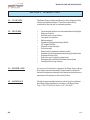
1-1. COLD TOPS The Henny Penny cold tops are full service units, designed to hold
chilled or refrigerated products. The units are electronically
controlled for easy use and for consistent operation.
1-2. FEATURES • Can be matched with hot or cold merchandisers in all lengths
• Electronic Controls
• Stackable units on top of bases
• Low speed air circulation
• Easily maintained
• Fluorescent lighting with electronic ballast
(CE-magnetic ballast)
• Mirrored or clear side glass
• Full service units
• Remote or self-contained condenser models
• Insulated-well with high pressure injected polyurethane foam
• Automatic defrost cycles
• Fold-down wood or plastic cutting board
• Sliding rear doors with double thermal mirrored glass
• Front glass lifts for easy cleaning
1-3. PROPER CARE As in any unit of food service equipment, the Henny Penny cold top
does require care and maintenance. Requirements for the mainte
nance and cleaning are contained in this manual and must become a
regular part of the operation of the unit at all times.
1-4. ASSISTANCE Should you require outside assistance, just call your local indepen-
dent Henny Penny distributor in your area, or call Henny Penny
Corp. 1-800-417-8405 toll free or 1-937-456-8405.
503 1-1
SECTION 1. INTRODUCTION

Model CMC/CMR-103,104,105,106,107
1-5. SAFETY The Henny Penny cold tops have many safety features
incorporated. However, the only way to ensure a safe operation
is to fully understand the proper installation, operation, and
maintenance procedures. The instructions in this manual have
been prepared to aid you in learning the proper procedures.
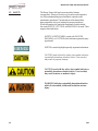
Where information is of particular importance or safety related,
the words NOTICE, CAUTION, and WARNING, are used. Their
usage is described below.
SAFETY ALERT SYMBOL is used with DANGER,
WARNING, or CAUTION which indicates a personal injury
type hazard.
NOTICE is used to highlight especially important information.
CAUTION used without the safety alert symbol indicates
a potentially hazardous situation which, if not avoided,
may result in property damage.
CAUTION used with the safety alert symbol indicates a
potentially hazardous situation which, if not avoided,
may result in minor or moderate injury.
WARNING indicates a potentially hazardous situation
which, if not avoided, could result in death or serious
injury.
1-2 303

Model CMC/CMR-103,104,105,106,107
2-1. INTRODUCTION This section provides the installation for Henny Penny cold tops.
Installation of this unit should be performed only by a
qualified service technician.
Do not puncture the unit with any objects such as
drills or screws, or component damage or electrical
shock could result.
2-2. UNPACKING The Henny Penny Cold Top has been tested, inspected, and
expertly packed to insure arrival at its destination in the best
possible condition. The grids, side glass, and sliding thermal doors
are packed separately inside the unit. The cabinet rests on a
wooden skid and is then packed inside a heavy cardboard carton
with sufficient padding to withstand normal shipping treatment.
To avoid damage to the components, do not lay the unit
on its side. If the unit has been on its side, the unit must
be in an upright position for at least 4 hours before power
is applied to the unit.
Check all components, for signs of being loose or dam-
aged, and make sure the system has refrigerant.
When moving the cold top be careful not to damage the
refrigerent circuit.
Any shipping damage should be noted in the presence
of the delivery agent and signed prior to his or her
departure.
To remove the Henny Penny cold top from the carton:
1. Carefully cut banding straps.
2. Lift the carton off the unit.
3. Remove bolts securing the cold top to the skid and lift the
unit off the skid.
303 2-1
SECTION 2. INSTALLATION

Model CMC/CMR-103,104,105,106,107
2-2. UNPACKING
Take care when moving the fryer to prevent personal
injury or damage to the refrigeration system. The
CMC-107s weigh over 700 lbs. (318 kg).
4. Peel off any protective covering from exterior of the cabinet.
5. Install the grids into unit.
6. Unpack sliding thermal doors and side glass. Install on rear
and side of unit.
7. Your cold top is now ready for operation.
2-3. ELECTRICAL The Cold Top is available as a 120 VAC, 60 Hz. or 230VAC,
50 Hz., single phase unit, both for domestic and international use.
The data plate, located beside the power cord, specifies the correct
electrical supply. The Cold Tops are shipped with cord and plug,
and requires a grounded receptacle with a separate electrical line
protected by a fuse or circuit breaker of the proper rating. Position
the unit so the power cord receptacle is accessible.
To avoid electrical shock, this appliance must be
equipped with an external circuit breaker which will
disconnect all ungrounded (unearthed) conductors.
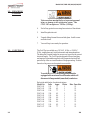
Refer to the table below for electrical ratings:
Model No. Volts Amps Phase Max. Fuse Size
CMC-103 120 7.7 1 15
CMC-103 230 4.5 1 15
CMC-104 120 7.7 1 15
CMC-104 230 4.5 1 15
CMC-105 120 8.6 1 15
CMC-105 230 6.0 1 15
CMC-106 120 8.6 1 15
CMC-106 230 6.0 1 15
CMC-107 120 9.5 1 15
CMC-107 230 7.7 1 15
(Continued)
2-2 303

Model CMC/CMR-103,104,105,106,107
303 2-3
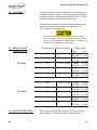
2-5. REFRIGERANT Design Pressure
INFORMATION High Low
CMC-103 R22 1.5 lbs (0.680 kg) 440psig 162 psig
(30.3 bar) (11.2 bar)
CMC-104 R22 1.5 lbs (0.680 kg) 440psig 162 psig
(30.3 bar) (11.2 bar)
UL Specs CMC-105 R22 2.5 lbs (1.134 kg) 440psig 162 psig
(30.3 bar) (11.2 bar)
CMC-106 R22 2.5 lbs (1.134 kg) 440psig 162 psig
(30.3 bar) (11.2 bar)
CMC-107 R22 2.5 lbs (1.134 kg) 440psig 162 psig
(30.3 bar) (11.2 bar)
CMC-103 R134A 1.65 lbs (0.750 kg) 440psig 162 psig
(30.3 bar) (11.2 bar)
CMC-104 R134A 1.87 lbs (0.850 kg) 440psig 162 psig
(30.3 bar) (11.2 bar)
CE Specs CMC-105 R134A 2.65 lbs (1.200 kg) 440psig 162 psig
(30.3 bar) (11.2 bar)
CMC-106 R134A 3.09 lbs (1.400 kg) 440psig 162 psig
(30.3 bar) (11.2 bar)
CMC-107 R134A 3.53 lbs (1.600 kg) 440psig 162 psig
(30.3 bar) (11.2 bar)
2-6. DRAIN CONNECTION The cold tops-remote (CMRs), requires 1-1/2 inch (38.1 mm)
drain connection. CMCs do not require a plumbed drain.
Refrigerant Type Amount of Refrig.
2-4. LOCATION Place the cold tops in an area where product can be loaded and
unloaded without interruption. For proper operation, level the unit
by adjusting the bolts under the base, and leave 3 feet (91.44 cm)
clearance behind the unit for ventilation and service.
For maximum efficiency, units should be operated in an air-condi-
tioned environment, with maximum air temperature of 75° F
(24° C), and 55% relative humidity.
Wait at least 4 hours before plugging the unit into an
electrical supply. The gases and oils in the refrigeration
system needs to settle before operating the compressor, or
damage to the compressor could result.

Model CMC/CMR-103,104,105,106,107
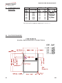
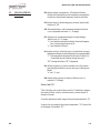
2-8. FOOT PRINT DRAWING
CMR MODELS
DRAIN& REFRIGERATION CONNECTIONS
2-4 303
2-7. COMPRESSOR SIZE
AND LOAD
Model CMC Motor HP CMR Motor HP
CMC/ BTU Load UL CE UL CE
CMR R-22 R-134a R-22 R-134a
103 2860 1/4 1/3 Remote
104 2860 1/4 1/3 Compressor
105 2830 1/3 1/2 Supplied
106 2830 1/3 1/2 By Other
107 3840 1/2 1/2
BTU load sized at evaporator temperature + 20 F or -6 C.

Model CMC/CMR-103,104,105,106,107
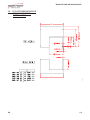
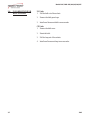
2-9. CUT OUT DIMENSIONS FOR
DRY BASE OR TABLE
INSTALLATION
303 2-5

Model CMC/CMR-103,104,105,106,107
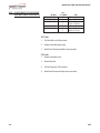
2-10. FLOURESCENT LIGHTING No.
AND BULB REPLACEMENT Model of Lights Size
CMR/CMC-103 1 36 in. (.914 m)
CMR/CMC-104 1 48 in. (1.22 m)
CMR/CMC-105 1 24 in. (.610 m)
1 36 in. (.914 m)
CMR/CMC-106 2 36 in. (.914 m)
CMR/CMC-107 1 36 in. (.914 m)
1 48 in. (1.22 m)
UL Units
1. Pull the bulb out of the sockets.
2. Remove the bulb guard caps.
3. Install new fluorescent bulb in reverse order.
CE Units
1. Remove the bulb cover.
2. Rotate the bulb.
3. Pull the lamp out of the sockets.
4. Install new fluorescent lamp in reverse order.
2-6 403

Model CMC/CMR-103,104,105,106,107
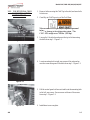
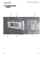
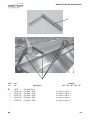
2-11. COLD TOP ON A COLD
BASE INSTALLATION
INSTRUCTIONS
1. Remove bolts securing the Cold Top to the skid, and save bolts
for later use.
2. Carefully set Cold Top on top of the Cold Base.
Take care when moving the fryer to prevent personal
injury
or damage to the refrigeration system. The
CMC-107s weigh over 700 lbs. (318 kg).
3. Line up the 2 front holes and secure the top to the base using
the bolts from step 1. Figure 2-1.
4. Locate mounting hole in right, rear corner of the units and se-
cure the corner using one of the bolts from step 1. Figure 2-2.
5. Pull the control panel out from unit and locate the mounting hole
in the left, rear corner. Secure corner with one of the screws
from step 1. Figure 2-3.
6. Installation is now complete.
Figure 2-1
Figure 2-2
Figure 2-3
403 2-7

Model CMC/CMR-103,104,105,106,107
3-1. INTRODUCTION This section provides explanations of all controls, along
with operating procedures and daily maintenance. Read the
Introduction, Installation and Opeation Sections before
operating the unit.
Wait at least 4 hours before plugging the unit into an
electrical supply. The gases and oils in the refrigeration
system needs to settle before operating the compressor, or
damage to the compressor could result.
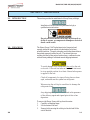
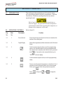
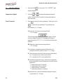
3-2. OPERATING CONTROLS Refer to figure 3-1.
Fig. Item Description Function
No. No.
3-1 1 Power Switch Turns electrical power off and on to the unit; located on the
bottom of the control panel
3-1 2 Digital Display Shows the temperatures and the information in the Technical
Mode
3-1 3 Used to increase setpoint values, as well as programming
values; also, automatic defrost cycles are programmed in
the controls, but to manually start a defrost cycle, press and
hold for 3 seconds to start a manual defrost cycle;
“DEF/SET’ shows in display
3-1 4 Used to decrease setpoint values, as well as programming
values
3-1 5 Press to view the setpoint temperature, or hold it for it for 4
seconds to enter the program mode; once in the Program
Mode, press to view other parameter setpoints;
Press , along with and to change the
parameters
SECTION 3. OPERATION
3-1 303

Model CMC/CMR-103,104,105,106,107
Figure 3-1
3 2 1
4 5
303 3-2
3-2. OPERATING CONTROLS
(Continued)

Model CMC/CMR-103,104,105,106,107
3-3. BASIC OPERATION 1. Turn power switch to ON position.
2. Wait for temperature to reach operating temperature,
34 to 38° F (1.1 to 3.3° C).
3. Place chilled product into case.
Do not block the air return and air discharge vents with
product. Product temperatures may become unsafe,
and increase operating costs.
Do not use mechanical devices or other means to quicken
the defrosting process, other than those recommended by
the manufacturer, or damage to the unit could result.
Do not use electrical appliances inside the food storage
areas of the unit, unless they are of the type recommended
by the manufacturer, or damage to the unit could result.
3-4. CLEANING Weekly:
1. Remove all electrical power supplied to the unit by unplug-
ging the power cord from the wall, or by turning off the
wall circuit breaker.
2. Clean interior and exterior surfaces with a soft cloth, soap and
water.
Do not use steel wool, other abrasive cleaners or
cleaners/sanitizers containing chlorine, bromine, iodine
or ammonia chemicals, as these will deteriorate the
stainless steel, and glass material, and shorten the life of
the unit.
Do not use a water jet (pressure sprayer) to clean the
unit, or component failure could result.
3. Clean around the electronic controls with a soft, damp cloth.
4. Reconnect the electrical power, and unit is now ready for
operation.
3-3 303

Model CMC/CMR-103,104,105,106,107
3-4. CLEANING Every 3 Months:
(Continued) 1. Remove all electrical power supplied to the unit by unplugging
the power cord from the wall, or by turning off the wall circuit
breaker.
2. Remove all product from the unit.
3. Remove the riser and trays from the unit and clean with
soap and water at a sink.
4. Clean interior surfaces with a soft cloth, soap and water.
Do not use steel wool, other abrasive cleaners or
cleaners/sanitizers containing chlorine, bromine, iodine
or ammonia chemicals, as these will deteriorate the
stainless steel, and glass material, and shorten the life of
the unit.
Do not use a water jet (pressure sprayer) to clean the
unit, or component failure could result.
5. Clean around light fixtures with a soft, damp cloth.
6. Reconnect the electrical power, and unit is now ready for
operation.
If the power cord is damaged, have a qualified service
technician replace it to prevent electrical shock or
property damage.
303 3-4

Model CMC/CMR-103,104,105,106,107
3-5. PROGRAMMING 1. Press and hold for 4 seconds. The “DEF/SET” light
flashes in display.
Temperature Setpoint 2. Press the or to change the temperature setpoint,
within 5 seconds. After 5 seconds, the last entered setpoint
stays in memory.
Other Parameters 3. Press to access the other parameters. Each press of the
accesses the next parameter. The parameters are:
d: differential (-15...15 range)
LS: lower set; lower user-access setpoint limit
(-55...99 range)
The units are programmed to defrost 3 times a day, at 8 hour
intervals, lasting 30 minutes. Do not program the setpoint
temperature below 33° F (1° C), or ice build-up will decrease
efficiency.
HS: higher set; upper user-access setpoint limit
(-55...99 range)
CA: calibration; temperature readout offset to allow for
possible error due to probe location (-15...15 range)
rP: relay protection; select relay status in case of probe defect.
“on” = compressor on in case of probe defect.
“of” = compressor off in case of probe defect
PS: protection system-short cycle; select type of compressor
protection desired (the actual time delay is set with the next
parameter):
“0”=delay before start - in seconds;
“1”=delay before start - in minutes;
“2”=delay after stop - in minutes;
“3”=delay between starts - in minutes
Pt: protection time; select the time delay setting for compres-
sor protection. (0...31 range)
3-5 303

Model CMC/CMR-103,104,105,106,107
3-5. PROGRAMMING dS: defrost system (computation); dF=digifrost Feature;
Continued defrost start time based on total compressor running time
rt=real time; defrost start frequency, based on real time
dI: defrost interval; defrost frequency in hours, based on the
selection of “dS”
dE: defrost endurance; total (maximum) length of a defrost
cycle, expressed in minutes. (1...99 range)
dL: display lock; temperature display is locked during a
defrost cycle (0...31 range)
“n”=no (readout continues to display the actual tempera-
ture, even during a defrost cycle
“y”=yes (readout is locked)
dr: display read-out; select the type of visualization in case of
temperature display lock during defrost (see prameter dL);
“C”=the temperature displayed at the start of a defrost is
locked and does not change during this cycle;
“dF”=during the defrost “dF” is displayed.
do: defrost at power on; selects whether or not, the system
goes through the defrost cycle at start-up (or after power
failure)
“n”=no; “y”=yes
dd: defrost delay at power on; delay of defrost cycle, in
minutes (0...99 range)
Error Code “E1”
This is the only error code in these controls. It indicates a tempera-
ture sensor failure, such as, a shorted sensor, a sensor break, or
absence of sensor.
It can also indicate an under-range in the system temperature (-55).
In case of an over-range in the system temperature, “99” shows first
in the display, followed by “E1”.
303 3-6

Model CMC/CMR-103,104,105,106,107
3-6. FLUORESCENT BULB UL Units
REPLACEMENT 1. Pull the bulb out of the sockets.
2. Remove the bulb guard caps.
3. Install new fluorescent bulb in reverse order.
CE Units
1. Remove the bulb cover.
2. Rotate the bulb.
3. Pull the lamp out of the sockets.
4. Install new fluorescent lamp in reverse order.
3-7 1102

Model CMC/CMR-103,104,105,106,107
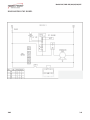
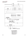
1002 3-8
DIAGRAM FOR CMC MODEL
Page is loading ...
Page is loading ...
Page is loading ...
Page is loading ...
Page is loading ...
Page is loading ...
Page is loading ...
Page is loading ...
-
 1
1
-
 2
2
-
 3
3
-
 4
4
-
 5
5
-
 6
6
-
 7
7
-
 8
8
-
 9
9
-
 10
10
-
 11
11
-
 12
12
-
 13
13
-
 14
14
-
 15
15
-
 16
16
-
 17
17
-
 18
18
-
 19
19
-
 20
20
-
 21
21
-
 22
22
-
 23
23
-
 24
24
-
 25
25
-
 26
26
-
 27
27
-
 28
28


Ask a question and I''ll find the answer in the document
Finding information in a document is now easier with AI
Related papers
-
Henny Penny CMC-106 Operating instructions
-
-
-
Henny Penny HC-941 User manual
-
-
-
-
-
-
Other documents
-
Rittal CMC III DCM Assembly And Operating Instruction
-
BENDIX TCH-030-001 User manual
-
Listen NAVILUTION PA Delivery Demo Quick start guide
-
-
Imada CW-500N Owner's manual
-
Planet UL9200N User manual
-
DataCard 551148-001 Datasheet
-
 Enseo EBS-SP35 User manual
-
Daikin DCC240XXX4BXXX Installation guide
-
Polar Refrigeration G622 User manual
