Page is loading ...

single channel microphone preamplifi er
model
101
all contents © Grace Design/ Lunatec LLC
owner’s manual Rev C
2434 30th street, boulder, CO 80306-0204 USA
tel 303.443.7454 fax 303.444.4634
[email protected]om / www.gracedesign.com

model
101
owner’s manual
page 2
Welcome and thanks for purchasing the Grace
Design model 101 microphone preamplifier and
DI. We build all of our products to be completely
reliable and easy to use, so you can concentrate on
making great recordings, not struggling with com-
plicated equipment or difficult product manuals.
While the model 101 is completely straightfor-
ward to use, we do ask that you spend a little time
familiarizing yourself with this product manual to
help avoid any common user difficulties.
In the event that you do encounter any techni-
cal difficulties with this or any of our products,
feel free to call at 303-443-7454. Our office
hours are 9 to 5, Monday through Friday, MST,
or you may email any technical questions to:
info@gracedesign.com.
Also, please check out our web support page
listed below for the latest Grace Design product
contents
http://www.gracedesign.com/support/support.htm
information, owners manuals and technical docu-
ments. Grace Design has been building audio-
phile-quality products for the recording industry
over 15 years. The technology in the model 101
and all of our products has evolved through a pro-
cess of extensive listening, field-testing and careful
refinement.
Your new model 101 preamplifier represents a re-
markable combination of absolutely pristine audio
performance, robust mechanical construction and
bombproof reliability at a reasonable price.
Regardless of what audio sources you plan to
record, your model 101 will faithfully serve as an
invisible link between your microphone or instru-
ment and recording device.
We sincerely hope our products help you achieve
a new level of excellence in your work!
-The Grace Design Team
Features 3
Front Panel Controls 4
Preamplifier Connections 5
Operation 6
Trim Control 6
Rackmounting 6
Cable Diagrams 7
Specifications 8
Warranty Information 9
Manual Revisions 10

page 3
model
101
owner’s manual
• fast, musical transimpedance amplifier architecture
• fully balanced, transformerless XLR microphone input
• high impedance 1/4 inch instrument DI input
• balanced XLR and 1/4 inch TRS outputs
• gold plated XLR input and output connectors
• 11 position precision silver contact rotary switch gain control
• high quality conductive plastic 10dB output trim control
• 75Hz 12dB/octave transitional Thompson-Butterworth high pass filter
• two color, bi-phase LED peak meter shows signal present and peak
• optional extended gain range input (10-70dB) for ribbon microphones
• 1/2 width 1U chassis / two units fit together in a standard 1U rack tray
• sealed gold contact relay for instrument/mic switching
• high precision active balanced output circuit
• no electrolytic capacitors in the signal path
• ultra clean 48 Volt phantom power
• minimal internal signal wiring
• 5 year warranty on parts and labor
model 101 features

model
101
owner’s manual
page 4
GAIN CONTROL
The gain control has 11 positions and adjusts the voltage
gain on the microphone input from 10dB to 60dB in 5dB
steps. When using the instrument input, the gain range is
–10dB to 40dB in 5dB steps. NOTE: If you ordered the high
gain version of the 101 for use with ribbon microphones,
the gain range of your unit on the microphone input is 20dB
to 70dB in 5dB steps and the gain range of the instrument
input is 0dB to 50dB in 5 dB steps.
TRIM CONTROL
The trim control provides 10dB of continuously variable
output attenuation. In the fully clockwise position the
trim is at unity (no attenuation). In the fully counter-
clockwise position the trim is at -10dB. For reference, the
3 o’clock position is -4dB and the 12 o’clock position is
-8dB. The trim control should be left in the fully clockwise
position during normal recording.
48V PHANTOM POWER
This switch provides 48 volts to power condenser
microphones. The phantom power switch (labeled 48V)
connects the +48V power supply to pins 2 and 3 on the XLR
input connector.
PEAK INDICATOR
The LED peak indicator, which monitors the signal
between the input and output amplifiers, illuminates
the green LED at -14dBu and illuminates the red LED at
+16dB (10dB before clipping). It is located between the
GAIN and TRIM controls.
HIGH PASS FILTER
(labeled HPF) Sometimes referred to as a bass roll-off, the
high pass filter rolls off at 75Hz. This 12dB/octave filter
employs a transitional Thompson-Butterworth response
for the best combination of passband flatness and time
domain response.
POWER SWITCH
The power switch connects power from the DC input
connector to the preamplifier circuitry. When depressed,
the amber POWER LED will illuminate.
1/4 inch TRS instrument HI-Z input
Designed to accommodate a wide variety of high impedance
input sources, making the 101 an excellent choice as a DI box
which will flawlessly preserve the sound of the instrument.
front panel controls

page 5
model
101
owner’s manual
preamplifier connections
OUTPUT CONNECTIONS
are made using the male XLR connector or the ¼” TRS jack. The
XLR connector is wired with pin 2 positive, pin 3 negative and pin
1 ground. The ¼” TRS connector is balanced with the Tip positive,
Ring negative and Sleeve ground. The XLR and TRS outputs can be
used simultaneously.
It is important to note that if either of the outputs are to be used
unbalanced, a modified cable is required (see cable diagram 1
and 2 on page 7). It is not recommended to use an unbalanced ¼”
plug in the TRS output jack, because the sleeve of the unbalanced
plug will short the inverting output amplifier to ground. While this
will not cause damage to the preamplifier, it can cause unwanted
distortion in the unbalanced signal
INSTRUMENT AND LINE INPUT
connections are made using the ¼” TRS jack on the front panel.
This connector is balanced with the Tip positive, Ring negative and
Sleeve ground.
Using the instrument input with an unbalanced source is simple if a
mono ¼” jack is used since the sleeve will automatically ground the
inverting input (ring) when plugged in.
When a plug is inserted into the instrument input, a sealed gold
contact relay switches the preamplifier input source from the mic
input connector to the front panel TRS jack. The input impedance
of the instrument input is 1M Ohm, which is ideal for inserting high
impedance sources such as guitars with passive pickups as well as
any instrument with a high level output. Please note that the gain
range of the preamplifier when using the instrument input is –10dB
to +40dB.
MICROPHONE INPUT
connections are made using the female XLR connector on the rear
panel. This connector is wired with pin 2 positive, pin 3 negative
and pin 1 ground. 48V phantom power, if used, is supplied on pins
2 and 3.
6VDC 800mA
GRACE DESIGN
BOUDLER, CO
MADE IN USA
BALANCED
OUTPUTS
FOR UNBALANCED
OUTPUT PIN 3 (RING)
MUST BE OPEN
PUSH
MIC
INPUT
POWER SUPPLY
A 2.1mm jack is used for the DC power input of the
101. The polarity of the jack is positive in the center
and ground on the outside. Included with your Model
101 is an AC adapter rated for 6VDC @ 800mA

model
101
owner’s manual
page 6
Turn the gain control fully counter-clockwise, turn the trim control fully
clockwise and check that the +48V phantom power is off.
Connect the microphone to the preamplifier and then turn on the phantom power
switch on if required.
When sending a signal to a recorder that has fixed input
levels, simply increase the gain until the optimum recording level is reached.
When sending a signal to a tape recorder with a variable input, use the following procedure:
Turn the gain control fully counter-clockwise, turn the trim control fully clockwise.
Set the record level control on the recorder to 12 o’clock
or midway between minimum and maximum.
With the sound source present, turn the preamplifier gain control clockwise until the
peak LED begins flashing red, then reduce the gain until the red stops flashing.
NOTE- since red indicates a peak level which is 10dB before clipping,
it is OK for it to come on occasionally during recording.
Adjust the recorder input control for the optimum recording level.
Operation
Rackmounting
Tr im Control
The trim control can be used for fine output level
adjustment as well as for level riding during recording. It
should be noted that the maximum output level of the
preamplifier is reduced by the amount of output attenuation
(trim control) being used. For instance, if the trim is set to
-6dB, the maximum output level of the preamplifier will
drop from +25dBu to +20dBu. Since the LED peak indicator
monitors signal level before the trim control it, will always
monitor the actual preamplifier headroom regardless of the
trim control setting. It is best to leave the trim control fully
clockwise for normal recording operations. This ensures that
the preamplifier will be operated at the minimum necessary
gain setting.
The model 101 chassis has a #10-32 threaded insert mounting
hole on the bottom towards the back. Two model 101s can be
mounted side by side in a standard 1U rack tray. Use a #10-32
x 1/2” or a #10-32 x 3/8” machine screw. Do not use a screw
longer than 1/2”.
chassis bottom view
(mounting hole)
Setting The Gain

page 7
model
101
owner’s manual
Cable Diagrams
XLR Unbalanced Output Cable
12
3
SHIELD
HO
T
GROUND
(OPEN)
SHIELD
HO
T
GN
D
RING IS OPEN
TIP
RING
SLEEVE
PREAMP END
1/4” TRS Unbalanced Output Cable Termination
6VDC 800mA
GRACE DESIGN
BOUDLER, CO
MADE IN USA
BALANCED
OUTPUTS
FOR UNBALANCED
OUTPUT PIN 3 (RING)
MUST BE OPEN
PUSH
MIC
INPUT
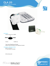
microphone
instrument
tape machine DAW
mixer
Basic Wiring Diagram

model
101
owner’s manual
page 8
specifications
GAIN RANGE (5dB steps)
Mic input 10-60dB
Hi-Z input -10-40dB
Mic input High gain version 20-70dB
Hi-Z input High gain version 0-50dB
Output trim attenuator 0 to -10dB
THD+N
@ 20dB Gain +20dBu out <0.00085%
@ 40dB Gain +20dBu out <0.0010%
@ 60dB Gain +20dBu out <0.0050%
INTERMODULATION DISTORTION
@ 40dB Gain +20dBu out
SMPTE/DIN 4:1 7kHz/50Hz <0.0020
NOISE - REFERRED TO INPUT
50Ω source <-130dB
150Ω source <-128dB
600Ω source <-124dB
CMRR
100Hz >68dB
1kHz >75dB
10kHz >65dB
PHASE DEVIATION (HPF off)
50Hz-25kHz <6°
FREQUENCY RESPONSE
Mic input @ 40dB Gain -3dB 4.5Hz-390kHz
Mic input @ 40dB Gain -0.5dB 10.5Hz-140kHz
Hi-Z input @ 20dB Gain -3dB 2.5Hz-195kHz
Hi-Z input @ 20dB Gain -0.5dB 6Hz-74kHz
IMPEDANCE
Mic input 3kΩ
Hi-Z input (unbalanced) 1MΩ
Hi-Z input (balanced) 2MΩ
Output 300Ω
PEAK LED METER
Green threshold -14dBu
Red threshold +16dBu
MAXIMUM OUTPUT LEVEL
100k Ohm load, 0.1% THD +25dBu
WEIGHT and DIMENSIONS
3.5lbs 1U rack mount x W8.5” x D6.75”
POWER CONSUMPTION
6VDC 800mA max

page 9
model
101
owner’s manual
WWW.GRACEDESIGN.COM
2434 30th street, boulder, CO 80301 USA
tel 303.443.7454 fax 303.444.4634
war ranty information
Grace Design warrants all of our products to be free of defective parts and workmanship for a
period of five years. This warranty period begins at the original date of purchase and is trans-
ferable to any person who may subsequently purchase the product during this time.
This warranty excludes the following conditions: normal wear and tear, misuse, customer neg-
ligence, accidental damage, unauthorized repair or modification, cosmetic damage and dam-
age incurred during shipment.
During the time of this warranty, Grace Design will repair or replace, at its option, any defec-
tive parts or repair defective workmanship without charge, provided the customer has ap-
propriate proof of purchase and that the product has its original factory serial number.
In order for Grace Design to provide efficient and timely warranty service, it is important that
you mail the completed warranty registration card enclosed with all of our products within
10 days of the original date of purchase. You may also register your product directly with
Grace Design by telephone (303-443-7454 Monday-Friday 9:00am to 5:00pm MST), or you
can register your product online at www.gracedesign.com.
This warranty is in lieu of all other warranties whether written, expressed, or implied, INCLUD-
ING ANY WARRANTIES OF MERCHANTABILITY OR FITNESS FOR A PARTICULAR PURPOSE.
In no event will Grace Design be liable for lost profits or any other incidental, consequential or
Exemplary damages, even if Grace Design is aware of the possibility of such damages. In no
event will Grace Design’s liability exceed the purchase price of the product
This warranty gives the customer specific legal rights. The customer may also have other
rights, which vary from state to state. Some states do not allow limitations on implied war-
ranties or consequential damages, so some of the limitations of the above may not apply to
a particular customer.

model
101
owner’s manual
page 10
Revision Page Change Date Initials
A-B Initial release
C all Revised layout 8/14/07 edg
Manual Revisions

page 11
model
101
owner’s manual

WWW.GRACEDESIGN.COM
2434 30th street, boulder, CO 80306-0204 USA
tel 303.443.7454 fax 303.444.4634
/