Omega OS550-BB Series User manual
- Category
- Environment thermometers
- Type
- User manual
This manual is also suitable for

OS550/OS550-BB Series
Industrial Infrared
Thermometer/Transmitter
MADE IN
omega.com
e-mail: [email protected]
For latest product manuals:
omegamanual.info
User’s Guide
Shop online at

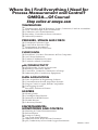
Servicing North America:
U.S.A.: One Omega Drive, Box 4047
ISO 9001 Certified Stamford, CT 06907-0047
Tel: (203) 359-1660
FAX: (203) 359-7700
e-mail: [email protected]
Canada: 976 Bergar
Laval (Quebec) H7L 5A1, Canada
Tel: (514) 856-6928
FAX: (514) 856-6886
e-mail: [email protected]
For immediate technical or application assistance:
U.S.A. and Canada: Sales Service: 1-800-826-6342/1-800-TC-OMEGA
®
Customer Service: 1-800-622-2378/1-800-622-BEST
®
Engineering Service: 1-800-872-9436/1-800-USA-WHEN
®
Mexico: En Espan˜ol: (001) 203-359-7803
e-mail: [email protected]
FAX: (001) 203-359-7807
Servicing Europe:
Czech Republic: Frystatska 184, 733 01 Karvina´, Czech Republic
Tel: +420 (0)59 6311899
FAX: +420 (0)59 6311114
Toll Free: 0800-1-66342
e-mail: [email protected]
Germany/Austria: Daimlerstrasse 26, D-75392 Deckenpfronn, Germany
Tel: +49 (0)7056 9398-0
FAX: +49 (0)7056 9398-29
Toll Free in Germany: 0800 639 7678
e-mail: [email protected]
United Kingdom: One Omega Drive, River Bend Technology Centre
ISO 9002 Certified Northbank, Irlam, Manchester
M44 5BD United Kingdom
Tel: +44 (0)161 777 6611
FAX: +44 (0)161 777 6622
Toll Free in United Kingdom: 0800-488-488
e-mail: [email protected]
OMEGAnet
®
Online Service Internet e-mail
omega.com [email protected]
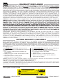
It is the policy of OMEGA Engineering, Inc. to comply with all worldwide safety and EMC/EMI
regulations that apply. OMEGA is constantly pursuing certification of its products to the European New
Approach Directives. OMEGA will add the CE mark to every appropriate device upon certification.
The information contained in this document is believed to be correct, but OMEGA accepts no liability for any
errors it contains, and reserves the right to alter specifications without notice.
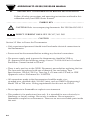
WARNING: These products are not designed for use in, and should not be used for, human applications.

NOTE
i
Unpacking Instructions
Remove the Packing List and verify that you have received all equipment, including
the following (quantities in parentheses):
OS550 or OS550-BB Series Infrared Thermometer with Sensor Head (1)
RS-232 Cable with connector/adapter (OS552, OS553, OS554) only (1)
CD Software ( OS552, OS553, OS554) only (1)
User’s Guide (1)
Optional Accessories:
From the Technical Library of ____________________________________
Model No. Description
OS550-MN Mounting Nut
OS550-MB Mounting Bracket
OS550-AP Air Purge Collar
OS550-MF Mounting Flange
OS550-WC Water Cool Jacket
OS550-LS Laser Sight
PSS-12 Power Supply, 12V regulated
PSU93 24V Power Supply, unregulated
If you have any questions about the shipment, please call the Customer Service
Department at
1-800-622-2378 or 203-359-1660. We can also be reached on the Internet at
omega.com
e-mail: [email protected]
When you receive the shipment, inspect the container and equipment for signs of
damage. Note any evidence of rough handling in transit. Immediately report any
damage to the shipping agent.
The carrier will not honor damage claims unless all shipping material
is saved for inspection. After examining and removing contents, save
packing material and carton in the event reshipment is necessary.

ii
OS550 Series
Industrial Infrared Thermometer
This page is intentionally blank

TABLE OF
CONTENTS
OS550/OS550-BB Series
Industrial Infrared Thermometer
iii
Page
Unpacking Instructions ...................................................................... i
Chapter 1 General Description .................................................... 1-1
1.1 Introduction ......................................................................................... 1-1
1.2 Thermometer Features ....................................................................... 1-2
1.2.1 Display Details...................................................................................... 1-3
1.2.2 Parts of the Thermometer .................................................................. 1-4
Chapter 2 Installing the Handheld Infrared Thermometer ............. 2-1
2.1 Installation ............................................................................................ 2-1
2.1.1 Sensor Head Installation ..................................................................... 2-1
2.1.2 Display Electronics Installation ......................................................... 2-1
2.1.3 OS550-BB Installation .......................................................................... 2-1
2.2 Sensor Head Dimensions ................................................................... 2-2
2.3 Display Electronics Dimensions ........................................................ 2-3
2.4 Display Mounting Dimensions ......................................................... 2-4
2.5 Mounting Bracket Dimensions .......................................................... 2-5
2.6 Mounting Nut Dimensions ................................................................ 2-5
2.7 Mounting Flange Dimensions ........................................................... 2-6
2.8 Air Purge Collar Dimensions ............................................................ 2-6
Chapter 3 Using the Infrared Thermometer .................................. 3-1
3.1 Using the Infrared Thermometer ...................................................... 3-1
3.1.1 Water Cool Jacket Accessory ............................................................. 3-1
3.2 How To Power the Thermometer...................................................... 3-2
3.2.1 Cable Connection ................................................................................. 3-2
3.2.2 Terminal Block Wire Connections .................................................... 3-2
3.3 Operating the Thermometer............................................................... 3-3
3.3.1 Field of View Charts ............................................................ 3-4, 3-5, 3-6
3.4 Measurement Techniques ................................................................... 3-7
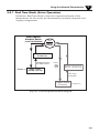
3.4.1 Real Time Mode (Active Operation) ................................................. 3-9
3.5.1 Adjusting Emissivity ......................................................................... 3-12
3.5.2 Calculating Temperature Values ......................................................3-13
3.5.3 Changing the Temperature for °F to °C.......................................... 3-13
3.5.4 Turning the Display Backlighting ON/OFF ...................................3-13
3.5.5 Using the Alarm Functions............................................................... 3-14
3.5.6 Using Ambient Target Temperature Compensation .....................3-16
3.5.7 Sending Temperature Data to a Serial Printer ................................3-17
3.5.8 Sending Temperature Data to a Personal Computer.....................3-19
3.5.9 Storing the Temperature Data on Command .................................3-22
3.5.10 Erasing the Temperature from Memory..........................................3-23
3.6 Recall Mode (Passive Operation)......................................................3-24
3.6.1 Reviewing the Last Parameters.........................................................3-26
3.6.2 Downloading Previously Stored Temperature Data .....................3-26
3.6.3 Reviewing Previously Stored Temperature Data...........................3-28

iv
TABLE OF
CONTENTS
OS550/OS550-BB Series
Industrial Infrared Thermometer
Page
Chapter 4 Laser Sight Accessory ................................................... 4-1
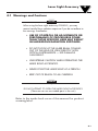
4.1 Warnings and Cautions ...................................................................... 4-1
4.2 Description ........................................................................................... 4-2
4.3 Operating the Laser ............................................................................. 4-3
4.3.1 Installing the Laser Sight onto the Thermometer............................ 4-3
4.3.2 Powering the Laser Sight Accessory ................................................. 4-3
Chapter 5 Maintenance ............................................................... 5-1
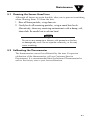
5.1 Cleaning the Lens ................................................................................ 5-1
5.2 Calibrating the Thermometer ............................................................ 5-1
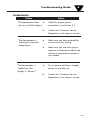
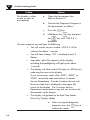
Chapter 6 Troubleshooting Guide ................................................ 6-1
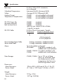
Chapter 7 Specifications .............................................................. 7-1
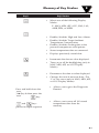
Chapter 8 Glossary of Key Strokes ............................................. 8-1
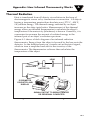
Appendix A How Infrared Thermometry Works .......................... A-1
Appendix B Emissivity Values ..................................................... B-1
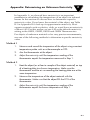
Appendix C Determining an Unknown Emissivity ........................ C-1
Addendum Rev.2/1999 .............................................................. D-1
Index ............................................................................................. I-1

1-1
General Description
1
1.1 Introduction
The OS550 Series Industrial Infrared (IR) Thermometers provide
non-contact temperature measurement up to 2500°F (1371°C). They
offer effective solutions for many non-contact temperature
applications, including the following:
• Predictive Maintenance: Tracking temperature shifts
which indicate pending failure in solenoid valves.
• Energy Auditing: Locating wall insulation voids to reduce
building heating costs.
• Food Processing: Taking accurate temperature readings
without direct contact with the food or packaging material.
The IR thermometer provides a custom backlit dual digital LCD
that displays both current and minimum, maximum, average or
differential temperatures. This versatile instrument provides:
• Measurable target distances from 5" to
approximately 200'
• Emissivity adjustable from 0.1 to 1.00 in 0.01 steps provides
ease of use when measuring a variety of surfaces.
• Continuous temperature measurement up to 4 times per
second.
• Audible and visual alarms. The high and low alarm points
are set via the keypad.
• Analog output, 1 mV/degree,4-20mA or 0-5VDC
which allows interfacing with data acquisition equipment
(including chart recorders, dataloggers and computers)
• RS232 serial communication to a PC or printer. This allows
downloading data for further analysis (OS552, OS553 and
OS554 only).
• Ambient target temperature compensation. This provides
more accuracy for measuring low emissivity targets.
• Record up to 100 temperature data points. Review the
recorded data on the thermometer LCD, as well as
downloading the data to a PC (OS553 and OS554 only).
• Last temperature recall.
• Backlit display useful in low ambient light conditions
• Laser Sighting is optional.

General Description
1
1-2
1.2 Thermometer Features
The thermometer is easy to use:
• Temperature readings are switchable from °F to °C via the
keypad.
• Parameters, such as target material emissivity and alarm
setpoints, can be set and remain in memory until reset.
This instrument has a rugged and functional design, including:
• Sealed keypad display.
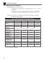
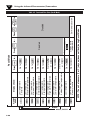
Table 1-1. OS550 Series Industrial Infrared Thermometer Features
*or 3°F whichever is greater
Features
OS551 OS552 OS553 OS554
Accuracy* ±1% rdg ±1% rdg ±1% rdg ±1% rdg
Range 0 to 750°F 0 to 1000°F 0 to 1600°F 0 to 2500°F
(-18 to 400°C) (-18 to 538°C) (-18 to 870°C) (-18 to 1371°C)
Emissivity adjustable adjustable adjustable adjustable
Backlit Dual
standard standard standard standard
Display
Distance to
Spot Ratio
Differential
standard standard standard standard
Temperature
Min/Max
standard standard standard standard
Temperature
Average
standard standard standard standard
Temperature
High Alarm standard standard standard standard
Low Alarm – standard standard standard
Ambient Target
Temperature – standard standard standard
Compensation
RS-232 Output – standard standard standard
Data Storage – – standard standard
Last Temperature
standard standard standard standard
Recall
See Field of View Charts, pages 3-4, 3-5, 3-6

1-3
General Description
1
1.2.1 Display Details
Figure 1-1. Display and Keypad View
Table 1-2. Display Details
Key Description
➀
Display Mode displays one of the following:
E (Emissivity) HAL (High Alarm Setpoint)
MAX (Maximum Temperature) LAL (Low Alarm Setpoint - only on OS552/OS553/OS554)
MIN (Minimum Temperature) AMB (Ambient Target Temp - only on
OS552/OS553/OS554)
dIF (Differential Temperature) PRN (Print Data - OS552, OS553 and OS554 only)
AVG (Average Temperature) MEM (Store Temperature Data - only on OS553/OS554)
➁
Data associated with one of the Display Modes
➂
Backlighting Icon - allows the display to be viewed under low ambient light
➃
Displays the units of measure in either °F or °C
➄
Main display - displays the current temperature
➅
Power On Lock / Enables or Disables alarms
➆
▲ for incrementing data; is for turning on/off the backlighting
➇
▼ for decrementing data; is for changing the units of measure from
°F to °C or vice versa
➈
Function key for scrolling through the display modes
➉
Display Icons
Ambient Target Temperature Low Alarm
High Alarm Print Data
MAX658
750
AT C
HAL
LAL
PRN
F C
LOCK
FUNC
F-C
▼
▼
-
2
1
10
9
8
3
4
5
6
7

1-4
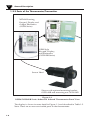
1.2.2 Parts of the Thermometer/Transmitter
Figure 1-2.
OS550/OS550-BB Series Industrial Infrared Thermometer Front View
The display is shown in more detail in Figure 1-1 and described in Table 1-2.
Note: There are no user-serviceable parts in the thermometer.
Shown with optional mounting bracket,
OS550-MB and mounting nut OS550-MN
Sensor Head
General Description
1
NEMA Housing,
Keypad, Display and
Output Electronics
(OS550 Series)
OEM Style
Keypad, Display,
and Electronics
(OS550-BB Series)

2-1
2
2.1 Installation
2.1.1 Sensor Head Installation
The OS550’s sensor head is made of black anodized aluminum. Both ends
of the sensor head come with a 1
1
⁄2 - 20 standard threaded mounting
connection. The sensor head is connected to the main display electronics via
a 15' shielded cable and environmentally sealed twist lock connector.
Mounting accessories are available. See pages 2-4, 2-5 for model numbers
and dimensions. Also see page 2-2 for sensor head dimensions.
If the sensor head is used in an environment where the
ambient temperature is above 122°F (50°C), the water
cool jacket accessory (OS550-WC) must be used to
maintain accuracy and prevent damage to the sensor
head. See Chapter 3.1.
2.1.2 OS550 Series Display NEMA Housing Installation
The OS550 Series’ main display and electronic’s housing is environmentally
sealed and weather tight. Mounting ears are provided making mounting
easy. Mount the main electronics assembly in a location that you can easily
access to view the LCD and make program changes to the unit. See case and
mounting plate dimensions on page 2-3.
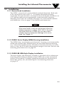
2.1.3 OS550-BB OEM Style Display Installation
The main display and electronics assembly is provided with an aluminum
mounting plate making installation of this OEM style system economical
and easy to customize. Assembly should be mounted in a location that is
free of dirt, grease, oils, and other liquids. See mounting dimension
on page 2-4.
Installing the Infrared Thermometer
NOTE

Installing the Infrared Thermometer
2
2-2
2.2 Sensor Head Dimensions
Fig. 2-1. Sensor Head Dimensions
29.2
(1.15)
29.2
(1.15)
41.1
(1.62) DIA.
38.1
(1.50) DIA.
109.2
(4.30)
160.3
(6.31)
1
1
⁄
2
x 20 THREAD
1
1
⁄
2
x 20 THREAD

2-3
2.3 OS550 Display Electronics Dimensions
Fig. 2-2. Main Display NEMA Housing with
Mounting Brackets Dimensions
Installing the Infrared Thermometer
2
131.3
(5.17) TYP.
Ø 4.37 (0.172) MOUNTING HOLE
(4 PLACES)
50.0
(1.97) TYP.

2-4
Installing the Infrared Thermometer
2
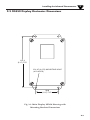
2.4 OS550-BB Series Display Mounting Dimensions
Fig. 2-3. OEM Style Main Display with Mounting Plate
26.4
(1.04)
31.0
(1.22)
57.4
(2.26)
Ø 5.16 (0.203) THRU TYP. (4 PLACES)
WILL FIT UP TO A
#10 SCREW OR BOLT
118.4
(4.66)
26.4
(1.04)
57.4
(2.26)
5.1
(.20) TYP.
91.4
(3.60)

2-5
Installing the Infrared Thermometer
2
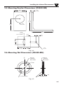
2.5 Mounting Bracket Dimensions (OS550-MB)
2.6 Mounting Nut Dimensions (OS550-MN)
50.8
(2.00)
57.2
(2.25)
38.61
Ø (1.520)
88.9
(3.50)
6.4
(.25) REF
88.9
(3.50)
12.7
(.50)
25.4
(1.00)
28.58
(1.125)
22.23
(.875)
25.4
(1.00)
3.18
R (.125)
3.18
R (.125)
TYP. 2 PLACES
.020 x 45
CHAMFER
BOTH SIDES
.020 x 45
CHAMFER
BOTH SIDES
1 1/2-20-2B THRU MED. DIAMOND NURL
.250
C
L
o
2.00
Fig. 2-4
Fig. 2-5

Installing the Infrared Thermometer
2
2-6
2.7 Mounting Flange Dimensions (OS550-MF)
2.8 Air Purge Collar Dimensions (OS550-AP)
6.35
(.250)
38 (1.5) - 20 THREAD
6.35 (.250)
THRU TYP. (3 PLACES)
3 HOLES ON Ø 71.1 (2.80)
BOLT CIRCLE
TYP. 3 PLACES
120
Ø 89 (3.5)
21.59
(.850)
1/8 N.P.T. TAP THRU
51 (2.0) DIA.
38 (1.5) – 20 THREAD
Fig. 2-6
Fig. 2-7

3-1
Using the Infrared Thermometer
3
3.1 Using the Infrared Thermometer
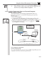
3.1.1 Water Cool Jacket Accessory
When using the OS550 sensor head in an ambient temperature environment
above 50°C (122°F), the OS550-WC Water Cooling Jacket option must be
used to maintain the accuracy and response time of the unit. Two
1
⁄
8
" N.P.T.
compression fittings are provided for connection to copper water lines. A
constant flow of approx. 0.5 GPM of clean, room temperature water is
sufficient to protect the instrument and maintain accuracy up to 85°C
(185°F). This option can be installed in the field.
Fig 3-1. Water Cool Jacket Dimensions
OS550-WC
Ø 70.4 (2.77)
63.5 (2.50)

Using the Infrared Thermometer/Transmitter
3
3-2
3.2 How To Power the Thermometer
3.2.1 OS550 Series Cable Connection
The OS550 Series thermometer comes with a built-in 4.5 m (15')
power/output cable. Power and output connections are made to the
cable via stripped wire ends located at one end of the cable. The
power/output cable can be shortened or extended in the field if needed.
See table 3-1 below for wire Connection.
Power Cable Connections – Table 3-1
Output Cable Connections
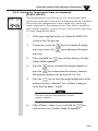
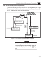
3.2.2 OS550-BB Series Terminal Block Wire Connections
Figure 3-1
Model -MV -MA -V1
Analog
1mV/°C or °F 4 to 20 mA 0-5 VDC
Output
Connection (+) White Wire (-) Green Wire
Power Connection: 7-24 VDC@80Ma
(+) Red Wire (-) Black Wire Earth Ground-Barewire
5
4
3
2
1
6
7
8
9
10
11
12
SENSOR HEAD RED WIRE
SENSOR HEAD BLACK WIRE
SENSOR HEAD GREEN WIRE
SENSOR HEAD WHITE WIRE
SENSOR HEAD BARE WIRE - SHIELD
DC POWER SUPPLY (EARTH GROUND)
- ANALOG OUTPUT
+ ANALOG OUTPUT
- DC POWER SUPPLY
+ DC POWER SUPPLY (7-24 Vdc)
RS-232 (TRANSMIT)
RS-232 (RECEIVE)
RS-232 (GROUND)

3-3
Using the Infrared Thermometer/Transmitter
3
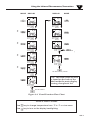
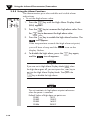
3.3 Operating The Thermometer
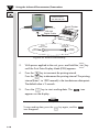
1. After installing the thermometer (see section 2.1) and connecting
power (see section 3.2), your unit will be ready for use.
Your unit has been shipped to you with the SLEEP/ON switch in the
“SLEEP” position. Place the switch in the “ON” position to turn your
unit on and begin to make measurements.
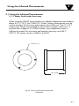
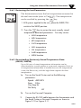
2. The optical field of view of the thermometers sensor head should fall
within the area of the target being measured.
See Figure 3-2. Figures 3-3 through 3-8 show the fields of view vs.
distance for the various thermometers.
Figure 3-2. Field of View Positions
3. The target temperature and emissivity are displayed on the LCD.
Determine the emissivity of the target (refer to Appendix B).
Press the key to increment the target emissivity.
Press the key to decrement the target emissivity.
Field of View
Target
(ACCEPTABLE)
(UNACCEPTABLE)
OS550 SERIES KEYPAD PARTIAL VIEW
Display
Mode
Display
Icons
Scrolls
Through
Display
Modes
ON
SLEEP
FUNC
SLEEP/ON SWITCH

Using the Infrared Thermometer/Transmitter
3
3-4
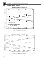
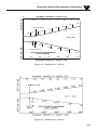
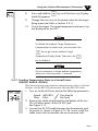
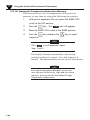
Figure 3-3. OS550 Series (-1 FOV)
Figure 3-4. OS550 Series (-2 FOV)
7.0
.35" @ 24"
1.6
9mm @ 610 mm
.8
21
42
181
.9
22
4.0
101
0
3
16102 5
SPOT DIA.* (MM)
*SPOT DIAMETER MEASURED
AT 90% ENERGY
5.0
0
.61
1.5
1.0
3.0
SPOT DIA.* (IN)
DISTANCE: SENSOR TO OBJECT (FT)
DISTANCE: SENSOR TO OBJECT (M)
D:S = 68:1
3.3.1 Field of View Charts
Page is loading ...
Page is loading ...
Page is loading ...
Page is loading ...
Page is loading ...
Page is loading ...
Page is loading ...
Page is loading ...
Page is loading ...
Page is loading ...
Page is loading ...
Page is loading ...
Page is loading ...
Page is loading ...
Page is loading ...
Page is loading ...
Page is loading ...
Page is loading ...
Page is loading ...
Page is loading ...
Page is loading ...
Page is loading ...
Page is loading ...
Page is loading ...
Page is loading ...
Page is loading ...
Page is loading ...
Page is loading ...
Page is loading ...
Page is loading ...
Page is loading ...
Page is loading ...
Page is loading ...
Page is loading ...
Page is loading ...
Page is loading ...
Page is loading ...
Page is loading ...
Page is loading ...
Page is loading ...
Page is loading ...
Page is loading ...
Page is loading ...
Page is loading ...
Page is loading ...
Page is loading ...
Page is loading ...
Page is loading ...
Page is loading ...
Page is loading ...
Page is loading ...
Page is loading ...
Page is loading ...
Page is loading ...
Page is loading ...
Page is loading ...
Page is loading ...
-
 1
1
-
 2
2
-
 3
3
-
 4
4
-
 5
5
-
 6
6
-
 7
7
-
 8
8
-
 9
9
-
 10
10
-
 11
11
-
 12
12
-
 13
13
-
 14
14
-
 15
15
-
 16
16
-
 17
17
-
 18
18
-
 19
19
-
 20
20
-
 21
21
-
 22
22
-
 23
23
-
 24
24
-
 25
25
-
 26
26
-
 27
27
-
 28
28
-
 29
29
-
 30
30
-
 31
31
-
 32
32
-
 33
33
-
 34
34
-
 35
35
-
 36
36
-
 37
37
-
 38
38
-
 39
39
-
 40
40
-
 41
41
-
 42
42
-
 43
43
-
 44
44
-
 45
45
-
 46
46
-
 47
47
-
 48
48
-
 49
49
-
 50
50
-
 51
51
-
 52
52
-
 53
53
-
 54
54
-
 55
55
-
 56
56
-
 57
57
-
 58
58
-
 59
59
-
 60
60
-
 61
61
-
 62
62
-
 63
63
-
 64
64
-
 65
65
-
 66
66
-
 67
67
-
 68
68
-
 69
69
-
 70
70
-
 71
71
-
 72
72
-
 73
73
-
 74
74
-
 75
75
-
 76
76
-
 77
77


Omega OS550-BB Series User manual
- Category
- Environment thermometers
- Type
- User manual
- This manual is also suitable for
Ask a question and I''ll find the answer in the document
Finding information in a document is now easier with AI
Related papers
-
Omega OS550A/OS550A-BB Series Owner's manual
-
-
Omega Engineering OSXL650 and OSXL653 User manual
-
-
-
-
-
Omega SP-001, SP-002 Owner's manual
-
-
Other documents
-
Dwyer Model WT-10 User manual
-
Renkforce E0001TA Owner's manual
-
Broan PPH3RF Installation guide
-
 LIFX L3BEAMKITUS Installation guide
-
Aktakom ATE-2509 User manual
-
 Ironton Infrared 8:1 Thermometer Owner's manual
-
 WINTACT WT320 User manual
-
 Lutron Electronics TM-958 User manual
-
-


