Page is loading ...

WARNING:
IF THE INFORMATION IN THESE INSTRUC-
TIONS ARE NOT FOLLOWED EXACTLY, A FIRE
OR EXPLOSION MAY RESULT CAUSING PROP-
ERTY DAMAGE, PERSONAL INJURY OR LOSS
OF LIFE.
FOR YOUR SAFETY:
DO NOT STORE OR USE GASOLINE OR OTHER
FLAMMABLE VAPORS AND LIQUIDS IN THE
VICINITY OF THIS OR ANY OTHER APPLIANCE.
INSTALLATION:
INSTALLATION AND SERVICE MUST BE PER-
FORMED BY A QUALIFIED INSTALLER, SER-
VICE AGENCY OR LICENSED GAS SUPPLIER.
WHAT TO DO IF YOU SMELL GAS:
• DO NOT TRY TO LIGHT ANY APPLIANCE.
• DO NOT TOUCH ANY ELECTRICAL
SWITCHES.
• DO NOT USE THE PHONE IN YOUR
BUILDING. IMMEDIATELY CALL YOUR GAS
SUPPLIER FROM A NEIGHBOR’S PHONE.
• FOLLOW YOUR GAS SUPPLIER’S
INSTRUCTIONS.
• IF YOU CANNOT REACH YOUR GAS
SUPPLIER, CALL THE FIRE DEPARTMENT.
AVERTISSEMENT:
ASSUREZ-VOUS DE BIEN SUIVRE LES IN-
STRUCTIONS DANS CETTE NOTICE POUR
REDUIRE AU MINIMUM LE RISQUE D’INCENDIE
OU POUR EVITER TOUT DOMMAGE MATERIEL,
TOUTE BLESSURE OU MORTALIT’E.
NE PAS ENTREPOSER NI UTILISER D’ESSENCE
NI OU LIQUIDES INFLAMMABLES DANS LE
VOISINAGE DE CET APPAREIL OU DE TOUT
AUTRE APPAREIL.
L’INSTALLATION LE SERVICE DOIVENT
ETRE EXECUTES PAR UN INSTALLATEUR
QUALIFIE, AGENCE DE SERVICE OU LE
FOURNISSEUR DE GAZ.
QUE FAIRE SI VOUS SENTEZ UNE ODEUR DE
GAZ.
• NE PAS TENTER D’ALLUMER L’APPAREIL
• NE TOUCHEZ A AUCUN INTERRUPTEUR.
• NE PAS VOUS SERVIR DES TELEPHONES
SE TROUVANT DANS LE BATIMENT OU VOUS
VOUS TROUVEZ.
• APPELEZ IMMEDIATEMENT VOTRE
FOURNISSEUR DE GAZ CHEZ UN VOISIN.
SUIVEZ LES INSTRUCTIONS DU FOURNISSEUR.
• SI VOUS NE POUVEZ REJOINDRE LE
FOURNISSEUR DE GAZ, APPELEZ LE SER-
VICE DES INCENDIES.
US
Warnock Hersey
C
GF 200 DV
Lillehammer
Gas Heater
Installation
and
Operation
Instructions

2
Welcome to Jøtul...
Congratulations on the purchase of your new
Jøtul GF 200 DV Lillehammer - a direct vented gas
heater especially designed and approved for
installation into a variety of configurations where
close clearance to combustibles is required.
We at Jøtul are glad you’ve made the decision to
warm your hearth with a Jøtul product. Your new
Lillehammer benefits from our experience as the
world’s largest manufacturer of solid fuel burning
appliances for over 140 years. We’ve been making
fine quality cast iron wood and coal stoves and
fireplaces continuously since 1853.
In the Lillehammer, we’ve combined advanced gas
technology with the warm, traditional elements of
cast iron. With proper care and use, your Jøtul stove
will provide you with many years of safe, dependable
and satisfying service.
Please take a few minutes to familiarize yourself
with this manual and the features of your
Lillehammer gas stove. Locate the serial number
stamped onto the Rating Plate which is attached to
the bottom of the stove. Record this number in the
Maintenance Record section of this manual for
future reference.

3
Table of Contents
Specifications .................................................. 3
General Information ...................................... 5
Safety Information .........................................6
Hearth Protection Requirements ................6
Clearance Requirements ............................... 7
Mantel and Trim Clearances ...................7
Venting Requirements ...................................8
Draft Restrictors ........................................8
Vertical Vent Systems ............................... 9
Co-linear Hearthmount Systems ........ 10
Vent Height Requirements................... 11
Horizontal Vent Options ....................... 12
Wall Shield Installation ......................... 13
Vent Termination Clearances............... 14
Mobile Home Installation .......................... 15
Fuel Conversion ............................................ 16
Gas Connection ............................................ 17
Gas Pressure ................................................. 18
High Altitude Adjustment ......................... 19
Air Shutter Adjustment .............................. 20
Log Set Installation ...................................... 20
Thermostat / Remote Control ................... 21
Checking the System .................................. 21
Operation ...................................................... 22
Maintenance ................................................ 23
Maintenance Record ................................... 24
Parts Illustration........................................... 25
Replacement Parts List ............................... 26
Lighting Instructions .................... Back Cover
Jøtul GF 200 Lillehammer
Direct Vent Gas Heater
Manufactured and Distributed by:
Jøtul A.S.A.
Fredrikstad, Norway
Jøtul North America
Portland, Maine
Test Standards
This appliance complies
with National Safety
standards and is tested
and listed by Intertek
Testing Services of
Middleton, Wisconsin to ANSI Z21.88-1998
(NFPA 54) and CSA 2.33-M98 for Canada.
DO NOT ATTEMPT TO ALTER OR MODIFY THE
CONSTRUCTION OF THE APPLIANCE OR ITS
COMPONENTS. ANY MODIFICATION OR ALTER-
ATION WILL VOID THE WARRANTY, CERTIFICA-
TION AND LISTING OF THIS APPLIANCE.
US
Warnock Hersey
C
Suggested Tools for
Installation and Service
• External regulator (for Propane only)
• Piping which complies with local code
• Manual shutoff valve - T-Handle in MA
• Sediment trap - if required by code
• Tee joint
• Pipe wrench
• Pipe sealant
• 10mm open end wrench
• 1/2”, 7/16” open end wrench
• Phillips head screwdriver
• Flat head screwdriver
• 1/4” nut driver
• Gloves
• Safety glasses
• Torx T20 screwdriver
• Leak test solution
• Reciprocating Saw
• Power Drill
THIS PRODUCT MUST BE INSTALLED BY
A LICENSED MASTER PLUMBER OR GAS-
FITTER WHEN INSTALLED IN THE COM-
MONWEALTH OF MASSACHUSETTS.

4
Jøtul GF 200 DV Lillehammer
Specifications
Figure 1. Dimensional Views - GF 200 DV
Lillehammer
GF 200 DV Lillehammer Options
• Fuel Conversion Kit - NG.............................. 155349
• Fuel Conversion Kit - LP ............................... 155350
• High Altitude Conversion Kit - NG ........... 154371
• High Altitude Conversion Kit - LP ............. 154373
• Wall Thermostat ............................................ 750003
• Remote Control .............................................. 129706
• Mobile Home Floor Bracket Kit ................. 154342
Rear Exit
Centerline
18”
460 mm
13”
330 mm
18 1/2”
470 mm
16 1/2”
420
mm
24”
610 mm
22 3/4”
560
mm
Input Rates
Natural Gas
18,000 BTU/hr. maximum input
13,500 BTU/hr. minimum input
Propane
18,000 BTU/hr. maximum input
13,500 BTU/hr. minimum input
Inlet Pressure: MIN MAX
Natural Gas: 5.0 WC (1.24 kPa) 7.0 WC (1.74 kPa)
Propane: 11.0 WC (2.73 kPa) 13.5 WC (3.36 kPa)
Manifold Pressure: MIN MAX
Natural Gas: 2.2 WC (.54 kPa) 3.5 WC (.87 kPa)
Propane: 6.5 WC (1.61 kPa) 10.0 WC (2.49 kPa)
Efficiency: 82%
Steady State (A.F.U.E.): 73%
Piezo Ignitor / Standing Pilot
The Jøtul GF 200 DV Lillihammer is a Direct Vent
wall furnace designed as a sealed combustion, air
circulating gas appliance for residential applications.
This appliance is approved for installation using 6 5/
8" X 4" vent pipe from the following manufacturers:
Simpson Dura-Vent GS
Security Vent, Ltd.
Amerivent Inc.
The Jøtul Lillehammer gas stove is designed to
burn NATURAL GAS or PROPANE only. It is shipped
from the factory equipped to burn Natural Gas. If use
with Propane is desired, the stove must first be
converted for use with that gas. Use the LP Fuel
Conversion Kit included with this stove See page 15.

5
DO NOT OPERATE THE LILLEHAMMER
GAS STOVE WITH THE GLASS FRONT
REMOVED, CRACKED OR BROKEN.
REPLACEMENT OF THE GLASS SHOULD
BE DONE BY A LICENSED OR QUALIFIED
SERVICE PERSON. ONLY REMOVE
GLASS FOR ROUTINE SERVICE.
ALWAYS HANDLE GLASS CAREFULLY.
SEE THE MAINTENANCE CHAPTER FOR
INSTRUCTIONS ON REPLACING THE
GLASS PANEL.
General Information
n THIS HEATER MUST BE INSTALLED AND MAIN-
TAINED BY A QUALIFIED SERVICE AGENCY.
n THIS APPLIANCE MUST NOT BE CONNECTED TO A
CHIMNEY OR FLUE SERVING ANY OTHER APPLI-
ANCE.
n The installation and repair of this appliance must
be done by a qualified service person. Failure to
properly install and maintain this heater could
result in an unsafe or hazardous installation,
which may result in a fire, explosion, property
damage, personal injury or loss of life.
n This appliance should be inspected before use and
at least annually. More frequent cleaning may be
required due to excessive lint from carpeting,
bedding material, etc. It is imperative that control
compartments, burners, and circulating air
passageways of the appliance be kept clean.
n The installation must conform to local codes. Your
local Jøtul dealer can assist you in determining
what is required in your area for a safe and legal
installation. Some areas require a permit to install
a gas burning appliance. Always consult your
local building inspector, or authority having
jurisdiction, to determine what regulations apply
in your area.
n REMEMBER: Your local officials have final author-
ity in determining if a proposed installation is
acceptable. Any requirement that is requested by
the local authority having jurisdiction, that is not
specifically addressed in THIS manual, defaults to
local code. In the absence of local codes, the
installation requirements must comply with the
current National codes. In the U.S., these require-
ments are established in the National Fuel Code,
ANSI Z223.1.(NFPA 54). In Canada, the codes have
been established in CAN/CGA B149 Fuel Installa-
tion Code.
n Installer l’appareil selon les codes ou reglements
locaux, ou, en l’absence de tels reglements, selon
les Codes d’installation CAN/CGA-B149.
n DO NOT OPERATE THIS STOVE IF ANY PART HAS
BEEN UNDER WATER. Call a qualified service
technician to inspect the heater and to replace
any part of the control system and any gas control
which may have been under water.
n Ne pas se servir de cet appareil s’il a ete’ plonge
dans l’eau, completement ou en partie. Appeler
un technicien qualifie pour inspecter l’appareil et
remplacer toute partie du syste’me de controle et
toute commande qui ont ete plonges dans l’eau.
Glass Panel

6
Locating the Stove
In selecting the location, the aesthetic and func-
tional use of the appliance are primary concerns.
However, proper venting systems and access to the
fuel supply are also important issues. Due to the
high surface temperatures of the Lillehammer, one
must also consider the proximity of traffic ways,
furniture, draperies, etc.
This appliance may be located on or near
conventional construction materials. HOWEVER,
always maintain the proper clearances to combus-
tibles, as this provides adequate ventilation air
around the appliance.
Hearth Requirements
The Jøtul GF 200 Lillehammer gas stove CANNOT be
installed directly on carpeting, vinyl flooring, Pergo®,
or linoleum. If it is desired to install this appliance on
any combustible material OTHER THAN WOOD, a floor
pad must be installed that is either metal, wood or a
listed hearth pad. This floor protection must extend
the full width and depth of the appliance. It is not
necessary to remove the carpeting, vinyl or linoleum
from underneath the floor protection.
Safety Information
The Jøtul GF 200 Lillehammer gas stove during
normal operation, will reach high surface tempera-
tures. Read and follow the safety guidelines below.
• Due to the high operating temperatures, this
appliance should be located out of traffic and
away from furniture and draperies.
• Children and adults should be alerted to the
hazards of high surface temperatures and should
stay away to avoid burns or clothing ignition.
• Young children should be supervised while they
are in the same room as the Lillehammer gas
stove.
• Clothing or other flammable materials should not
be placed ON or NEAR the Lillehammer gas stove.
Surveiller les enfants. Garder les vetements, les
meubles, l’essence ou autres liquides a vapeur
inflammables loin de l’appareil.
• NEVER store or use gasoline or any other flam-
mable vapors or liquids in the vicinity of the
Lillehammer gas stove.
• Never burn any other materials in your
Lillehammer gas stove, it is strictly designed for
use with natural gas or propane fuel ONLY.
• Any safety screen, glass or guard removed for
servicing the appliance must be replaced prior to
operating the appliance.
The following clearances and hearth require-
ments are the minimum requirements when install-
ing the Lillehammer gas stove near or on combustible
surfaces. Always provide adequate access around the
appliance for servicing and proper operation.
A combustible surface is anything that can burn
(i.e. sheet rock, wall paper, wood, fabrics etc.). These
surfaces are not limited to those that are visible and
also include materials that are behind non-combus-
tibles.
If you are not sure of the combustible nature of a
material, consult your local fire officials. Remember,
“Fire Resistant” materials are considered combustible:
they are difficult to ignite, but will burn. Also, “fire-
rated” sheet rock is considered combustible.
Figure 2. Lillehammer Hearth Protection
Minimum
Hearth
Protection
Min. Depth
16 1/2”
420 mm
Min.
Width
22 3/4”
580 mm

7
Clearance to Combustibles
Minimum Stove Clearance
Rear 0” (0mm)
Ceiling 17” (432mm)
Corner 2” (51mm)
Right Side 2” (51mm)
Left Side *10” (255mm)
* Necessary for complete access to pull out required Lighting
Instructions Plate.
Minimum Vent Pipe Clearance
Horizontal runs:
Off the top of the pipe - 2” (26mm)
Off the sides and bottom - 1” (26mm)
Vertical runs:
All sides - 1” (26mm)
See Figures 4 and 5.
Parallel Installation
Corner Installation
Mantel and Trim Clearances
Alcove Installation
Maximum Depth: 24” (610mm)
Minimum Width: 35” (890mm)
Minimum Ceiling Height: 42” (1067mm)
Figure 5. Clearance to rear corners.
Figure 3. Mantel / Trim Clearances
2”
51mm
2”
51mm
24”or greater depth
or ceiling
12” or less
6” or
less
1” deep
trim
must be
2” off
the top of
the
stove.
6”
153 mm
2”
51 mm
10”
255 mm
17”
432 mm
Figure 4. Clearances with stove parallel to the walls
* Allow 10” on left side of the appliance
for complete access to the lighting
instructions and control valve.
Rear Wall Clearance: 0” (ZERO mm)
Left Side*
10”
230 mm
Max.
Alcove
Depth
24”
610
mm
Right
Side
2”
25
mm

8
Install the Exhaust Restrictor Plate
1. Remove the Top Plate to access the Glass Panel.
2. Release the Glass Panel latches and lift the panel
straight up off of the firebox.
2. Carefully remove the Log Set pieces from the
firebox.
2. Use a 1/4” nut driver to remove the two lower
sheet metal screws located inside the firebox
below the exhaust outlet. Install the rectangular
restrictor plate over the lower half of the outlet
and secure it using the same screws.
Vent Restriction
The GF 200 DV Lillehammer includes two draft
restrictor plates found in the parts bag. These must
be installed togethe within the stove in the follow-
ing vent configurations:
1) ANY vertically vented installation
2) ANY horizontal vent utilizing a Snorkel
Termination.
Additional restriction may be necessary, depending
on the vent height.
The plates are used to compensate for draft
characteristics that would otherwise interfere with
proper burner performance such as low heat output,
weak flame picture, or inefficient combustion. Both
restrictors must be installed. See Figs. 6 and 7.
Exhaust
Outlet
Lower Exhaust Screws
Rectangular
Exhaust
Restrictor
Plate
Firebox
Exhaust
Baffle
Figure 6. Install the Exhaust Restrictor Plate.
SEALANT
Venting Requirements
There are three types of venting configurations
approved for use with the Lillehammer gas stove:
• Hearthmount Co-Linear (Vertical Termination)
• Vertical Venting (Vert ical Termination)
• Horizontal Termination (Horizontal Termination)
The Lillehammer is approved for use with the
vent systems listed below. Use parts of one manu-
facturer only - DO NOT MIX VENT COMPONENTS
FROM DIFFERENT MANUFACTURERS IN THE SAME
SYSTEM.
• Simpson Dura-Vent GS
• Amerivent Corporation
• Security Vent Ltd.
Installation of any components not manufac-
tured or approved by Jøtul or failure to meet all
clearance requirements will void all warranties and
could result in property damage, bodily injury, or
serious fire.
The approved vent configurations described in
this manual are derived from extensive testing
under controlled laboratory conditions. Gas appli-
ance performance can be negatively affected by
variables present in the installation environment, i.e:
atmospheric pressure, strong prevailing winds,
adjacent structures and trees, snow accumulation,
etc. These conditions should be taken into consider-
ation by the installer and stove owner when plan-
ning the vent system design.
IMPORTANT
• JOINT SEALING REQUIREMENT:
APPLY A 1/8” BEAD OF HIGH-
TEMPERATURE (750°F) SEAL-
ANT TO THE MALE SECTION OF
THE INNER VENT PIPE. SEE
FIG. 9. THE CEMENT
SHOULD FORM A SEAL
BETWEEN THE INNER
AND OUTER PIPES.
• NEVER MODIFY ANY
VENTING COMPONENT, OR USE
ANY DAMAGED VENTING PRODUCT.
• THE GAS APPLIANCE AND VENT SYSTEM MUST BE
VENTED DIRECTLY TO THE OUTSIDE OF THE
BUILDING AND NEVER ATTACHED TO A CHIMNEY
SERVING A SOLID FUEL OR GAS BURNING APPLI-
ANCE. EACH DIRECT VENT GAS APPLIANCE MUST
HAVE ITS OWN SEPARATE VENT SYSTEM. COM-
MON VENT SYSTEMS ARE PROHIBITED.
• IF VENTING SYSTEM IS DISASSEMBLED FOR ANY
REASON, REINSTALL PER THE INSTRUCTIONS
Install the Air Inlet Restrictor Plate
1. Using a 1/4” nut driver, remove the left hand
sheet metal screw holding the Air Deflector to
the rear wall of the firebox. See Fig. 7.
2. Slide the Air Inlet Restrictor down along the rear
wall of the firebox behind the Air Deflector, so
that the Restrictor plate completely covers the air
intake inlet.
3. Secure both the Restrictor plate and the Deflector
to the rear wall using the same screw.

9
35 Ft.
(10.67 m)
30 Ft.
(9.14 m)
25 Ft.
(7.62 m)
20 Ft.
(6.10 m)
15 Ft.
(4.57 m)
5 Ft.
(1.52 m)
1 Ft.
(.30 m)
10 Ft.
(3.05 m)
10 Ft.
(3.05 m)
5 Ft.
(1.52 m)
VERTICAL RUN
HORIZONTAL RUN
Figure 7. Install the Air Inlet Restrictor Plate.
Rear Wall
of Firebox
Air
Deflector
Remove
this
screw
only
Air Intake Restrictor Plate
Table 1. Vertical vent run Termination Window.
Vertical Venting Requirements
These requirements apply to any installation
that includes a verrtical vent run.
The GF 200 DV Lillehammer can be vertically vented
through a roof or ceiling following these guidelines:
n Steep roofs, nearby trees, and predominantly windy
conditions can contribute to poor draft or down-draft
occurances. Increasing the height of the vent may
alleviate these conditions.
n Use Simpson Dura-Vent Wall Straps (#988) to support
an offset pipe run at three feet intervals to avoid
excessive stress on the offsets.
n Whenever possible use 45° elbows instead of 90°
elbows as they are less restrictive to exhaust gas and
intake air flow.
n GAS VENT RULE: In no case shall any discharge
opening on the cap be less than 2' (610mm) horizon-
tally from the roof surface. See Figure 11.
n A firestop is required at every floor. The opening
should be framed to 10" X 10" inside dimension.
Simpson Dura-Vent Ceiling Firestop #943 is required.
n Any venting that is exposed above the first floor,
regardless of attic space or living space, must be
enclosed. Always maintain the required 1" clearance
from all sides of the vertical vent system.
n Install the Exhaust Gas Restrictor in all Vertically
Terminated vent systems. See the Adding Restriction
section on page 8.
n A vertical run in any horizontally-terminated system
must rise a minimum of 1 ft. See Fig. 12-5.
VERTICAL VENTING, OR ANY HORIZONTAL
VENTING WITH VERTICAL RISE, MUST
TERMINATE (END) WITHIN THE SHADED AREA.
• RESTRICTOR REQUIRED ON ALL VERTICAL
VENTING.
• ALWAYS MAINTAIN THE PROPER CLEAR-
ANCES TO COMBUSTIBLES.
Minimum
Vertical
Rise =1 ft
for a
Horizontal
Termination
.

10
Co-linear Hearthmount Installation
The Jøtul GF 200 DV Lillehammer may be vented
through a masonry fireplace using Simpson Dura-
Vent Chimney Liner Conversion Kit 923GK. When
installed in the manner described below, this system
can improve the performance of the appliance in
cold climate situations, as well as simplify the vent
installation.
These guidelines must be followed:
1. Prior to the installation, the chimney flue must be
thoroughly cleaned and inspected by a qualified
chimney service person.
2. In a masonry chimney, a fireclay liner or listed
steel liner, must be present the entire length of
the chimney.
3. No appliance can be installed into a chimney flue
serving any other appliance of any kind.
4. The minimum length of the AIR INTAKE FLEX is 6
feet- measured off of the back of the appliance
and IT MUST EXTEND PAST THE DAMPER AREA OF
THE FIREPLACE.
5. If the intake flex does not extend the full length
of the chimney and connect to both the unit and
the termination cap, A METAL BLOCK OFF PLATE
MUST BE CONSTRUCTED AND INSTALLED ABOVE
THE UNIT PRIOR TO THE END OF THE INTAKE FLEX
AND MUST COMPLETELY SEAL THE CHIMNEY FLUE
FROM THE ROOM.
Consult with the local code authority having
jurisdiction before proceeding with this type of
installation.
Refer to the vent manufacturer’s instructions for
specific installation requirements.
WARNING: FAILURE TO POSITION THE PARTS AND
STOVE IN ACCORDANCE WITH THESE DIAGRAMS OR
FAILURE TO USE ONLY PARTS SPECIFICALLY APPROVED
FOR USE WITH THIS APPLIANCE MAY RESULT IN
PROPERTY DAMAGE OR PERSONAL INJURY. BE SURE TO
MAINTAIN THE PROPER CLEARANCES TO
COMBUSTIBLES AS DEFINED IN THIS MANUAL AND
INM THE INSTRUCTIONS PROVIDED WITH EACH VENT
COMPONENT.
Figure 8. Co-Linear Vent System installed in a
masonry fireplace.
Figure 9. Co-Linear Adaptor dimensions with Plinth
legs.
18”
(457 mm)
21 1/2”
(546mm)
IMPORTANT NOTICE
THE USE OF AN EXISTING CHIMNEY AS
AN AIR INTAKE IS NOT COVERED UNDER
THE ANSI Z21.88-1999-CSA 2.33-M99
TEST METHODS AND RESULTING ITS/WHI
PRODUCT CERTIFICATION. THE CODE
AUTHORITY HAVING JURISDICTION
MUST BE CONSULTED PRIOR TO PRO-
CEEDING WITH THIS INSTALLATION
Intake Air
Exhaust Gases
#991
High
Wind Cap
#923GK
Top Kit
Maximum Co-
Linear Height
- 35 FT
#923GCL Co-
Linear
Appliance
Adaptor
Dual 3”
Flex Liners
Minimum Co-
Linear Height
-10 FT
Air Intake flex
pipe must
extend a
minimum of
6 ft. and
through the
damper area.
Chimney must
be sealed off
from the room
by a steel plate
at the damper
area.

11
Masonry or Prefabricated Chimney
Conversion
The GF200 DV Lillehammer is approved for use with
Simpson Dura-vent Chimney Kit #934 in a masonry
chimney or a prefabricated solid fuel listed chimney.
These installation requirements must be followed:
1. In masonry chimney, a fireclay liner or listed steel
liner, must be present the entire length of the
chimney.
2. The liner must have an inside dimension of 6”
round or greater. (USE KIT #934)
3. Prefabricated chimneys must be UL 103 or ULC S-
629 listed and have a minimum INSIDE diameter
of 6 inches, (150 mm). Prefabricated chimneys
must be listed for the specific Simpson Dura-Vent
Chimney Conversion Kit. (USE KIT #931, #932, or
#933)
4. The Exhaust Restrictor plate, shipped with the
stove, must be installed according to the instruc-
tions on page 8.
WARNING:
FAILURE TO POSITION THE PARTS AND
STOVE IN ACCORDANCE WITH THESE
DIAGRAMS OR FAILURE TO USE ONLY
PARTS SPECIFICALLY APPROVED WITH
THIS APPLIANCE MAY RESULT IN
PROPERTY DAMAGE OR PERSONAL
INJURY. BE SURE TO MAINTAIN THE
PROPER CLEARANCES TO COMBUS-
TIBLES AS DEFINED IN THIS MANUAL
AND IN THE INSTRUCTIONS PROVIDED
WITH EACH SIMPSON DURA-VENT
COMPONENT.
Figure 10. Vent System through a masonry chimney
using the Simpson Dura-Vent Chimney Conversion Kit
#934. May also be used in listed prefabricated
chimneys. Drawing is for illustrative purposes only - DO
NOT VENT TWO APPLIANCES INTO A SINGLE CHIMNEY.
#991 Vertical
Termination Cap
Cap Adaptor-
included in
#934 Kit
Support/Wall
Thimble Cover -
included
in#934 Kit
Exhaust Gas
Intake Air
Use Standard
Simpson
Dura-Vent GS
Pipe from
stove to
thimble
4” Flex Pipe
not included
in kit
Figure 11. Gas Vent Height Rule: Vertical vent
termination height above roof.
Flat to 6/12 1’ 0” 0.3 M
Over 7/12 to 9/12 2’ 0” 0.6 M
Over 10/12 to 12/12 4’ 0” 1.2 M
Over 13/12 to 16/12 6’ 0” 1.8 M
Over 17/12 to 21/12 8’ 0” 2.4 M
Minimum
Height above Roof
ROOF SLOPE
2 ft.
min.
Horizontal Overhang
Vertical Wall
12
Roof Pitch
is X / 12
X
Termination
Cap
2 ft.
min.
Lowest
Discharge
Opening
2 ft.
min.
2 ft. = minimum height from
roof to lowest discharge opening
IMPORTANT NOTICE
THE USE OF AN EXISTING CHIMNEY
AS AN AIR INTAKE IS NOT COVERED
UNDER THE ANSI Z21.88-1999-CSA
2.33-M99 TEST METHODS AND RE-
SULTING ITS/WHI PRODUCT CERTIFI-
CATION. THE CODE AUTHORITY
HAVING JURISDICTION MUST BE
CONSULTED PRIOR TO PROCEEDING
WITH THIS INSTALLATION METHOD.

12
Horizontal Venting (Horizontal Termination)
• The maximum horizontal run made directly off
the rear of the stove into a standard horizontal
cap (#984 or #985) must be no more than a 9”
section of Simpson Dura-vent (#907B). See Figure
12-1.
• The maximum horizontal run made directly off
the rear of the stove into a 14” snorkel cap (#982)
must be no more than a 24” section of Simpson
Dura-vent (#904). See Figure12-3.
• The horizontal termination cap must maintain a
3" clearance (80 mm) to any overhead combus-
tible projections 2 1/2" (60 mm) or less. Maintain
12" (300 mm) clearance from projections exceed-
ing 2 1/2". See Figure 13.
• Any horizontal run of vent must be level or have a
1/4" (5 mm) rise for every foot (300 mm) of run
toward the termination cap. DO NOT ALLOW THE
VENT TO RUN DOWNWARD, AS THIS CAN CAUSE
HIGH TEMPERATURES AND THE POSSIBILITY OF A
FIRE.
• A 1” (26 mm) clearance must be maintained
around all co-axial vent pipe.
• For buildings with vinyl siding, a Vinyl Siding
Standoff should be installed between the vent
cap and the exterior wall (Simpson Dura-Vent
#950). The Standoff prevents exposure of the
vinyl siding to excessive heat that can damage
the siding material.
• A 10" X 10" (250 mm x 250 mm) square hole is
required to maintain proper vent clearances
through a combustible wall. Simpson Dura-Vent
Wall Thimble #942 installed according to the
manufacturer’s instructions meets clearance
requirements.
• DO NOT FILL AIR SPACE WITH ANY TYPE OF
INSULATION.
• Do not recess the termination cap into the
exterior wall or siding.
IMPORTANT:
FOLLOW THE INSTALLATION IN-
STRUCTIONS PROVIDED WITH EACH
SIMPSON DURA-VENT COMPONENT.
5 Max.
130 mm
Simpson Dura-Vent
Horizontal Termination
Cap #984 or #985
6 (150 mm) Min. Horizontal
Simpson Dura-Vent #908B
No Draft Restriction Required
OPTION # 2
Figure 12-2. Minimum horizontal run to rear
termination.
10 Max.
250 mm
Simpson Dura-Vent
Horizontal Termination
Cap #984 or #985
9 (230 mm) Max. Horizontal
Simpson Dura-Vent #907B
No Draft Restriction Required
OPTION # 1
Figure 12-1. Maximum horizontal run to rear
termination.
24 (610 mm) Max. Horizontal Run
into 14 Snorkel,
Simpson Dura-Vent #904
Both Draft Restrictors Required
Simpson Dura-Vent
14 Snorkel
Termination #982
OPTION # 3
Figure 12-3. Maximum horizontal run to a snorkel
termination.

13
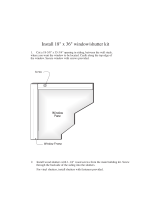
Wall Shield Installation
When horizontally venting directly off the rear of the
stove, install the decorative Wall Shield #129349,
(included in the stove), to cover the top of the
venting hole in the wall. See Figure 14.
1. Remove the top four 1/4” hex head screw from the
rear shroud of the stove.
2. Align the holes in the wall shield with the holes in
the rear shroud.
3. Secure the wall shield to the stove with the four
1/4” hex head screws.
Figure 13. Termination clearances to exterior overhangs.
Rear
Shroud
Wall Shield
Figure 14. Install the Wall Shield.
18 Max.
460 mm
Simpson Dura-Vent
Horizontal Termination
Cap #984 or #985
6 (150 mm)
Simpson Dura-Vent
#908B
Two 90 Degree
Elbows
OPTION # 5
Figure 12-5. Horizontal vent with two elbows.
OPTION # 4
Figure 12-4. Maximum horizontal run with single
elbow to a snorkel termination.
3
76 mm
12
305
mm
2 1/2
64 mm
Two Simpson
Dura-Vent 90
Degree Elbows
#990B
Simpson Dura-Vent Wall
Thimble Cover #940
Simpson Dura-
Vent Horizontal
Square
Termination
#984
Figure 12-5a. Horizontal vent with two elbows.
OPTION # 5
Simpson Dura-Vent
14 Snorkel #982
Simpson Dura-Vent 45
Degree Elbow
#945
12 (300 mm) and 6 (150 mm)
Max. Horizontal Run
into a 14 Snorkel
Both Draft Restrictors Required

14
Vent Termination Requirements
Figure 15. Vent Terminal Clearances - National Fuel Gas Code
A = Clearance above grade, veranda, porch , deck, or
balcony : *12 inches (30 cm) minimum.
B = Clearance to window or door that may be opened:
9 inches (23 cm) minimum. We recommend 12
inches to help prevent condensation.
C = Clearance to permanently closed window:
mimimum 12 inches (30 cm) recommended to
prevent condensation on the window.
D = Vertical clearance to ventilated soffit located above
the terminal within a horizontal distance of 2 feet (60
cm) from the centerline of the terminal: 18 inches
(46 cm) minimum.
E = Clearance to unventilated soffit: 12 inches (46 cm)
minimum.
F = Clearance to outside corner: 9 inches (23 cm) min.
Jøtul N.A. strongly recommends 12 inches (30 cm),
particularlywhere windy conditions are prevalent.
G = Clearance to inside corner: 6 inches (16 cm) min. Jøtul
N.A. strongly recommends 12 inches (30 cm),
particularlywhere windy conditions are prevalent.
H = *Not to be installed above a meter/regulator assembly
within 3 feet (90 cm) horizontally from the center-line
of the regulator.
I = Clearance to service regulator vent outlet: 6 feet (1.8
m) minimum.
J = Clearance to nonmechanical air supply inlet to building
or the combustion air inlet to any other appliance: *12
inches (30 cm) minimum.
K = Clearance to a mechanical air supply inlet: *6 feet
(1.8 m) minimum.
L = ** Clearance above paved sidewalk or a paved driveway
located on public property: *7 feet (2.1 m) min.
M = Clearance under veranda, porch, deck, or balcony: *12
inches (30 cm) minimum.
1
* As specified in CGA B149 Installation Codes. Note: Local Codes and Regulations may require
different clearances.
** A vent shall not terminate directly above a sidewalk or driveway which is located between
two single family dwellings and serves both dwellings.*
1
Only permitted if veranda, porch, deck, or balcony, is fully open on a minimum of two sides
beneath the floor.*

15
Tools Required:
• 1/4” Nut driver
• 7/16” and 1/2” open end wrench
• Torx T-20 or slotted screwdriver.
Fuel Conversion Kit Contents:
• 1 regulator tower labeled for Propane
• 3 regulator tower screws
• 1 burner orifice (#48 for NG, 3/64 for LPG)
• 1 pilot orifice (#51 for NG, #30 for LPG)
• Label A - to be completed and applied to the back
of the stove.
• Label B - to be applied to the stove Rating Plate.
• Small valve label - apply to the Control Valve body.
Conversion instructions are also included in the
conversion kit.
Mobile Home Installation
The Jøtul GF 200 DV Lillehamme can be installed for
use in a mobile home in the U.S. and Canada pro-
vided:
1. The stove is secured to the floor of the mobile
home. Use Jøtul Floor Mounting Kit #154342.
2. The stove is installed in accordance with Title 24
CFR, Part 3280- Manufactured Home Construction
and Safety Standard, in the U.S. Comply with CSA
Z240.4, Gas Equipped Recreational Vehicles and
Mobile Housing, in Canada.
3. Always contact your local building code officials
about installation restrictions and specific require-
ments in your area.
THIS APPLIANCE MAY BE INSTALLED AS
AN OEM INSTALLATION IN A MANUFAC-
TURED (MOBILE) HOME AND MUST BE
INSTALLED IN ACCORDANCE WITH THE
MAUFACTURER’S INSTRUCTIONS AND THE
MANUFACTURED HOME CONSTRUCTION
AND SAFETY STANDARD, TITLE 24 CFR,
PART 3280. THIS APPLIANCE IS ONLY FOR
USE WITH THE TYPE OF GAS THAT IS
INDICATED ON THE STOVE’S RATING
PLATE. A GAS CONVERSION KIT IS PRO-
VIDED WITH THE LILLEHAMMER DIRECT
VENT GAS STOVE.
THIS APPLIANCE MAY BE INSTALLED IN AN
AFTERMARKET PERMANENTLY LOCATED,
MANUFACTURED (MOBILE) HOME, WHERE
NOT PROHIBITED BY LOCAL CODES.
CET APPAREIL PEUT ETRE INSTALLE DANS
UN MAISON PREFABRIQUEE (MOBILE)
DEJA INSTALLEE A DEMEURE SI LES
REGLEMENTS LOCAUX LE PERMETTENT.
CET APPAREIL DOIT ETRE UTILISE
UNIQUEMENT AVEC LES TYPES DE GAS
INDIQUES SUR LA PLAQUE SIGNALETIQUE.
NE PAS L’UTILISER AVEC D’AUTRES GAS
SAUF SI UN KITDE CONVERSION CERTIFIE
EST INSTALLE.
Gas Conversion
The Jøtul GF 200 DV Lillehammer gas stove is
shipped from the factory equipped to burn NATU-
RAL GAS. Install the Fuel Conversion Kit, included
with the stove, if Propane use is necessary. The kit
contains all the necessary components needed for
safe conversion and includes appropriate conversion
notice labels.
WARNING:
THE CONVERSION KIT IS TO BE IN-
STALLED BY AN AUTHORIZED JØTUL
SERVICE TECHNICIAN IN ACCORDANCE
WITH THE MANUFACTURER’S INSTRUC-
TION AND ALL CODES AND REQUIRE-
MENTS OF THE AUTHORITY HAVING
JURISDICTION. FAILURE TO FOLLOW
THESE INSTRUCTIONS COULD RESULT
IN SERIOUS INJURY OR PROPERTY
DAMAGE. THE QUALIFIED AGENCY
PERFORMING THIS WORK ASSUMES
RESPONSIBILTY FOR THIS CONVER-
SION.
Canadian Requirements
THE CONVERSION SHALL BE CARRIED OUT
IN ACCORDANCE WITH THE REQUIREMENTS
OF THE PROVINCIAL AUTHORITIES HAVING
JURISDICTION AND IN ACCORDANCE WITH
THE REQUIREMENTS OF THE CAN1-B149.1
AND .2 INSTALLATION CODE.

16
Gas Conversion Procedure
See Figure 29, page 25 for parts identification.
1. Turn off gas supply to the stove.
2. Remove the stove Top Plate (3).
3. Remove the Front Panel. Using a 10mm open-
end wrench, loosen the two bolts holding the
Front Panel (1) to the side panels (2). (Note: You
do not have to remove these bolts.) Pull the
Front Panel away from the stove and lift off of
Bottom Plate.
4. Release the Glass Retainer Clips (12) on top of
the firebox and carefully lift the Glass Panel up and
out.
5. Remove the Logs (14) using care to avoid chip-
ping or other damage.
6. Lift out the Air Deflector (17). Remove the Air
Divider (16) by lifting right side and slowly
rotating forward.
7..Remove Burner Tube (15): Using a ¼” nut driver,
remove the two screws securing the Burner Tube
to the stove bottom. Lift out the Burner Tube.
WHEN RE-INSTALLING THE BURNER TUBE, BE
SURE THAT THE TUBE IS PULLED FORWARD IN
THE MOUNTING HOLES. Secure with the two 1/
4” screws.
8. Remove the Burner Orifice Holder Shield (18)
around the orifice. Using a 1/4” nut driver
remove the screw attaching the shield to the rear
wall of the firebox. Slide the shield left and
remove.
9. Change the Main Burner Orifice (38). Use a ½”
open end wrench to remove the burner orifice and
replace with the appropriate orifice supplied in the kit.
#48 for Natural Gas
3/64” for Propane
10. Adjust the Air Shutter on the Burner Tube (15)
to allow for the proper mixing of air and gas. See
fig. 16. The correct settings:
Open 1/8” for Natural Gas
Open 3/4” for Propane
11. Change the Pilot Orifice. From within the firebox,
pull the Spring Clip back to release the Pilot Hood
from the Pilot Base. Use the 4m mm hex key to
remove the original Pilot Orifice from the base,
(counterclockwise). See fig. 17.
Install the appropriate pilot orifice:
#51 for Natural Gas
#30 for Propane.
Be certain the orifice is securely tightened. If the
orifice is loose, gas flow will not be properly
regulated.
Replace the Pilot Hood onto the base by re-
engaging the spring clip around its collar.
12. Replace the variable Regulator. Using a Torx T-20
screwdriver, remove the three mounting screws
Pilot Hood
Pilot Orifice
Pilot Base
Spring
Clip
Figure 17. Pilot assembly and orifice.
Figure 16. Air Shutter adjustment and Burner Orifice.
Open 1/8” for Natural Gas
Open 3/4” for Propane
Air Shutter
Burner Orifice
Burner Tube

17
Connect the Gas Supply
The gas supply line connection is made to the valve
just inside the left rear leg. The gas supply line
should be 3/8" npt with a 1/2" diameter supply, or
the appropriate size to provide sufficient gas pres-
sure to the valve regardless of the input setting.
The use of Flexible Gas Appliance Connectors is
acceptable in many areas in the U.S. However,
Canadian methods vary depending on local code.
ALL INSTALLATIONS MUST COMPLY WITH LOCAL
CODE OR IN THE ABSENCE OF LOCAL CODE, MUST
COMPLY WITH THE MOST RECENT EDITION OF THE
NATIONAL FUEL GAS CODE ANSI Z223.1/NFPA 54 OR
CAN-B149.
All codes require a gas shut-off valve (gas cock)
and union, to be installed in the supply line, and in
the same room as the appliance. This allows for the
disconnection of the stove for servicing and mainte-
nance. See Figure 19.
T-HANDLE GAS COCKS ARE REQUIRED IN MASSA-
CHUSETTS IN COMPLIANCE WITH CODE 248CMR.
Secure all joints tightly using appropriate tools
and sealing compounds. For propane units be sure
to use compounds that are propane resistant.Turn
on gas supply and test for gas leaks using a soapy
water solution.
ALWAYS REFER TO THE LIGHTING
INSTRUCTIONS ON THE BACK COVER
OF THIS MANUAL WHEN LIGHTING
YOUR LILLEHAMMER.
Figure 19. Supply Line Shut-off Valve Configurations.
Figure 18. Regulator Assembly.
Mounting
Screws
Regulator Tower
Regulator
Gasket
Conversion
Label
from the front of the valve Regulator. See fig. 18.
13. Remove the regulator tower and the gasket.
14. Install the new variable regulator parts,
confiming that the gasket is properly positioned.
Replace the regulator cover and tighten the three
screws securely.
15. Apply the identification labels to locations as
follows:
• Label A - apply to back of stove.
• Label B - apply to stove’s rating plate.
• Small Conversion Label - apply to valve.
16. Reassemble the stove. Connect supply gas to the
system and check for leaks using a soapy water
solution.
WHEN RE-INSTALLING THE BURNER TUBE, BE SURE
THAT THE TUBE IS PULLED FORWARD IN THE
MOUNTING HOLES AND SECURED WITH THE TWO 1/
4” SCREWS.
NEVER USE AN OPEN FLAME TO
CHECK FOR GAS LEAKS.

18
Leak Test:
• Mix a 50-50 solution of water and dish soap.
• Light appliance- see lighting instructions on page
21 of this manual or on the stove’s rating plate.
• Brush or spray all joints and connections with the
soapy water solution.
If bubbles appear at any connection or seam or a
gas odor is detected immediately turn gas control
knob to the OFF position.
Tighten or reconnect the leaking joint and retest
for any gas leaks.
Gas Pressure
Correct gas pressure is essential for efficient and
safe operation of this appliance. It is important that
the correct pressure is established at the time of the
installation. Proper gas pressure provides a consis-
tent flow of gas to the appliance and is instrumental
in checking for gas leaks.
The gas control valve on the stove is equipped
with pressure test points for gauge connections. It is
possible then to test SUPPLY/INLET pressure and
manifold pressure at the appliance.
Testing the available gas pressure should be
done by attaching a manometer to the appropriate
test point on the valve. The gauge connections are
located on the front of the valve under the On/Off/
Pilot- knob. Gauge connections are identified by:
E - for Inlet or supply pressure (the amount of gas
coming to the valve.)
A - for Manifold pressure (the amount of gas that is
coming out of the valve to the burner.) See fig. 20.
ALWAYS TEST PRESSURES WITH REGULA-
TOR CONTROL KNOB SET ON HIGH.
Required Inlet Gas Pressures (in. W.C.)
MIN. MAX.
NATURAL GAS 5.0 7.0
PROPANE 11.0 13.5
The appliance and its main gas valve must be
disconnected from the gas supply piping system
during any pressure testing on that system at test
pressures in excess of 1/2 psig (3.5kPa).
The appliance must be isolated from the gas
supply line by closing its individual manual gas shut-
off valve (gas cock) during any pressure testing of
the gas supply piping system that is equal to or
exceeds pressures of 1/2 psig (3.5kPa).
Required Manifold Pressure
(in. W.C.)
MIN. MAX.
NATURAL GAS 2.2 3.5
PROPANE 5.5 10.0
Figure 20. Supply and Manifold pressure test points.
A
E

19
Derating Procedure:
To derate this unit, install the appropriate orifice as
shown in the High Altitude chart.
1. Remove the two ¼” hex head screw that holds
the burner tube/log support to the bottom of the
stove.
2. Remove the burner tube/log support to expose
the main burner orifice.
3. Remove the air deflector shield around the main
burner orifice.
4. Remove the orifice and replace with the appropri-
ate one from the high altitude kit.
5. Be sure to attach the high altitude conversion
sticker provided with the kit to the rating plate on
the appliance.
A self-adhesive Conversion Label ( Fig. 21) is
included with the High Altitude Kit. Apply this label
to the control valve after it has been converted for
high altitude.
EPYTSAG
ECIFIRO
EZIS
NOITAVELE
TRAP
REBMUN
LARUTAN
SAG
84#'0002-0
)m016-0(
704921
LARUTAN
SAG
94#
'0054-1002
)m0731-116(
114921
ENAPORP
SAG
46/3
'0002-0
)m016-0(
904921
ENAPORP
SAG
65#
'0054-0002
)m0731-116(
373451
Table 3. High Altitude Orifice Chart.
Figure 21. High Altitude Conversion Label.
High Altitude Adjustment
When installing the Lillehammer in high altitude
(above 2500 ft.) locations, it becomes necessary to
compensate for the thinner air (less volume of oxygen
per cubic foot). High altitudes affect the atmospheric
pressure and heat value of gaseous fuels. The lower
oxygen content in the air and the lower gas viscosity
require the use of a different orifice to achieve
efficient, clean combustion at the burner tube.
U.S. Requirements
THE DERATING KIT MUST BE INSTALLED BY AN
AUTHORIZED SERVICE TECHNICIAN IN ACCORDANCE
WITH THE MANUFACTURER’S INSTRUCTIONS AND ALL
CODES AND REQUIREMENTS OF THE AUTHORITY
HAVING JURISDICTION. THE INFORMATION STICKER
MUST BE FILLED OUT BY THE INSTALLER AND AD-
HERED TO THE APPLIANCE AT THE TIME OF THE
CONVERSION. THE QUALIFIED SERVICE AGENCY
PERFORMING THIS WORK ASSUMES RESPONSIBILITY
FOR THIS DERATING.
Canadian Requirements
This unit has been tested for installation at high
altitudes in accordance with Canadian test standard
CAN/CGA-2.17.
THE DERATING SHALL BE CARRIED OUT IN ACCOR-
DANCE WITH THE REQUIREMENTS OF THE PROVIN-
CIAL AUTHORITIES HAVING JURISDICTION AND IN
ACCORDANCE WITH THE REQUIREMENTS OF THE
CAN1-B-149.1 AND .2 INSTALLATION CODE.
For installations from 610 - 1370 meters (2000-
4500 ft.) the orifice size for natural gas is #49 and for
propane gas #56. SEE THE HIGH ALTITUDE ORIFICE
CHART
See the Rating Plate for additional information.
For high altitude installations, consult the local gas
distributor or the authority having jurisdiction for
proper rating methods. If the installer must convert
the unit to adjust for varying altitudes, the informa-
tion sticker must be filled out by the installer and
adhered to the appliance at the time of the conver-
sion.
THIS STOVE HAS BEEN CONVERTED FOR USE
AT AN ALTITUDE OF ____________________
Orifice Size _______ Manifold Press: ______
Input BTU/Hr. _____ Fuel Type __________
Date of Conversion ____________________

20
Install the Log Set
The Lillehammer is equipped with a one piece log
set and is packaged in bubble wrap inside the
firebox. The log set must be removed from the
packaging and arranged in the unit prior to start up
of the gas stove. Do not handle the log set with
your bare hands. Always wear gloves to prevent
skin irritation from the ceramic fibers.
To install the log set, remove the packaging and
place the log set inside the firebox, centered from
left to right and completely against the rear wall of
the stove. See Figure 23.
A package of Glow Embers is included with the
Log Set. These are to be placed across the burner
tube on the screen. It is best to equally space these
embers for optimum flame appearance. Note: All of
the embers do not have to be used.
Use work gloves to handle the ceramic logs and
and Glow Embers. These parts can irritate skin. If
contact and irritation occurs, gently wash your hand
with a mild soap and warm water.
Air Shutter Adjustment / Flame Picture
The Lillehammer is shipped from the factory
equipped to use NATURAL GAS. When converted for
use with propane gas, the air shutter on the burner
tube must be adjusted to achieve the proper gas to
air mix.
Air Shutter Settings: See Figure 22.
1/8” open for Natural Gas
3/4” open for Propane
The air shutter can also help achieve the desired
flame appearance. Generally, flame appearance is a
matter of preference, however most consumers
enjoy the warm yellowish flame.
Too large a setting - the appliance will generate
a flame that is blue and transparent, or an “anemic”
flame.
Too small a setting - the appliance will generate
very long yellow flames resulting in soot. Sooting
produces black deposits on the logs, on the inside
walls of the appliance, and potentially on the
exterior termination cap.
Sooting is caused by incomplete combustion in
the flames and lack of combustion air entering the
air shutter opening.
To adjust the air shutter, remove the burner
tube and using a phillips head screwdriver loosen
the screw at the air shutter and adjust accordingly.
Be sure to retighten the screw that holds the air
shutter setting. Reassemble the stove and close the
door, allow stove to burn 30 minutes on the HIGH
setting, observing the flame continuously. If the
flame appears weak, slow, or sooty, repeat the process
described above until the flame is as desired.
Recommended Air Shutter Settings:
Natural Gas - 1/8” open
Propane - 3/4” open
WARNING:
AIR SHUTTER ADJUSTMENTS SHOULD
ONLY BE PERFORMED BY A
QUALIFIED PROFESSIONAL SERVICE
TECHNICIAN.
Figure 23. Seat log set against rear wall.
NOTE: Air shutter should never be
LESS than 1/8” open.
Air Shutter
Figure 22. Air shutter opening.
Burner Tube
Locking
Screw
Embers
/