Page is loading ...

1
Sears, Roebuck and Co., Hoffman Estates, IL 60179 U. S. A.
SAVE THIS MANUAL
Reverse Osmosis
Drinking Water System
u Warranty
u How To Install
u How It Works
u Care Of
u Repair Parts
OWNER’S
MANUAL
MODEL NO.
625.347001
Caution:
Read and Follow
All Safety Rules and
Operating Instructions
Before First Use of
This Product.
If you have questions when
installing, operating or
maintaining your reverse
osmosis system, call this
toll--free number...
1--800--426--9345
PRINTED IN U.S.A.

2
-- WARRANTY --
Sears, Roebuck and Co., D/817 WA, Hoffman Estates, IL 60179
For one year from the date of purchase, when theReverse Osmosis Drinking Water System is installed
and maintained in accordance with our instructions,Sears will repair, free of charge,defects in material
and workmanship, except filter cartridges and the R. O. membrane.
TO OBTAIN WARRANTY SERVICE, SIMPLY CONTACT THE NEAREST SEARS SERVICE CENTER
THROUGHOUT THE UNITED STATES. This warranty applies only while this product is in use in the
United States.
Thiswarrantygivesyouspecificlegalrights,andyoumayhaveotherrightswhichvaryfromstatetostate.
FULL WARRANTY ON REVERSE OSMOSIS DRINKING WATER SYSTEM
(except filter cartridges and R. O. membrane)
SEARS INSTALLATION POLICY
All installation labor arranged by Sears shall be per-
formed in a neat, workmanlike manner in accor-
dance with generally accepted trade practices. Fur-
ther, allinstallations shall complywithall locallaws,
codes, regulations, and ordinances. Customer shall
also be protected, during installation, by insurance
relating to Property Damage, Workman’s Com-
pensation and Public Liability.
SEARS INSTALLATION WARRANTY
In addition to any warranty extended to you on the
Sears merchandise involved, which warranty be-
comeseffectivethedatethemerchandiseisinstalled,
should the workmanship of any Sears arranged
installation prove faulty within one year, Sears will,
upon notice from you, cause such faults to be cor-
rected at no additional cost to you.
-- SAFETY GUIDES --
B Read all steps, guides and rules carefully before
installing and using your reverse osmosis system.
Follow all steps exactly to correctly install. Reading
this manual will also help you to get all the benefits
from the reverse osmosis system.
B Donotattemptto use this product to make safe
drinkingwaterfromnon-potablewatersources.Do
notuse thesystem onmicrobiologically unsafewa-
ter, or water of unknown quality.
B Checkwithyourlocalpublicworksdepartment
for plumbing and sanitation codes. You must fol-
low their guides as you install the system. Follow
your local codes if they differ with guides in this
manual.
B Thereverseosmosissystemworksonwaterpres-
sures of 40 psi (minimum) to 125 psi (maximum). If
your house water pressure is over the maximum,
install apressure reducingvalve inthe watersupply
pipe to the reverse osmosis system.
B Do not install the reverse osmosis system out-
side,orinextremehotorcoldtemperatures.Temper-
atureof thewater supplytothereverse osmosis sys-
tem must be between 40_F and 100_F. Do not install
on hot water.
B Read the other limits (pH, hardness, etc.) in the
specifications and be sure your water supply con-
forms. Also see “Water Supply” on page 3.
B The reverse osmosis membrane contains a pre-
servative forstorageandshipment.Besuretopurge
as instructed on page 9 beforeusing productwater.

3
-- TABLE OF CONTENTS --
Where To Install the RO System . . . . . . . . 4
Tools and Materials Needed . . . . . . . . . . . 4
Installation Steps . . . . . . . . . . . . . . . . . . . . 5-9
Cold Water Supply Saddle Valve . . . . . 5
Drain Adapter . . . . . . . . . . . . . . . . . . . . . 6
Faucet . . . . . . . . . . . . . . . . . . . . . . . . . . . . 6-7
RO Assembly . . . . . . . . . . . . . . . . . . . . . . 7
Storage Tank, Tubing Connections . . . . 8
Installation Steps - continued
Sanitizing, Pressure Test, Purging . . . . 9
How the RO System Works . . . . . . . . . . . 10
Care of RO System . . . . . . . . . . . . . . . . . . . 11-14
Dimensions, Specifications . . . . . . . . . . . . 15
Repair Parts . . . . . . . . . . . . . . . . . . . . . . . . . 16-17
Remote Installation Locations . . . . . . . . . 18
-- WHAT YOUR REVERSE OSMOSIS SYSTEM WILL DO --
Your Reverse Osmosis (RO) Drinking WaterSystem
is a water treatment unit. It uses household water
pressure to reverse a natural physical process called
osmosis. Water, under pressure, is forced through a
semi-permeable membrane where minerals and im-
puritiesarefilteredout.Cleandrinkingwatergoesto
the faucet or storage, while minerals and impurities
aresenttothedrainwithROwastewater.Theminer-
als andimpurities are measured in water as total dis-
solved solids (TDS).
The system includes replaceable pre and postfilter
sediment-carbon cartridges. The prefilter removes
sand, silt, dirt, rust particles, other sediments, and
chlorinefromthewatersupplybeforeitcanenterthe
RO membrane. The postfilter removes any tastes
and/or odors that may remain in the water, after
passing through the RO membrane, and just before
going to the RO faucet. To prevent water waste, an
automaticshutoffvalvecloseswhentheROfaucetis
closed and the storage tank is full.
Yourreverseosmosissystemgivesyouacontinuous
supply of sparkling clear, delicious water for drink-
ing, cooking and other uses. Foods will look and
tastebettertoo.HavinghighqualityROproductwa-
ter at your fingertips eliminates the need to buy
bottled water. The storage tank holds over 2 gallons
of RO product water for your needs.
-- BEFORE YOU BEGIN TO INSTALL THE RO SYSTEM --
Check Your Water Supply: The cold water supply to
the RO system must be within certain qualitylimits.
Seethespecificationtableonpage15.Ifsupplywater
is not within limits, the RO system can not make
product water as it should and reduced RO mem-
brane life will result.
Trained salespeople at Sears can arrange for a free
wateranalysis. Theanalysis willtell youif otherwa-
ter supply treatment is needed before going to the
RO system.
CAUTION:Chlorineinthewaterwilldestroythe
ROmembrane.Mostcities add chlorineto thewa-
ter supply to kill bacteria. The prefilter removes
chlorineuptothelimits showninthespecifications
before it enters the RO membrane. It is important
to replace the prefilter cartridge at least every 6
months. See the RO care guide on page 14.
Check Parts Included: Unpack the carton and re-
move the RO system. In addition to the assembled
RO and the storage tank, the system includes the
parts illustrated below, a separate length of tubing,
and this manual.
DRAIN
ADAPTER
RO PRODUCT
WATER FAUCET
WATER SUPPLY SADDLE VALVE
TUBING
ADAPTERS
FIG. 1
HANGER
WASHERS &
SCREWS

4
-- WHERE TO INSTALL THE RO SYSTEM --
The RO assembly and storage tank is designed for
installation under the sink, usually in the kitchen or
bathroom. The RO assembly mounts on a wall sur-
face,orcanlayonthecabinetfloornexttothestorage
tank.Hangerwashersandwoodscrewsareincluded
for cabinet wall mounting. The RO product water
faucet installs on the sink, or on the countertop next
to the sink (pages 6 and 7).
Note: Tubing lengths allow for the removal of the
assemblyfromthehangerwashersfor servicing.If
tubing lengths are shortened for neater appear-
ance, it may be necessary to keep the assembly on
the hanger washers for service.
YoucanalsolocatetheROassemblyandstoragetank
in any remote location from the faucet, observing
safety guides on page2. Youdo needa nearbywater
source and drain point (see page 18).
Water Supply: To provide supply water to the RO
system inlet, a saddle valve is included to install
(wherecodes permit)onacoldwaterpipe,page 5.Pro-
videotherpipefittingsfortubingconnection,astypi-
cally shown on page 5, where saddle valves are not
allowed.
Drain Point: A suitable drain point is needed for re-
ject water from the RO membrane. A floor drain,
laundry tub, standpipe, sump, etc., is preferred, as
shown in the remote locations drawing, page 18. A
sinkp-trapdrainadaptorisincludedtoinstallwhere
codes permit, as an optional drain point (page 6).
cold water
supply
RO product
water faucet
COLDHOT
Storage
Tank
RO Assembly
sink drain
p---trap
drain adapter
FIG. 2
-- TOOLS AND MATERIALS NEEDED --
" adjustable wrench, standard pliers, and larger
adjustable jawpliers or pipe wrench to fit sink drain
" slotted and Phillips head screwdrivers
" plumbers putty
" pipejointcompound(threadseal)orTeflontape,
approved for use on potable water supplies
" hand or battery powered drill with 1/8” bit (if
needed for the cold water supply valve, page 5)
" electricdrillandbits,ifholeis neededfortheRO
faucet, page 6 and 7
-- 6 STEPS TO INSTALL --
STEP1: - InstallColdWaterSupplySaddleValve,or
other fittings - page 5
STEP 2: - Install Drain Adapter - page 6
STEP 3: - Install Faucet - pages 6 and 7
STEP 4: - Install RO Assembly - page 7
STEP5:- InstallStorageTank,MakeRemainingTub-
ing Connections - page 8
STEP 6: - Sanitizing, Pressure Testing, Purging -
page 9

5
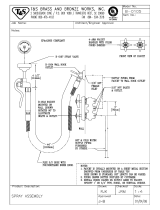
-- STEP 1: INSTALL COLD WATER SUPPLY SADDLE VALVE --
Checkandcomplywith local plumbing codes as youplan,theninstallacoldfeed(supply)waterfitting. The
fitting must provide a leak-tight connection to the RO 1/4” tubing (see FIG. 8,page 8).A typicalconnection,
using theincluded saddlevalveis showninFIG.3 -A below.An optional connection,usingstandardplumb-
ing fittings (not included), is shown in B.
Note:CodesinthestateofMassachusettsrequireinstal-
lation by a licensed plumber, and do not permit the use
of the saddle valve. For installation, use plumbing
code 248-CMR of the Commonwealth of Massa-
chusetts.
A. SADDLE VALVE
Note: This valve has a cutting pin and will pierce a
holeincoppertubingorplasticpipe.Ifinstallingon
ironpipe,youhavetodrilla1/8”holeforthepierc-
ing pin. Read the following danger note and be
suretoturnoffwatertothepipeandtodrainwater
from it before drilling.
DANGER(if drillingmetalpipe):Toprotectyour-
selffromseriousinjuryorfatal shock,useabattery
powered hand drill only to make the hole. Do not
use an electric drill.
1.Closethehousemainwatershutoffvalveandopen
faucets todrain water fromthe sinkcold waterpipe.
2. Observing above note and caution, drill the 1/8”
diameter hole in iron pipe.
3. Looking at figure 3A, turn the valve into clamp X
and tighten (maybe already assembled). Turn the
valve handle all the way out.
4. Place the seal on the inside of clamp X as shown.
Be sure the cuttingpin does not stickoutbeyondthe
seal.
5.PlaceclampXandZaroundthepipeandsecurein
place with 2 screws. If you predrilled a 1/8” hole,
align the cutting pin with it. Tighten both screws
evenly, but do not overtighten. Clamp Z will either
have threaded screw holes, or 2 nuts are included.
6. Carefully turn the handle inward to pierce a hole
in the copper or plastic pipe.
B. OPTIONAL PIPEFITTINGS (compressiontype
shown)
Note: Be sure to turn off the water supply andopen
a low faucet to drain the pipe.
Complying with plumbing codes, install a fitting on
thekitchencoldwaterpipetoadapt1/4” ODtubing.
A typical connection is shown in figure 3B. If
threaded fittings are used, be sure to use pipe joint
compound or Teflon tape on outside threads.
handle
clamp X
clamp Z
nut (2) --- not req’d
with all types of
clamp Z
seal
pre---drill
1/8” hole
for iron pipe
cold water
shutoff
valve
Checklocal
codes for
approval
nut
insert
ferrule
A. WATER SUPPLY CONNECTION
(using included saddle valve)
B. WATER SUPPLY
TYPICAL CONNECTION
(using compression fitting)
ferrule
insert
1/4” compression
fitting
cold
water
pipe
1/4” tubing to
RO inlet (see step
2, on page 8)
use to connect
tubing, step 2,
on page 8
FIG. 3
-- parts not included --
See note on codes
in the state of
Massachusetts,
above left.

6
-- STEP 2: INSTALL DRAIN ADAPTER --
J Note: Running the draintubing directly to afloor
drain, sump, standpipe, laundry tub, etc., as shown
on page 18, is preferred. However, if that is not pos-
sible or practical, the included drain adapterinstalls
in the sink drain pipe, always above or ahead ofthe
p-trap (FIG. 4). Be sure to comply with your local
plumbing codes. Other drain pipe fittings, in addi-
tion to the adapter, may be needed.
J The drain adapter fits 1-1/2” sink drain pipe.
J Theadapterinstallsdirectlyontothesinktailpiece
as typically shown in FIG. 4 and 5.
J Locatesodraintubingfromthefaucet(installedin
step 1, page 8) makes a straight run to the adapter,
without dips, loops, low spots or kinks.
Note: Consult a plumber if you are not familiar
with plumbing procedures.
1. Use aferrule and nutto assemblethe draintubing
connectortothedrainadapter(FIG.5).Turnthecon-
nectortoabout45_ fromthe12:00position,asshown
(to 10:00 or 2:00 position as needed). Tighten the nut
securely.
2. Carefully disassemble the sink drain pipe and
clean the tailpiece to assure a leak-tight fit.
3. Install the drain adapter onto the sink tailpiece,
using a ferrule and nut. Snug the nut, but do not
tighten.
Note: If needed, to make fit, you can cut toshorten
the unthreaded end of the adapter. Do not cut too
shortsotheadapterwillmakealeak-tightsealwith
the connecting fitting.
4.Assemblethep-traptothedrainadapter,andoth-
er drain pipe fittings as required (check codes) to
complete the drain run.
5.Tightenallconnections,butdonotovertightenand
break plastic fittings.
FIG. 4
A B
drain
adapter
45_
sink tailpiece
drain adapter
ferrule
ferrule
nut
nut
drain tubing
connector
FIG. 5
2:0010:00
45_
black
collet
cut, if
needed
-- STEP 3: INSTALL FAUCET --
A. PREPARE MOUNTING HOLE
1. Select 1 of the following places for the faucet. Be
sure it will fit flat against the surface, and there is
space underneath for tubing (see FIG. 8, page 8).
' Use an existing sink top hole for a spray hose or
other faucet. A 1” to 1-1/4” diameter hole is need-
ed.
' Drill a new hole in the countertop next to the
sink.
' Drill a new hole in the sink top.
CAUTION: To avoid damaging a sink beyond re-
pair, consult a qualified plumber or installer for
guides to drill holes in porcelain or stainless steel.
2. If drillingis needed,make the 1” to 1-1/4” diame-
ter hole.
3.Placeplumbersputtyaroundthedrilledhole(FIG.
6) to prevent water leakage around the base of the
faucet.

7
-- STEP 3: INSTALL FAUCET (cont.)--
B. ASSEMBLE FAUCET
1.Ifnotalreadyassembled,installtherubberwasher,
spacer, flat (or lock) washer and hex nut onto the
threaded faucet stud.
2. Apply Teflon tape to the end of the faucet stud.
Turn the tubing adapter with a blue collet onto the
stud and hand tighten, then wrench 1/4 turn only.
BE CAREFUL NOT TO CROSS THREAD.
3. Wet the o-ring seals on the faucet spout. Then, re-
move and discard the short piece of tubing from the
faucet body and insert the spout in it’s place.
4. CONNECTTUBINGTOFAUCET ASFOLLOWS.
a. Take the separate length of 3/8” black tubing
and,puttingendthroughthelargerholeintherub-
berwasher,slideendontothelargerbarbfittingon
the bottom of the faucet.
Note:Tosoftenendoftubing,holdunderhotwater.
b. Route 1/4” red tubing from RO up through the
sinkholeandslideendontothesmallerbarbfitting
(heat end if needed) on the faucet.
c. Route 3/8”blue tubingfromROup throughthe
sink hole and push end allthe wayinto thetubing
adapter fitting on the bottom of the faucet. Pull on
the tubing to besure it’s held firmlyin theadapter
fitting. See pages 12 and 13 for tubing connection
instructions.
5. Lower the faucet into the sink or countertop hole.
6. On the underside of the sink or countertop, insert
the large steel washer between the mounting hole
and the spacer on the faucet stud (see assembled
view). Then, turn the hex nut up to the spacer and
tighten. Tighten the hex nut so the faucet can not
move, but do not overtighten and break thefaucet.
-- STEP 4: INSTALL RO
ASSEMBLY --
Hangtheassemblyontheincluded hangerwashers,
or lay on the cabinet floor, as desired.
1.RefertoFIG.7forwallmounting.Holdtheassem-
bly up to thewall surface and marklocations for the
hangerwashers.Indicatormarksontopofthebrack-
et are the needed 10-1/2” apart.
2.Installhangerwashersatleast15-1/2” upfromthe
cabinet floor, allowing room to remove sumps from
filter heads. Wood screws are provided, or obtain
other fasteners as needed.
FIG. 7
ASSEMBLED IN
MOUNTING HOLE
faucet & spout
rubber washer
spacer
flat (or lock)
washer
hex nut
tubing adapter
plumbers putty
hole in sink or
countertop
steel washer
tubing barb
fittings
remove tub-
ing piece
insert spout
TUBING FROM
RO SYSTEM
1/4” red tubing
from RO drain
3/8” blue
tubing
3/8” black tubing
to drain point
steel washer
spacer
hex nut
10-1/2”
FIG. 6
hanger
washer (2)
screw (2)
15-1/2”
min.
up from
floor
blue collet
10-1/2” indicators

8
-- STEP 5: INSTALL STORAGE TANK,
MAKE REMAINING TUBING CONNECTIONS --
1. CONNECT DRAIN TUBING, FAUCET TO
DRAINADAPTER:ReferringtoFIG.8,runtheloose
section (connected to faucet barb fitting) of black
3/8” tubingfromthefaucettothedrainadapter,with
a black collet, installed on page 6. Cut this tubing as
needed to route in as straight of a run as possible,
withoutloops,dips,lowspotsor kinks.Cuttheend
of the tubing square. Then, push allthe way intothe
fitting. Pull on the tubing to be sure it’s held firmly
in the adapter fitting.See pages 12 and13 fortubing
connection instructions.
2.CONNECTTUBINGTOWATERSUPPLY:Usethe
tubinginsert,ferruleandnuttofastenthe1/4” green
tubingtothesaddlevalvefitting installedonpage5.
Tighten the nut with a wrench.
3.MovethestoragetankintoplacenexttotheROas-
sembly. You can stand the tank upright, or lay it on
side. Apply no more than 2 wraps of Teflon tape to
thethreadsonthenippleatthetopofthetank.Hand
tighten, then wrench 1/4 turn only, the other in-
cluded tubing adapter fitting with the yellow collet
ontothetanknipple. BECAREFULNOTTOCROSS
THREAD.
4. Run the 3/8” yellow tubing to the fittinginstalled
in step 3. Be sure the end of the tubing is cut square,
and insert all the way intothe fitting.Again, pullon
the tubing to be sure it’s held firmly in the fitting.
water supply
valve
drain adapter
sink p---trap
RO product
water faucet
COLDHOT
3/8” black tubing, to
larger barb on faucet
TYPICAL UNDERSINK INSTALLATION
OPEN
CLOSE
insert
ferrule
nut
FIG. 8
yellow collet
tubing adaptor
Note: See note on page 4
regarding tubing lengths.
See note on
codes in the state
of Massachusetts,
page 5.

9
-- STEP 6: SANITIZING, PRESSURE TESTING & PURGING --
SANITIZING
Sanitizing is recommended upon installation of the
RO system, and after servicing inner parts. It is im-
portant for the service person to have clean hands
while handling inner parts of the system.
CAUTION: Be sure to remove the RO membrane
andboth filtercartridges asfollows,beforesanitiz-
ing. Chlorine will destroy the RO membrane car-
tridge.
1. Be sure the water supply to the RO is turned off,
and the RO faucet is open to relieve pressure.
2. Referring to FIG. 9, page 11, press inward while
turningtheROcaptotheleft(?)toremovefromthe
bracket/membrane housing. Remove (use pliers)
the RO cartridge from the housing. Place the car-
tridge in a clean plastic bag.
3.Besuretheo-ringsealis intheROcap.Replacethe
RO cap and push inward while turning to the right
(?) to lock.
4. Remove the postfilter sump, turning to the left.
Take the cartridge from the sump and place in the
plastic bag. Replace the sump and tighten securely.
5. Remove the prefilter sump and cartridge. Also
place this cartridge in the clean bag.
6. If needed to clean, flush the prefilter sump with
freshwater.Then,fillwithwatertoabout1”fromthe
top. Add 1.0 ounce of chlorine (ordinary 5.25%
householdbleach...Hilex,Clorox,etc.)andmixinthe
water. Do not add chlorine first. Concentrated, it
will attack plastics.
7. Carefully replace the sump on the prefilter head
and tighten securely.
8. Slowly open the water supply to the RO.
9. Open the RO faucet, locking the lever upward,
against the spout.
10. Allow water to circulate through the RO system
untilyou smellthebleachodor.Thenclosethefaucet
and allow the RO to stand idle for 20 minutes.
11.Afterthe20minutes,openthe ROfaucet andrun
water until the bleach odor is gone.
12. Turn off the water supply to the RO.
13. Be sure your hands are clean. Then, repeat steps
1 - 5 and 7, only replace all cartridges.
Important: Refer to FIG. 9, page 11, and to page 12
when replacing cartridges. The prefilter (left side)
cartridge has lightgray coloring, and thepostfilter
(right side) has blue coloring.
PRESSURE TESTING
1. Do the preceding sanitizing procedures before
pressure testing.
2. Open the water supply shutoff valve to the RO.
3. Open the main water supply valve and several
house faucets to purge air from the system. Close
faucets when water runs smooth.
4. In about 2 hours, pressure will start to build in the
ROsystem.Then,carefullycheckallfittingsandcon-
nections for water leaks. Correct leaks if any are
found.
Note: When the system is first pressurized, water
may‘‘spurt’’fromthefaucetairgapholeuntilairis
expelled from the RO system.
PURGING RO MEMBRANE
Important purging instructions: The RO cartridge
contains a food grade preservative that you should
cleanfromitbeforeusingwaterfromthesystem.The
preservative will give product water an unpleasant
taste and odor.
1. Allow the storage tank to fill for about 4 hours.
Then,opentheROfaucetuntilthetankisemptyand
flow stops.
2.ClosetheROfaucetandallowthetanktofillagain
for 4 hours. Then, open the RO faucet and empty
again.
Repeatsteps1and2topurgethestorage tank 4 times.Then, theRO system is ready to
make product water for use.

10
-- HOW YOUR REVERSE OSMOSIS SYSTEM WORKS --
PREFILTER
Water from the cold supply pipe enters the RO as-
sembly prefilter first (FIG. 8 and schematic below).
The prefilter has a replaceable sediment cartridge
with activated carbon in its composition. The car-
tridge(10micron)removessand,silt,dirt,othersedi-
ments, and up to the ppm of chlorine shown in the
specifications fromthefeed water.Chlorinewill de-
stroy the RO membrane. Filtered, clean, chlorine-
free water flows from the prefilter, to the RO mem-
brane cartridge.
IMPORTANT: See prefilter maintenance, page 11.
REVERSE OSMOSIS (RO) CARTRIDGE
The cartridge inside of the RO housing, is a tightly
wound, special membrane. Water is forced through
the cartridge and the membrane removes the dis-
solved solids andorganicmatter.Highqualityprod-
uct water (about 1 ounce per minute) exits the RO
housing and goes to the storage tank, orto thepost-
filter andRO faucet.Reject water,withthedissolved
solids andorganicmatter,is routedthroughtheflow
control and to the drain.
STORAGE TANK
The storage tank holds up to 2.3 gallons of product
water. A diaphragm inside the tank keeps water
pressurized to about 30 psi, when the tank is full, to
providefastflowfromtheROfaucet.Thetank,when
empty, is pressurized to 5 - 7 psi.
POSTFILTER
Afterleavingthestoragetank,butbeforegoingtothe
ROfaucet,productwatergoesthroughthepostfilter.
The postfilter is an activated carbon type filter. Any
remaining tastes and odors are removed from the
product water. Taste-free, odor-free, clean, high
quality drinking water is available for use.
FAUCET
The sink or countertop faucet has a hand operated,
spring-loaded closed lever to prevent the waste of
drinkingwater.You canalsokeepthefaucetopenby
pushing upward on the lever and locking it against
the faucet spout.
To comply with plumbing codes, an air-gap is built
into the faucet drain water connection.
SHUTOFF ASSEMBLY
Toconservewater,thedrinking watersystem has an
automaticshutoffsystem.Whenthestoragetankhas
filled to capacity, and the drinking water faucet is
closed, pressure closes the shutoff to stop flow into
the RO. Pressure in the storage tank is about half of
the water supply pressure. After drinking water is
used, and pressure in the system drops, the shutoff
opens to allow water flow again.
CHECK VALVE
A check valve (FIG. 10)is locatedin theoutlet endof
theRO housing,oppositeofthecap.Thecheckvalve
prevents a backwardflow of productwater fromthe
storage tank.AbackwardflowcouldrupturetheRO
membrane.
FLOW CONTROL
Water flow through the RO membrane is regulated
bytheflowcontrol.Itmaintainsthedesiredflowrate
to obtain the highest quality drinking water. The
flowcontrolislocatedintheendofthe1/4”reddrain
tubing, at the RO housing drain port. A small cone-
shaped screenfits overthe end of theflow control to
help prevent plugging with drain water sediments.
PREFILTER
PRODUCT
WATER
STORAGE
RO MEMBRANE
check
valve
drain flow
control
AUTOMATIC
SHUTOFF
WATER
IN
POSTFILTER
PRODUCT
WATER
FAUCET
air gap
gravity
drain
REVERSE OSMOSIS
SCHEMATIC
RED
YELLOW
BLUE
GREEN
PRODUCT WATER

11
-- CARE OF YOUR REVERSE OSMOSIS SYSTEM --
To keep your reverse osmosis system operatingand
makinghighqualitywater,youmustmakesuresup-
ply water is always within the limits shown in the
specifications. Good supply water helps to assure
longerlifefromtheROmembranecartridge,prefilter
andpostfiltercartridges.However,eachofthesewill
wear out in time and need replacement.
This reverse osmosis system contains a replaceable
treatment component critical for effective removal of
total dissolved solids. The water should be tested
periodically to verify the system is performing satis-
factorily.
IftheROassemblyiswallmounted,youmaybeable
to replaceparts withthe assemblyleft onthe wall.If
not, simply lift the RO assembly from the mounting
washers and lay on the cabinetfloor whenreplacing
the prefilter and post filter cartridges and RO mem-
brane.
Note: To prevent spillage, place a container under
the RO assembly, or put the RO assembly in a con-
tainer to catch the water.
CAUTION:Beforedisconnectingparts,besureto
close the water supply valve to the RO.
PREFILTER AND POSTFILTER
CARTRIDGES
You must replace the prefilter cartridge often to pro-
tect the RO membrane from being destroyed by chlorine,
and/orfrompluggingwithsediments inyourwater
supply. If the water supply contains both chlorine
andsediments, replacetheprefiltercartridgeatleast
every 6 months of product water use. Replace more
often than 6 months if it begins to plug with sedi-
ments.
Ifthewaterhassedimentsonly,withnochlorine,you
may notice a slower making of product water as the
prefiltercollects thesediments.Whenthis occurs,re-
place the prefilter cartridge. Also replace the postfilter
cartridge.
To replace the filter cartridges (see FIG. 9):
1.TurnoffthewatersupplyandopentheROfaucet
to relieve pressure.
2.Remove(turntotheleft)bothsumpsfromthefilter
heads. Be careful . . .the sumps are full of water.
3.Removeanddiscardtheinnercartridgesinaprop-
er manner. Flush the insides ofthesumps withfresh
water. Do not lose the large o-ring seals.
4.Insertnewcartridges,andwithlubricated*o-rings
in place, turn on and tighten the sumps.
Note: The prefilter cartridge has light gray netting
andendcaps.Thepostfilterhasblue.Donotinter-
change.
*Note:Usealubricantapprovedforuseonapotable
water supply.
RO Cartridge
postfilter
cartridge
(blue)
o--ring
seal
sump
prefilter
cartridge
(lt. gray)
Turn sumps in the
direction of the arrow
to remove. Turn
opposite way to install
and tighten.
o--ring seal
RO cap
mounting
washers (2)
FIG. 9
(RO cartridge
o--ring seals on
this end)
RO MEMBRANE CARTRIDGE
The life of the RO membrane cartridge depends
mostly onthe pH of the supply water tothe ROsys-
tem(seespecifications).Cartridgelifeisshorterwith
higher pH. For example, if supply water pH is from 6.8
to7.7,thecartridgemaylastforwellover1year.However,
cartridge life may be as short as 6 months if the pH is as
high as 8.5 to 10. Higher pH weakens the cartridge
membrane and causes pin-hole leaks.
It’s time to replace the RO cartridge when the pro-
duction rate and/or quality of product waterdrops.
Productwatermaybegintotastedifferentorbad,in-
dicating solids and organics arepassing throughthe
RO membrane. To be sure it is the RO cartridge, re-
place the prefilter and postfilter cartridges first.
To replace the RO cartridge (see FIG. 9):
1.TurnoffthewatersupplyandopentheROfaucet
to relieve pressure.
continued

12
-- CARE OF YOUR REVERSE OSMOSIS SYSTEM --
2. Press inward while turning the RO cap to the left
(?)toremovefromthebracket/membranehousing.
3. Use a pliers, or heavy wire made into a hook, to
pull the RO cartridge from the housing.
Note:Sanitizingis recommendedafter servicingin-
ner parts of the system (see page 9).
4. Install the new cartridge, end with o-ring seals in-
ward. Work back and forth to get all theway in(end
of cartridge about 1-1/4” in from end of housing).
5.LubricatetheROcapo-ringsealifdry.Replacethe
o-ring into the cap. Press inward on the cap while
turningtotheright(?)tolock.Thecapwillnotgoon
if the RO cartridge is not fully seated inward.
6. Check the flow control and screen (see below).
7. Purge the RO membrane cartridge following instruc-
tions on page 9.
FLOW CONTROL AND SCREEN
The flow control is vital for proper operation of the
RO membrane cartridge. The control keeps water
flowthroughthemembraneattheneededratetoob-
tain the best quality product water.
Whenever servicing the RO system, check the flow
control to be sure the small hole through it is clean
andunrestricted.Alsocheckandcleanorreplacethe
cone-shaped screen in front of the control. The RO
membrane cannot discharge minerals and impuri-
ties tothedrainiftheflowcontrolplugswithforeign
material.Ifthishappens,itonlytakesashorttimefor
the membrane to foul and become useless.
To clean/replace flow control and screen (FIG. 10):
1. At the drain connection, depress the collet (FIG.
11) witha finger while carefully pulling on thedrain
tubing to remove.
2. Remove the flow controlfromthe end of thedrain
tubing. Be sure the center hole is clean.
3. Check the drain tubing to be sure it’s clean. Then,
insertthecleanedornewflowcontrolintothetubing.
4.Withasmallscrewdriver, carefullyremovethecol-
let and o-ring from the drain port. Use a small need-
le-nose pliers or tweezers to removethe screenfrom
the drain port. Thoroughly clean, or replace with a
new screen. Install, pointed end down.
Note: Visually check to be sure it is positioned cor-
rectly.
5. Inspect the o-ring and collet. Replace if worn, cut
or otherwise damaged. Carefully replace into the
drain port.
6. Be sure the flow controlis intheendof thetubing,
then push all the way into the fitting.
flow (control) insert
screen
1/4” tubing
check
valve
TO
DRAIN
FIG. 10
cap
o-ring
spring
ball
drain port
o--ring seal
collet
TUBING CONNECTION
(all push-in fitting locations)
This RO system includes push-in fittings for quick
tubingconnection atmostlocations.If workingwith
the fittings, do the following.
Connection (FIG. 11):
1. Use asharpcutter orknife tocut theend oftubing
square.
2. Inspect the end (about 1”) of the tubing to be sure
there are no nicks, scratches or other rough spots. If
needed, cut the tubing again.
3.Pushtubingthroughthecolletandallthewayinto
fitting. Full engagement is 11/16” for 1/4” tubing,
and 3/4” for 3/8” tubing.
continued

13
-- CARE OF YOUR REVERSE OSMOSIS SYSTEM --
TUBING CONNECTION (continued)
If tubing is used, other than supplied with the sys-
tem,besureitisofhighquality,exactsizeandround-
ness with a smooth surface.
To Disconnect Tubing: Push the collet inward and
hold with a finger while pulling the tubing out.
collet (depress to
remove tubing)
tubing
FIG. 11
o--ring seal
collet
fitting
Pusho-ringsealinto
bottom of port, then
follow with collet.
Replacing collet and
o-ring seal
cut tubing square
collet
Tubing correctly cut and connected
11/16” (1/4” tubing)
3/4” (3/8” tubing)
engagement
end of tubing round and
smooth, with no cuts,
nicks or flat spots
Changing Collet and O-ring (FIG. 11):
1. With asmallscrewdriver,removethe collet and o-
ring from the fitting.
2. Be sure the port is clean, then lubricate and insert
the o-ring seal to the bottom of the port.
3. Push the collet inward until it locks in place.
CAUTION
DO NOT USE VINEGAR, OR OTHER ACID
BASEDCLEANERSONTHISROSYSTEM.THEY
WILLDEGRADE SOMEROSYSTEMPARTS.AL-
WAYS USE SOAP AND WATER.
Thisreverseosmosissystemcontains areplaceable
treatmentcomponent critical for effectiveremoval
of total dissolved solids. The water should be
testedperiodically toverifythesystem isperform-
ing satisfactorily.
AUTOMATIC SHUTOFF SERVICE
If the shutoff assembly requires service, be sure to
reassemble parts exactly as shownin FIG. 12, andto
reconnect tubing as shown on pages 10 and 16.
diaphragm
diaphragm
plunger
screw (4)
SHUTOFF
ASSEMBLY
Elbowfittingturns
into OUT port.
collet
Male Elbow,1/8”
NPT x 1/4” Tubing
Male Connector,
1/8” NPT x 1/4” Tube
Tee Fitting,
1/4” NPT x 3/8”
Tube
FIG. 12
tubing

14
-- CARE OF YOUR REVERSE OSMOSIS SYSTEM --
REVERSE OSMOSIS SYSTEM CARE GUIDE
MODEL NO. 625.347001
1. AT LEAST every 6 months, replace the prefilter and postfilter cartridges. Clean or replace the flow control and
screen.
2. Replace the ROmembrane cartridgewhen thepercent rejectionof totaldissolved solids(TDS) isless thanshown
in the specifications (see B, below).
If any of the following occur before the 6 months, replace as directed.
A. Slow Making of ProductWater: Replace the prefiltercartridge.
If the production ratedoes notimprove, replacethe postfiltercar-
tridge and RO membrane cartridge.
C.ChlorineTasteand/orOdor:Replacetheprefilter,postfilterand
RO membrane cartridges.
B. High Total Dissolved Solids (TDS) in Product Water: You can
get a free TDS test through some Sears retail stores or service
departments. If the store or service department does not have a
TDSmeter, you cansend treatedand untreatedwater samplesto
a water analysis lab for testing. It is important to test both the
treated and untreated waterto determinesystem performance. If
the TDS is not within the system’s performance guidelines,
replace the prefilter, postfilter and RO membrane cartridges.
OTHER TROUBLESHOOTING
PROBLEM CAUSE CORRECTION
Chlorine taste and/or
odor in the RO product
water
The ppm of chlorinein yourwater supply
exceeds maximum limits, and has de-
stroyed the RO membrane.
Ifthewatersupplycontainsmorethan2.0ppmofchlorine,addi-
tional filtering of the water supply to the RO is needed. Correct
this condition before doing maintenance on the RO system.
The prefilter is no longer removing chlo-
rine from the water supply.
Replace the prefilter, postfilter and RO membrane cartridges,
flow control, and screen.
Other taste and/or odor Postfilter expended. Replace the postfilter cartridge. If taste and odor persists, re-
p
l
a
c
e
t
h
e
p
r
e
f
i
l
t
e
r
c
a
r
t
r
i
d
g
e
,
R
O
m
e
m
b
r
a
n
e
c
a
r
t
r
i
d
g
e
,
f
l
o
w
c
o
n
-
RO membrane cartridge expended.
p
l
a
c
e
t
h
e
p
r
e
f
i
l
t
e
r
c
a
r
t
r
i
d
g
e
,
R
O
m
e
m
b
r
a
n
e
c
a
r
t
r
i
d
g
e
,
f
l
o
w
c
o
n
-
trol, and screen.
Contamination in product water storage. Use sanitizing procedures. Replace the postfilter cartridge.
System makes product
water too slowly
Watersupply tothe ROsystem notwithin
specifications.
Increasewaterpressure,preconditionthewater,etc.,asneeded
to conform before doing maintenance on the RO system.
Prefilter or RO membrane cartridges
plugged with sediments.
Replace the prefilter cartridge.If ratedoesnot increase,replace
the postfilter cartridge, RO membrane cartridge, flow control,
and screen.
System makes lower
amount of product water
than usual
Storage tank air-charge less than 5 --- 7
psi.
Open RO faucet and drain tank until flow slows to a drip. Keep
faucet open and checktank pressure.If low,pressurizeto 6psi.
Close faucet to refill the tank.
High total dissolved sol-
ids (TDS) in product wa-
ter
Watersupply tothe ROsystem notwithin
specifications.
Increasewaterpressure,preconditionthewater,etc.,asneeded
to conform before doing maintenance on the RO system.
RO membrane cartridge expended. Replace the prefilter, postfilter and RO membrane cartridges,
flow control, and screen.
Water leaking from fau-
cet airgap hole
Drain side of faucet airgap (3/8” tubing)
plugged, restricted, or incorrectly con-
nected to drain point.
Inspect and eliminate restriction or plug. Refer to installation
instructions for proper drain connection.
Continual water flow to
drain
Check valve orautomatic shutoffassem-
bly plugged, restricted or parts worn
Clean, repair or replace as needed.
Note: Sanitizing is recommended after servicing inner parts of the system(see page 9).

15
-- DIMENSIONS and SPECIFICATIONS --
16”
16”
9” dia.
15”
STORAGE
TANK
Metric
Supply water pressure limits . . . . . . . . . . . . . . . . . . . . . . . . 40 --- 125 psi 280 --- 860 kPa
Supply water temperature limits . . . . . . . . . . . . . . . . . . . . . 40 --- 100 °F 5 --- 40°C
Maximum total dissolved solids (TDS) . . . . . . . . . . . . . . . 2000 ppm
Maximum water hardness @ 6.9 pH . . . . . . . . . . . . . . . . . 10 gpg
Maximum iron, manganese, hydrogen sulfide . . . . . . . . . 0
Chlorine in water supply (max. ppm) .. . . . . . . . . . . . . . . 2.0
Supply water pH limits (pH) ........... . . . . . . . . . . . . . 4 --- 10
Product (quality) water, 24 hours ¬ ... . . . . . . . . . . . . . . 6 gal. 22.7 liters
Waste water per gallon of product water ¬ ....... . . . . 5 gal. 18.9 liters
Percent rejection of TDS, minimum (new membrane) ¬ 90 --- 95
Storage tank capacity (max.) . . . . . . . . . . . . . . . . . . . . . . . 2.3 gal. 8.7 liters
Automatic shutoff control . . . . . . . . . . . . . . . . . . . . . . . . . . . yes
¬ feed water supply at 50 psi, 77°F, and 750 TDS --- Quality water production, amount of waste
waterandpercentrejectionallvarywithchangesinpressure,temperatureandtotaldissolvedsolids.

-
DRAIN
ADAPTER
1
2
3
4
5
6
7
8
7
9
10
11
12
13
14
15
16
17
18
19
20
21
21
8
9
22
23
24
25
26
27
28
29
30
31
32
33
o-ring seals
11
SADDLE VALVE
See note on codes in the state
of Massachusetts, page 5
1/4” Tubing
Bracket/Membrane Housing
PUSH -- IN FITTINGS
o--ring seal
collet
34
¬1/4” -3/8”
¬
17
¬
-
35
36
16
-- REPAIR PARTS --
Kenmore Reverse Osmosis Drinking Water System, Model No. 625.347001

17
-- REPAIR PARTS --
Kenmore Reverse Osmosis Drinking Water System, Model No. 625.347001
Key
No.
Part
Number Description of Part
1 7205350 Faucet
2 7207920 Adaptor, 7/16”-24 x 3/8” Tubing
3 7185788 Screw, #10-12 x 5/8” (8 req.)
4 42-34702 RO Membrane Cartridge
5 7177175 O-ring Seal, 1-7/8” x 2-1/8”
6 7174965 RO Cap
7 7207881 Elbow, 3/8” NPT x 3/8” Tube (2 req.)
8 7156535 Head (2 req.)
9 7170246 O-ring Seal, 3-3/8” x 3-5/8” (2 req.)
10 42-34370 Filter Cart., T & O Postfilter
11 7156569 Sump (2 req.)
12 7171674 Connector, 1/8” NPT x 1/4” Tubing
13 7171682 Elbow, 1/8” NPT x 1/4” Tubing
14 7112442 Valve Top
15 7112434 Valve Center
16 7014979 Plunger
17 7099296 Diaphragm (2 req.)
18 7112426 Valve Bottom
19 7030721 Screw, #10-14 x 1-3/4” (4 req.)
J 7133838 Shutoff Assembly ¡
20 7208502 Tee, 1/4” NPT x 3/8 Tubing
21 7207899 Elbow, 3/8” NPT x 1/4” Tube (2 req.)
22 42-34373 Filter Cart., Sed. --- T & O Prefilter
Key
No.
Part
Number Description of Part
23 7205326 Storage Tank
24 7207938 Adaptor, 1/4” NPT x 3/8” Tubing
25 7208366 Bracket/Membrane Housing
26 7133634 Check Ball
27 7110385 Spring
28 7133464 O-ring Seal, 7/16” x 5/8”
29 7202344 Check Valve Cap
30 7095030 Cone Screen
31 7208413 Flow (Control) Insert
32 7011272 Saddle Valve
33 7192230 Drain Adapter
34 7209566 Push-in Fitting Kit, 1/4” À®
7209574 Push-in Fitting Kit, 3/8” Á®
35 9006062 Screw (2 req.)
36 9041700 Hanger Washer (2 req.)
J 42-34334 Sump Removal Wrench ®
J 7161823 Tubing, 1/4” x 20’ - white © ®
J 7161784 Tubing, 1/4” x 100’ - white © ®
J 7157280 Tubing, 3/8” x 20’ - white © ®
J 7161750 Tubing, 3/8” x 100’ - white © ®
J 7208112 Owners’s Manual
¡ includes key numbers 14 through 19
© tubing lengths for remote installations, page 18 (not
included) Direct replacement for colored lengths of
tubing.
J not illustrated
ÀÁ see page 16 for use locations --- Note: This o-ring
andcollet areforreplacementin thebracket/membrane
housing only. They do not fit the other push-in fittings,
key nos. 2, 7, 12, 13, 21 and 24.
® not included

18
-- REMOTE LOCATION FOR REVERSE OSMOSIS SYSTEM --
RO product
water faucet
COLD
WATER
SUPPLY1/4” green tubing
3/8” blue tubing
STANDPIPE
airgap
airgap
SUMP
airgap
LAUNDRY
TUB
FLOOR
DRAIN
OPTIONAL DRAIN POINTS FOR REJECT WATER
REMOTE RO INSTALLATION
(storage tank not shown)
Possible remote locations for the RO nearby the kitchen or bathroom sink include; (1) a basement area
underneaththesink,and(2)anadjacentroomorcloset.Longerlengthsoftubingmaybeneeded(seeparts
list on page 17).
You can run the drain tubing directly to 1 of several suitable open drain points, as shown below, bypassing
thefaucetairgapand p---trapdrain.Thistypeofdrainisthepreferredoverthep---trapdrainadapter. Check
your local codes. Alwaysbe sureto providean air gap betweenthe endof thehose andthe drainpoint.
airgap
red
red
yellow
storage
tank
Note: Tubing colors as
supplied with RO system.

19

part no. 7208112 (4/99)
Sears, Roebuck and Co., Hoffman Estates, IL 60179 U.S.A.
OWNER’S
MANUAL
MODEL NO.
625.347001
The model number of
your reverse osmosis
system is found on the
rating decal. This decal is
on the top of the bracket.
When requesting service
or ordering parts, always
provide the following in-
formation:
z Product Type
z Model Number
z Part Number
z Part Description
For the repair or replacement parts you need
Call 7 am -- 7 pm, 7 days a week
1 -- 800 -- 366 -- PART
(1 -- 800 -- 366 -- 7278)
For in--home major brand repair service
Call 24 hours a day, 7 days a week
1 -- 800 -- 4 -- REPAIR
(1 -- 800 -- 473 -- 7247)
For the location of a
Sears Repair Service Center in your area
Call 24 hours a day, 7 days a week
1 -- 800 -- 488 -- 1222
For information on purchasing a Sears
Maintenance Agreement, or to inquire
about an existing Agreement
Call 9 am -- 5 pm, Monday -- Saturday
1 -- 800 -- 827 -- 6655
REPAIR SERVICES
REPAIR SERVICES
America’s Repair Specialists
Reverse Osmosis
Drinking Water System
/