Page is loading ...

IMPORTANT SAFETY INSTRUCTIONS
READ AND FOLLOW ALL INSTRUCTIONS
SAVE THESE INSTRUCTIONS
Installation
and
User's Guide
ThermalFlo
™
Heat Pump

© 2006 Pentair Water Pool and Spa, Inc. All rights reserved.
This document is subject to change without notice.
1620 Hawkins Ave., Sanford, NC 27330 • (919) 566-8000
10951 West Los Angeles Ave., Moorpark, CA 93021 • (805) 553-5000
Trademarks and Disclaimers.The Pentair Water Pool and Spa logo, IntelliTouch and EasyTouch are registered trademarks of Pentair Water Pool
and Spa, Inc. ThermalFlo is a trademark of Pentair Water Pool and Spa, Inc. Other trademarks and trade names may be used in this document to
refer to either the entities claiming the marks and names of their products. Pentair Water Pool and Spa, Inc. disclaims any proprietary interest in
trademarks and trade names other than its own.
P/N 473426 Rev. C 10/19/06
Customer Service
If you have questions about ordering Pentair Water Pool and Spa replacement parts, and pool
products, please use the following contact information:
Customer Service (8 A.M. to 5 P.M. — Eastern and Pacific Times)
Phone: (800) 831-7133
Fax: (800) 284-4151
Technical Support
Sanford, North Carolina (8 A.M. to 5 P.M. — Eastern Time)
Phone: (919) 566-8000
Fax: (919) 566-8920
Moorpark, California (8 A.M. to 5 P.M. — Pacific Time)
Phone: (805) 553-5000 (Ext. 5591)
Fax: (805) 553-5515
Web site
visit www.pentairpool.com or www.staritepool.com to find information about Pentair products

i
ThermalFlo Installation and User’s Guide
Contents
Important Safety Precautions .............................................................................................. iii
Section 1: Introduction .....................................................................................................1
ThermalFlo Overview .............................................................................................. 1
General Features..................................................................................................... 2
Section 2: Installation ....................................................................................................... 3
Installing the ThermalFlo .......................................................................................... 3
Materials needed for Installation .............................................................................. 3
ThermalFlo Heat Pump Dimensions ........................................................................ 4
Location ................................................................................................................... 4
Clearances ..............................................................................................................5
Roof Run-off ............................................................................................................ 5
Equipment Pad ........................................................................................................ 5
Drainage and Condensation .................................................................................... 6
Lawn Sprinklers ....................................................................................................... 6
Anchor Clamp Installation ........................................................................................ 6
Water Connections ..................................................................................................7
Standard Plumbing .................................................................................................. 7
Water Connections (Quick Connect)....................................................................... 8
Check Valve Installation .......................................................................................... 8
Automatic Flow Control Valve .................................................................................. 8
Multiple Unit Installation ........................................................................................... 9
Heat Pump & Heater Combination .......................................................................... 9
Multiple Heat Pump Connections ............................................................................ 10
Electrical Connections ............................................................................................. 11
General Information ................................................................................................. 11
Main Power .............................................................................................................. 11
Bonding.................................................................................................................... 11
Electrical Wiring Diagram ........................................................................................ 12
Relay Remote Controls ........................................................................................... 13
Connecting ThermalFlo to IntelliTouch or EasyTouch .............................................. 14

ii
ThermalFlo Installation and User’s Guide
Contents, continued
Section 3: Operating the ThermalFlo ...............................................................................15
Initial Start-up Precautions ...................................................................................... 15
Operating the Controller .......................................................................................... 16
Controller Panel .......................................................................................................16
Indicator Lights / LEDs ............................................................................................ 17
System Indicator LEDs ........................................................................................... 17
Mode Indicator LEDs ............................................................................................... 17
Operation of Controller Buttons ............................................................................... 18
Temperature Setting ................................................................................................. 18
Mode Selection Buttons ........................................................................................... 18
Auto-Heat/Cool Mode .............................................................................................. 18
Keypad Lockout .......................................................................................................18
Troubleshooting the Controller ................................................................................. 19
Controller Error Codes ............................................................................................ 19
Water Pressure Switch Adjustment ......................................................................... 20
Section 4: General Maintenance ...................................................................................... 21
Water Chemistry ...................................................................................................... 21
Winterizing ............................................................................................................... 21
Spring Start-Up ....................................................................................................... 22
Inspection and Service ............................................................................................ 22
Owner Inspection .................................................................................................... 22
Professional Maintenance and Service ...................................................................23
Section 5: Troubleshooting .............................................................................................. 25
Section 6: Replacement Parts .......................................................................................... 28
Illustrated Parts ....................................................................................................... 28
Replacement Parts List ........................................................................................... 29

iii
ThermalFlo Installation and User’s Guide
IMPORTANT SAFETY PRECAUTIONS
Codes and Standards
The ThermalFlo HP heat pump is listed by ETL as complying with the latest edition of the “UL Standard for Safety for
Heating and Cooling Equipment”, UL 1995 and CSA C22.2 No. 236.
All Pentair Water heat pumps must be installed in accordance with the local building and installation codes as per the
utility or authority having jurisdiction. All local codes take precedence over national codes. In the absence of local
codes, refer to the latest edition of the National Electric Code (NEC) in the United States and the Canadian Electric
Code (CEC) in Canada for installation.
DANGER — Risk of electrical shock or electrocution.
The electrical supply to this product must be installed by a licensed or certified electrician in
accordance with the National Electrical Code and all applicable local codes and ordinances.
Improper installation will create an electrical hazard which could result in death or serious
injury to pool or spa users, installers, or others due to electrical shock, and may also cause
damage to property. Read and follow the specific instructions inside this guide.
WARNING —To reduce the risk of injury, do not permit children to use this product unless they are closely
supervised at all times.
WARNING — For units intended for use in other than single-family dwellings, a clearly labeled emergency
switch shall be provided as part of the installation. The switch shall be readily accessible to
the occupants and shall be installed at least 5 feet [1.52 m] away, adjacent to, and within sight
of the unit.
Important Notice:
This guide provides installation and operation instructions for the ThermalFlo HP models
of Heat Pumps. Consult Pentair Water with any questions regarding this equipment.
Attention Installer: This guide contains important information about the installation, operation and safe use of
this product. This information should be given to the owner and/or operator of this equipment after installation or left on
or near the heat pump.
Attention User: This manual contains important information that will help you in operating and maintaining this
heat pump. Please retain it for future reference.
WARNING —Before installing this product, read and follow all warning notices and instructions which are
included. Failure to follow safety warnings and instructions can result in severe injury, death,
or property damage. Call (800) 831-7133 for additional free copies of these instructions.

iv
ThermalFlo Installation and User’s Guide
IMPORTANT SAFETY PRECAUTIONS (continued)
Consumer Information and Safety
The ThermalFlo series of heat pumps are designed and manufactured to provide many years of safe and reliable service
when installed, operated and maintained according to the information in this manual and the installation codes referred to
in later sections. Throughout the manual, safety warnings and cautions are identified by the “ “ symbol. Be sure to read
and comply with all of the warnings and cautions.
WARNING — The U.S. Consumer Product Safety Commission warns that elevated water temperature can be
hazardous. See below for water temperature guidelines before setting temperature.
WARNING — The following “Safety Rules for Hot Tubs” recommended by the U.S. Consumer Product Safety
Commission should be observed when using the spa.
1. Spa or hot tub water temperatures should never exceed 104° F. [40° C.]. A temperature of 100° F. [38° C.] is considered
safe for a healthy adult. Special caution is suggested for young children. Prolonged immersion in hot water can induce
hyperthermia.
2. Drinking of alcoholic beverages before or during spa or hot tub use can cause drowsiness which could lead to
unconsciousness and subsequently result in drowning.
3. Pregnant women beware! Soaking in water above 100° F. [38° C.] can cause fetal damage during the first three
months of pregnancy (resulting in the birth of a brain-damaged or deformed child). Pregnant women should stick
to the 100° F. [38° C.] maximum rule.
4. Before entering the spa or hot tub, the user should check the water temperature with an accurate thermometer. Spa
or hot tub thermostats may err in regulating water temperatures.
5. Persons with a medical history of heart disease, circulatory problems, diabetes or blood pressure problems should
obtain their physician's advice before using spas or hot tubs.
6. Persons taking medication which induce drowsiness, such as tranquilizers, antihistamines or anticoagulants should
not use spas or hot tubs.
Hyperthermia occurs when the internal temperature of the body reaches a level several degrees above normal body
temperature of 98.6° F. [37° C.]. The symptoms of hyperthermia include: drowsiness, lethargy, dizziness, fainting, and an
increase in the internal temperature of the body.
The effects of hyperthermia include:
1. Unawareness of impending danger.
2. Failure to perceive heat.
3. Failure to recognize the need to leave the spa.
4. Physical inability to exit the spa.
5. Fetal damage in pregnant women.
6. Unconsciousness resulting in danger of drowning.

v
ThermalFlo Installation and User’s Guide
IMPORTANT SAFETY PRECAUTIONS (continued)
Swimming Pool Energy Saving Tips
It is important to note that a heat pump will not heat a pool as fast as a large gas or electric pool heater. If the pool water is
allowed to cool significantly, it may take several days to return to the desired swimming temperature. For weekend use, it
is more economical to maintain the pool water temperature at or near your desired swimming temperature. If you do not plan
to use your pool for a prolonged period, then you might choose to turn the heat pump completely off or decrease the
temperature setting of the control several degrees to minimize energy consumption.
Pentair offers the following recommendations to help conserve energy and minimize the cost of operating your heat pump
without sacrificing comfort.
1. The American Red Cross recommends a maximum water temperature of 78° F. [25° C.]. Use an accurate pool
thermometer. A difference of 4° F. [2° C.] , between 78° F. and 82° F. [26° C. and 28° C.], will significantly increase energy
consumption.
2. Carefully monitor the water temperature of your pool in the summertime. You can reduce heat pump usage due to warmer
air temperatures.
3. During the winter or when on vacation for longer than a week, turn off the heat pump.
4. Find the proper setting on the heat pump temperature control and use the Keypad Lock function to discourage further
adjustments.
5. Set the pump time clock to start the pump no earlier than 6:00 AM during the pool-heating season. This is the time when
nightly heat loss balances.
6. Where possible, shelter the pool from prevailing winds with well-trimmed hedges or other landscaping, cabanas, or
fencing.
7. Always use a pool cover when practical. Besides providing a valuable safety feature, a pool cover will reduce heat
loss, conserve chemicals, and reduce the load on filter systems.

vi
ThermalFlo Installation and User’s Guide
IMPORTANT SAFETY PRECAUTIONS (continued)
General Installation Information
1. Installation and service must be performed by a qualified installer or service agency, and must conform to all
national, state, and local codes.
2. The ThermalFlo heat pump gets electrical power from an external source and provides a dual electronic
thermostat control system for pool/spa combinations or preheat convenience.
3. This heat pump is specifically designed for heating fresh water swimming pools and spas. Do not use it as a
general service heater. Consult your dealer for the appropriate Pentair Water products for these applications.
General Specifications
Installation Location Certified for use:
Outdoor use only.
Water Pipe/Heater Connection — Plastic 2” PVC (Unions included)
Flow Rate
Maximum 125 gpm [475 lpm]
Minimum 30 gpm [110 lpm]
Maximum Working Water Pressure 50 psi
Electrical Supply Voltage Requirements 1-Phase 208/230 VAC 60Hz
Requirements 1-Phase
HP 500 50 A
HP 700 50 A
HP 900 60 A
HP 1200 60 A
HP 1200R 60 A
Warranty Information
The ThermalFlo heat pump is sold with a limited factory warranty. Details are specified on the warranty card. Make all
warranty claims to an authorized Pentair Water dealer or directly to the factory. Claims must include the heat pump serial
number and model (this information can be found on the rating plate), installation date, and name of the installer. Shipping
costs are not included in the warranty coverage. The warranty does not cover damage caused by improper assembly,
installation, operation, winterizing, field modification, or failure to earth bond and properly ground the unit. Any changes to
the heat pump, evaporator, heat exchanger, wiring, or improper installation may void the warranty.

1
ThermalFlo Installation and User’s Guide
Section 1
Introduction
ThermalFlo Overview
The ThermalFlo heat pump gets electrical power from an external source and provides a dual electronic
thermostat control system for pool/spa combinations or preheat convenience.
ThermalFlo HP heat pumps transfer the heat from the outside air to your pool, providing the most energy
efficient pool and spa heating available. Compared to gas, oil, or electric heaters, ThermalFlo HP heat pumps
operate up to 80% less, saving you hundreds of dollars in energy costs each year. Our heat pumps are not only
highly efficient, they’re also clean and safe to operate. ThermalFlo HP heat pumps are ETL-listed pool heat
pumps using R410-A, the environmentally safe and clean refrigerant.
The non-polluting ThermalFlo HP Heat Pump is so energy efficient, it will keep your pool comfortably warm
for far less than gas or electric heaters.
This heat pump is specifically designed for heating fresh water swimming pools and spas. Do not use it as
a general service heater. Consult your dealer for the appropriate Pentair Water products for these applications.
ThermalFlo

2
ThermalFlo Installation and User’s Guide
General Features
• Dual digital thermostats offer precise temperature control to maintain the desired separate water
temperatures in pool/spa combinations without overheating or wasting energy.
• Long-life corrosion resistant composite cabinet stands up to severe climates and pool chemicals.
• High efficiency Trane
®
compressor is the most energy efficient, durable, and quiet compressor available.
• Self-diagnostic control panel monitors and troubleshoots heat pump operations to ensure safe, dependable
operation.
• Cupronickel heat exchanger resists external corrosion and heat loss.
• Each unit undergoes a finishing process to ensure corrosion resistance and long life.
• Elevated base pan for positive drainage of condensation.
• 2-inch plumbing connections for easy installation.
• Separate isolated electrical compartment prevents internal corrosion, extends heater life.
• Compatible with IntelliTouch
®
and Easytouch
®
control systems.
• ETL listed for safe operation.

3
ThermalFlo Installation and User’s Guide
Section 2
Installation
The following general information describes how to install the ThermalFlo heat pump.
Note: Before installing this product, read and follow all warning notices and instructions starting
on page iii.
Installing the ThermalFlo
Only a qualified service person should install the ThermalFlo heat pump.
Materials needed for Installation
The following items are needed and are to be supplied by the installer for all heat pump installations:
1. Plumbing connections (2 inch).
2. Level surface for proper drainage.
3. Suitable electrical supply line. See rating plate on unit for electrical specifications. A junction box is not
needed at the heat pump; connections are made inside of the heat pump electrical compartment. Conduit
may be attached directly to the heat pump jacket.
4. Electric cutout switch that will interrupt all power to the unit. This switch must be within line of sight of the
heat pump.
5. Watertight conduit to run the electrical supply line.
Note: We recommend installing isolation valves on the inlet and outlet water connections for ease
of serviceability.

4
ThermalFlo Installation and User’s Guide
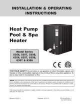
ThermalFlo Heat Pump Dimensions
38.7"
A
4.5"
9.25"
11.25"
32.0"
30.7"
18.0"
6.5"
.5"
PRODUCT SPEC
LABEL
PART N UM BER
SERIAL NO.
CONTAINER ID
ETL LISTED
CONFORMS TO
UL STD 1995
3044065
CERTIFIED TO
CAN/CSA STD C2 2.2 NO. 236
C US
ThermalFlo™ HP
WATER
PRESSURE
THERMOSTAT
HEATING
COOLING
AUTO-HEAT/COOL
REMOTE
POOL
SPA
POWER/
MODE
TEMPERATURE SETTING
POOL SPA
PRESS ANY ARROW ONCE TO
CHECK SET TEMPERATURE
Correct installation is required to assure safe operation. The requirements for Pentair Water heat pumps
include the following:
• Dimensions for critical connections.
• Field assembly (if required).
• Appropriate site location and clearances. (See pages 4-5.)
• Proper electrical wiring. (See pages vi and 11-13.)
• Adequate water flow. (See page vi.)
This manual provides the information needed to meet these requirements. Review all application and installation
procedures completely before continuing the installation.
Location
CAUTION — When pool equipment is located below the pool surface, a leak from any component can cause
large scale water loss or flooding. Pentair Water Pool and Spa, Inc. cannot be responsible for such
water loss or flooding which may cause damage to the product.
Avoid placing the heat pump in locations where it can cause damage by water or condensate
leakage. If this is not possible, provide a suitable drain pan to catch and divert any leakage.
REBMUNLEDOM
0050070090021C0021C/HR0021
"A"noisnemiD”5.33”5.33”5.14”5.14”5.14”5.14
Figure 1.

5
ThermalFlo Installation and User’s Guide
Clearances
All criteria given in the following sections reflect minimum clearances. However, each installation must also be
evaluated, taking into account the prevailing local conditions such as proximity and height of walls, and proximity
to public access areas.
The heat pump must be placed to provide clearances on all sides for maintenance and inspection.
1. At least 24 in. [61cm] access must be available in the front and 12 in. [30 cm] on all the other sides of the
heat pump for service, see Figure 2.
2. If the heat pump is to be installed under a cover or under a vertical overhang, the unit must have a minimum
of four (4) feet [1.22 m] clearance from the top of the heat pump.
3. Install a minimum of five (5) feet [1.52 m] from the inside wall of the pool or spa unless the heat pump is
separated from the pool or spa by a five (5) foot high solid fence or other permanent barrier. Canadian
installations require a minimum of three (3) meters from pool water.
Roof Run-off
Make sure the heat pump is not located where large amounts of water may run-off from a roof into the unit.
Sharp sloping roofs without gutters will allow massive amounts of rain water, mixed with debris from the
roof to be forced through the unit, see Figure 2. A gutter or down spout may be needed to protect the
heat pump.
Equipment Pad
Place the heat pump on a flat slightly pitched surface, such as a concrete or fabricated slab (pad). This allows
proper drainage of condensation and rain water from the base of the unit. If possible, the pad should be placed
at the same level or slightly higher than the filter system equipment pad.
NOTE: Ensure that the pad is pitched not more than 1/4 in. per foot toward the compressor end (front)
of the heat pump. Pitch slab from back to front 1/4 in. per foot maximum and level from side to side.
DO NOT ALLOW ROOF
RUN-OFF TO FLOW INTO
THE UNIT.
25˚
MAXIMIM
ROOF PITCH
WITHOUT A GUTTER
EVAPORATOR
COILS
12"
12"
48"
12"
3"
OPEN
OVER HANG
AIR FLOW OUT
AIR
FLOW
IN
SLAB
SERVICE
ACCESS
24" to 36"
Figure 2.

6
ThermalFlo Installation and User’s Guide
HEAT PUMP
CLAMPS
HEAT PUMP
CLAMPS
Figure 4.
Drainage and Condensation
Condensation will occur from the evaporator coil while the unit is running and drain at a steady rate, usually three
to five gallons per hour, depending upon ambient air temperature and humidity. The more humid the ambient
conditions, the more condensation will be produced. The bottom of the unit acts as a tray to catch rainwater and
condensation. Keep the drain holes, located on the bottom pan of the base of the unit, clear of debris.
Lawn Sprinklers
Make sure there are absolutely no sprinkler heads near the heater that will in
any way spray on or into the heater. Sprinkler damage is not covered under
the warranty agreement.
Make sure that they’re a sufficient distance away so that normal winds will not
carry the mist to the heater. If your filtering system area has plants that need water,
use a trickle type irrigation sprinkler instead of the broadcast type.
The heater is designed to handle the wettest weather conditions that are typical of
rain and humidity, etc. Sprinkler heads force high pressure water into the unit from
the side at an odd angle. Most sprinkler systems are connected to a well system. Most well water is high in
minerals, sulphur and other aggressive contaminates. These contaminates will leave a build up on the evaporator
coils and electronics causing corrosion and hamper the efficiency. If you are located within 15 miles of the
coast, salt may also be in the well water.
Anchor Clamp(s) Installation
In Florida, building codes require that the heat pump be anchored to the equipment pad or platform to
withstand high wind pressures created during hurricanes.
This heat pump is provided with anchor clamps designed to hold the unit to the equipment pad in high wind
conditions. Installation of the anchor clamps are recommended in all installations and are required in Florida
(See Florida Building Code 301.13).
To install the anchor clamps:
1. Be sure that the heat pump is in its permanent location on the equipment pad.
2. Remove the anchor clamps from the installation and instruction package.
Note: Bolts and bolt anchors are not included with the heat pump.
The installer must provide 1/4” x 1-3/8” stainless steel anchor bolts
and the appropriate size concrete anchor to mount the clamp to the
equipment pad.
3. Place the clamps at the base of the heat pump in the locations
indicated in Figure 4, (2 in. undercut [notched area] on either
side).
4. Fit the hook of each clamp over the lip on the base panel of the
heat pump. The hook should fit between the lip of the base panel
and the evaporator coil guard, see Figure 5.
5. Mark the position of the hole in each clamp on the equipment pad.
NO SPRINKLERS
NO SPRINKLERS
NO SPRINKLERS
WITHIN A
6 FT. RANGE
Figure 3.

7
ThermalFlo Installation and User’s Guide
HEAT PUMP
ANCHOR CLAMP
AIR COIL GUARD
AIR
COIL
BOLT ANCHOR
(installer provided)
HEAT PUMP
BASE
1-3/8" HEX BOLT
(installer provided)
CONCRETE
EQUIPMENT PAD
Figure 5.
POOL HEATER
CHEMICAL LOOP
2 LB.
CHEMICAL RESISTANT
CHECK VALVE
CHEMICAL FEEDER
TO POOL OR SPA
POOL PUMP
FROM POOL OR SPA
MANUAL BYPASS VALVE
FILTER
Figure 6. Standard Plumbing Layout
Anchor Clamp(s) Installation, continued
6. Drill a hole in the cement using a masonry drill bit, with a
diameter as determined by the concrete anchor, at each of the
marks on the equipment pad. The hole should be approximately
1½ in. deep.
7. Insert a bolt anchor into each of the holes. Be sure the anchors
are set completely into the holes
8. Position the anchor clamps so that the holes in the clamps are
over the bolt anchors. Be sure that the clamp hooks are over the
lip of the heat pump base, see Figure 5.
9. Insert an anchor bolt through each clamp into the anchor and
tighten to secure the clamp and heat pump to the equipment pad.
Water Connections
Plumbing layout
See Figure 6, illustrating the standard plumbing layout with a single heat pump unit. Following the diagram from
right to left, the plumbing sequence is as follows:
Pool > Skimmer and Main Drain > Pool Pump > Filter > Heat Pump > Check Valve > Chemical Loop > Chlorinator > Pool
NOTE: For normal installations, do not install a shut-off valve or any kind of variable restriction in
the water piping between the heat pump outlet and the pool/spa.
The heat pump must be protected from back-siphoning of water. If there is any chance of back-siphoning,
provide a check valve between the pool and the heat pump outlet. Arrangement of pool system components
other than as illustrated in Figure 6. and the following diagrams can affect the operation of the heat pump’s
water pressure switch. Location of the heat pump above or below the pool water surface can also affect
operation of the switch. In general, the pressure switch can be adjusted to accommodate this effect if the heat
pump water connections are no more than six (6) feet below the pool water surface or no more than fifteen 15
feet above it. See instructions for pressure switch adjustment (page 20) in the heat pump start-up section of this
manual for more information. If the heat pump is installed outside of this range, an external pressure switch may
need to be installed in the plumbing upstream of the heat pump. Call the Pentair Water Heat Pump Technical
Service department at (800) 831-7133 for details.
Be advised that when pool equipment is located below the pool surface a leak can result in large-scale water
loss or flooding. Pentair cannot be responsible for such water loss or flooding or the damage caused by either
occurrence.

8
ThermalFlo Installation and User’s Guide
Water Connections at the Heat Pump
Two inch Quick Connect fittings have been installed on the water inlet
and outlet connections, see Figure 7. Filtered cool water is plumbed
to the inlet, located on the right side of the heat pump front panel.
Heated water flows through the outlet, located on the left side of the
heat pump front.
Plastic piping (PVC Schedule 40) should be connected to the heat
pump. The unions, provided with the unit, accept 2 in. PVC pipe.
CAUTION — Make sure that flow requirements and pool water
turnover rates can be maintained with the installation of
additional heat pumps and plumbing restrictions.
Check Valve Installation
The heat pump must be protected from back-siphoning of water. If there is any chance of back-siphoning,
provide a check valve between the pool and the heat pump outlet.
CAUTION — The chlorinator placement, water balance, and where chemicals are added, are very important
aspects of the installation. Failure to protect the heat pump unit from chemical damage is not
covered under the warranty.
When an automatic chemical feeder is installed in the plumbing, it must be installed downstream of the
heat pump. A check valve must be installed between the heat pump and the chemical feeder to prevent
back-siphoning of chemically saturated water into the heat pump where it will damage the components.
Automatic Flow Control Valve
The inlet/outlet header of the ThermalFlo HP heat pump comes equipped with an internal automatic flow
control valve. The automatic flow control valve maintains the proper flow through the heat pump at rates up to
125 gpm (475 lpm). If the filter system flow rate is higher than 125 gpm (475 lpm), install a manual bypass
valve, see Figure 6 on page 7.
NOTE: Be advised that if your circulation pump is over 2 HP or if the total flow exceeds 125 gpm, you
will have to add an external bypass valve. Excess water flow will damage the heat exchanger.
Water
Inlet Union
Water
Outlet Union
Figure 7.

9
ThermalFlo Installation and User’s Guide
Multiple Unit Installation
Heat Pump, Heater and/or Solar Combination
In certain regions of the country it may be more economical to run a heat pump during the warmer months and
a gas heater during the cooler months. In some situations it may be desirable to run the heat pump in the
“Chiller” mode, if so equipped, during the hottest portion of the year and a heater during the cooler months.
The Pentair Water heat pump may be used in conjunction with a gas or electric heater or any combination of
heat sources including solar. All heat sources must be plumbed in series to work correctly and efficiently.
A recommended plumbing layout for a heat pump / heater / solar combination heating system for a pool / spa
combination is shown in Figure 8. Your system may not contain all of these components, but the basic plumbing
will apply by eliminating the component in the illustration that is not a part of your system.
HEATER
HEAT P
U
M
P
T
O
SO
LA
R
FILTER
S
DRAIN
P
OOL
DRA
S
P
A
INTAKE
P
OOL
INTAKE
S
P
A
RETURN
P
OOL
RET
U
R
N
S
P
A
M
AKE-
UP
VALVE
VALVE
Figure 8.

10
ThermalFlo Installation and User’s Guide
Multiple Heat Pump Connections
All plumbing on multiple heat pump installations must be done in parallel see Figures 9 and 10. An equal flow
of water to each heat pump is important for optimum operation.
NOTE: It may be necessary to adjust water pressure switch if a unit is installed below the water
level. See page 20 for details on when and how to adjust the pressure switch.
Each heat pump allows a maximum flow rate of 125 gpm and requires a minimum of 30 gpm.
24 inches min. clearance around evap.
Extend12" past
end heater inlet
for hydraulic
balancing
Extend12" past
end heater inlet
for hydraulic
balancing
Pool Pump
Flow Meter
Minimum
2" PVC Pipe
2" PVC Pipe
Flow Meter
To Pool
OPTIONAL
2" Check Valve Bypass
Check Valves are
optional on heater inlets
but will help system
balancing
24"
Figure 9. Two Heat Pump Plumbing Layout
24 inches min. clearance around evap.
Extend12" past
end heater inlet
for hydraulic
balancing
Extend12" past
end heater inlet
for hydraulic
balancing
Pool Pump
Flow Meter
Minimum
3" PVC Pipe
2" PVC Pipe
Flow Meter
To Pool
3" Ball Valve Bypass
Check Valves are
optional on heater inlets
but will help for system
balancing
24"
2" PVC
Pipe
2" PVC
Pipe
2" PVC
Pipe
3" PVC Pipe3" PVC Pipe
Figure 10. Four Heat Pump Plumbing Layout

11
ThermalFlo Installation and User’s Guide
Electrical Connections
WARNING —Risk of electrical shock or electrocution.
This heat pump contains wiring that carries high voltage. Contact with these wires could result in death
or serious injury to pool or spa users, installers, or others due to electrical shock, and may also cause
damage to property. Always disconnect power circuit before connecting the heat pump.
CAUTION — Label all wires prior to disconnection when servicing controls. Wiring errors can cause improper and
dangerous operation. Verify proper operation after servicing.
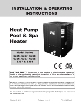
General Information
Wiring connections must be made exactly as shown in the wiring diagram found on the inside of the heat pump
access panel, see Figure 11 on page 12. The heat pump must include a definite means of grounding and
bonding. There is a ground lug inside the heat pump electrical compartment and a bonding lug on the left side
of the heat pump.
Main Power
Electrical wiring to the heat pump must be in accordance with the latest edition of the National Electric Code
(NEC), ANSI/National Fire Protection Association (NFPA) 70 in the United States, and in Canada, the
Canadian Electrical Code (CEC) C22.1, unless local code requirements indicate otherwise. All wiring must be
done by a certified electrician.
The following is the procedure to wire the ThermalFlo HP to the electrical source:
Be sure the power to the circuit for the heat pump is turned off.
1. Remove the front left panel of the heat pump cabinet, (you do not need to remove the torque head
screw at the top left corner).
2. Remove the service panel to the heat pump electrical compartment. (front left corner of unit)
3. Electrical supply lines must be run through watertight conduit. Run the wires and conduit from the power
source and connect them to the conduit connection on the left side of the heat pump.
4. Connect the power leads to the terminals on the main contactor as shown in the wiring diagram.
5. Verify that all other contactor wires are secure, they may have loosened during shipment.
6. Connect the ground wire to the ground lug provided on the bottom of the electrical compartment.
7. Replace the service panel and reinstall screws to hold it in place.
8. Replace the front left panel.
9. Connect a copper bonding wire (8 AWG) to the bonding lug on the left side of the heat pump.
Bonding
CAUTION — This heater must be connected to a bonding grid with a solid copper wire not smaller in diameter
than 8 ga.
The National Electrical Code and most other codes require that all metallic components of a pool structure,
including reinforcing steel, metal fittings, and above ground equipment be bonded together with a solid copper
conductor not smaller than 8 AWG. The heat pump, along with pumps and other pool equipment must be
connected to this bonding grid. A bonding lug is provided on the left side of the heat pump to ensure this
requirement is met.

12
ThermalFlo Installation and User’s Guide
Wiring Diagram
473073
Contactor
Compressor
Incoming 220 VAC
Power Connection
R
C
S
REMOTE
10K
Thermistor
1
2
3
4
5
6
Capacitor
NC
NO
Fan
Relay
COM
Fan
Green
Water Pres Sw
Lo Ref Pres SwHi Ref Pres Sw
460812, 460813, 460814, 460815, 460822, 460804
TBL
TBR
Optional
Reversing Valve on
460822
Switch factory set to H
for 460812, 460813,
460814, 460815, set to
C for 460804, and set to
AU for 460822
(on back of circuit board)
Transformer
24
VAC
208 VAC
COM
240 VAC
1
2
3
4
5
6
7
8
WHITE
WHITE
WHITE
WHITE
BLUE
YELLOW
BLUE
YELLOW
WHITE
WHITE
BLACK
RED
BLACK
RED
RED
RED
BLACK
BLACK
PURPLE
RED
BLACK
BLACK
RED
PURPLE
50 mf 7.5 mf
PURPLE
BLACK
BLACK
WHITE
PURPLE
BLUE
BLUE
YELLOW
PURPLE
ORANGE
BLACK
BROWN
PINK
BROWN
TAN
BROWN
BLACK
Red
RED
BROWN
BLACK
GREEN
Heat Pump Control Board
TEMPERATURE
24 VAC
HCAU
THERMISTER
WATER
FLOW
FA
SPA
COM
POOL
N
S
OLENOID
COMPRESSOR
HI
PRES
LOW
PRES
Figure 11.
/