Page is loading ...

15-Year Limited Warranty
1. Please read and save this manual.
2. To reduce the risk of electric shock, insure electricity has been
turned off at the circuit breaker or fuse box before beginning.
3. All wiring must be in accordance with the National Electrical
Code and local electrical codes. Electrical installation should be
performed by a qualified licensed electrician.
4. WARNING: To reduce the risk of electrical shock and fire, do
not use this fan with any solid-state fan speed control device.
5. The outlet box and support structure must be securely mounted
and capable of reliably supporting a minimum of 50 pounds. Use
only UL Listed outlet boxes marked "FOR FAN SUPPORT."
WARNING
TO REDUCE THE RISK OF FIRE, ELECTRIC SHOCK OR PERSONAL
INJURY, MOUNT TO OUTLET BOX MARKED ACCEPTABLE POR
FAN SUPPORT ONLY AND USE MOUNTING SCREWS PROVIDED
WITH THE OUTLET BOX. MOST OUTLET BOXES COMMONLY USED
FOR THE SUPPORT OF LIGHTING FIXTURES ARE NOT ACCEPTABLE
FOR FAN SUPPORT AND MAY NEED TO BE REPLACED. CONSULT A
QUALIFIED ELECTRICIAN IF IN DOUBT.
The fan must be mounted with a minimum of 7 feet clearance
from the trailing edge of the blades to the floor.
-IMPORTANT.
BEFORE SERVICING OR CLEANING UNIT, SWITCH POWER OFF AT
SERVICE PANEL AND LOCK SERVICE DISCONNECTING MEANS TO
PREVENT POWER FROM BEING SWITCHED ON ACCIDENTALLY. WHEN
THE SERVICE DISCONNECTING MEANS CANNOT BE LOCKED,
SECURELY FASTEN A PROMINENT WARNING DEVICE, SUCH AS A
TAG, TO THE SERVICE PANEL.
7. Do not operate reversing switch while fan blades are in motion.
Fan must be turned off and blades stopped before reversing
blade direction.
8. Avoid placing objects in the path of the blades.
9. To avoid personal injury or damage to the fan and other items,
be cautious when working around or cleaning the fan.
10. Do not use water or detergents when cleaning the fan or fan
blades. A dry dust cloth or lightly dampened cloth will be
suitable for most cleaning.
11. After making electrical connections, spliced conductors should
be turned upward and pushed carefully up into outlet box. The
wires should be spread apart with the grounded conductor and
the equipment-grounding conductor on one side of the outlet
box.
12. Electrical diagrams are for reference only. Light kits that are not
packed with the fan must be UL Listed and marked suitable for
use with the model fan you are installing. Switches must be UL
General Use Switches. Refer to the instructions packaged with
the light kits and switches for proper assembly.
WARNING
TO REDUCE THE RISK OF PERSONAL INJURY, DO NOT BEND
THE BLADE BRACKETS (ALSO REFERRED TO AS "FLANGES")
DURING ASSEMBLY OR AFTER INSTALLATION. DO NOT
INSERT OBJECTS IN THE PATH OF THE BLADES.
Safety Rules 1.
Date Purchased .
Store Purchased.
Model No. __
Serial No. ___
The retailer warrants the fan motor to be free from defects in workmanship and material
present at time of shipment from the factory for a period of fifteen years after the date of
purchase by the original purchaser. The retailer also warrants that all other fan parts,
excluding any glass or plexiglass blades, to be free from defects in workmanship and
material at the time of shipment from the factory for a period of one year after the date of
purchase by the original purchaser. We agree to correct such defects without charge or at
our option replace with a comparable or superior model if the product is returned to the
retailer. To obtain warranty service, you must present a copy of the receipt as proof of
purchase. All costs of removing and reinstalling the product are your responsibility.
Damage to any part such as by accident or misuse or improper installation or by affixing any
accessories, is not covered by this warranty. Because of varying climatic conditions in the
United States this warranty does not cover any changes in brass finish, including rusting,
pitting, corroding, tarnishing or peeling. Brass finishes of this type give their longest
useful life when protected from varying weather conditions. A certain amount of "wobble"
is normal and should not be considered a defect. Servicing performed by unauthorized
persons shall render the warranty invalid. There is no other express warranty. The
retailer hereby disclaims any and all warranties, including but not limited to, those of
merchantability and fitness for a particular purpose to the extent permitted by law. The
duration of any implied warranty which cannot be disclaimed is limited to the time period
as specified in the express warranty. Some states do not allow limitation on how long an
implied warranty lasts, so the above limitation may not apply to you. The retailer shall
not be liable for incidental, consequential, or special damages arising out of or in
connection with product use or performance except as may otherwise be accorded
by law. Some states do not allow the exclusion of incidental'or consequential damages,
so the above exclusion or limitation may not apply to you. This warranty gives specific
legal rights, and you may also have other rights which vary from state to state. This
warranty supersedes all prior warranties.
Vendor No.
654033
SKU. 525-963 IJPC. 043263 129170
SKU. 525-930 UPC. 043263 129187
SKU. 525
-
918 UPC. 043263 129194

Unpack your fan and check the contents. You should have the following items:
1. Canopy with "Slide-on" Ceiling
Mounting Bracket
2. 4'/2" Downrod Assembly
3. Fan Motor with Switch Housing
4. Light Kit
WARNING
5. Set of Blade Holders (5) (with blade
holder screws pre-installed)
6. Set of Blades (5)
7. Lamp Shade (3)
8. 60 Watt Medium Base Bulb (3)
.NOTE-
9. Loose Parts Bags Containing:
a. Machine Screws (16) b.
Wire Nuts (3) c. Pivot Pin (1)
d. Split Pin (1) e. Pull Chain
Pendant (2) f. Fan Blade
Balancing Kit
DO NOT INSTALL OR USE FAN
IF ANY PART IS DAMAGED OR MISSING.
CALL TOLL FREE 1-800-527-3675
THIS FAN INCLUDES LIGHT KIT.
FOR USE WITHOUT LIGHT KIT, A SWITCH
HOUSING COVER IS AVAILABLE BY
CALLING
1-800-527-3675.
2. Unpacking Your Fan
Tools Required
Phillips screwdriver, straight slot screwdriver,
adjustable wrench, step ladder, and wire
cutters.
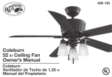
Mounting Options
If there isn't an existing UL Listed metal
mounting box, then read the following
instructions. Disconnect the power by
removing fuses or turning off circuit
breakers.
Secure the outlet box directly to the building
structure. Use appropriate fasteners and
building materials. The outlet box and its
support must be able to fully support the
moving weight of the fan (at least 50 Ibs.). Do
not use plastic outlet boxes.
Figures 1. 2, and 3 are examples of different
ways to mount the outlet box.
NOTE: You may need a longer downrod to
maintain proper blade clearance when
installing on a steep, sloped ceiling. The
maximum angle allowable is 30°. If the
canopy touches downrod, remove the
decorative canopy bottom cover and turn
the canopy 180° before attaching the canopy
to the mounting bracket.
-Hr
Outlet Box
Figure 4
To hang your fan where there is an existing
fixture but no ceiling joist, you may need an
installation hanger bar as shown in Figure 4
(available at your Hampton Bay Retailer).
9. Loose Parts
a
2.
c
Outlet Box
Figure 1
Figure 2
„ Provide Strong Support
Recessed
Outlet Box
Figure 3
7/7*
T/l
l

Hanging the Fan
REMEMBER to turn off the power. Follow
the steps below to hafig your fan properly.
NOTE: The ceiling fan is supplied with two
types of hanging assemblies; the standard
ceiling installation using the downrod with ball
and socket, and the "close-to-ceiling"
installation. The "close-to-ceiling" installation is
recommended in rooms with less than 8-foot
ceilings or in areas where additional space is
desired from the floor to the fan blades. When
using the standard downrod installation, the
distance from the ceiling to the bottom of the
fan blades will be approximately 12 inches for
the 4'/2-inch downrod. The "close-to-ceiling"
installation reduces this distance to 8'/2 inches.
Once you have decided which ceiling
installation you will use, proceed with the
following instructions. Where necessary, each
section of the instructions will note the
different procedures to follow for the two
types of installation.
STANDARD CEILING INSTALLATION
1. Remove the mounting bracket from the
canopy by loosening the four screws on the
top of the canopy. Remove the two non-
slotted screws and loosen the slotted
screws. This will enable you to remove the
mounting bracket.
2. Place the downrod assembly through the
ceiling canopy and insert the motor wires
through the downrod assembly (Figure 5).
Ceiling
Canopy
Figure 5
3. Push the pivot pin through the hanger and
downrod holes (Figure 6). Secure the pivot
pin by inserting the split pin and bending
the ends to prevent it from falling out of
the holes (Figure 6).
4. Secure the hanger and downrod by
tightening the two screws on the hanger
(Figure 6).
Pivot Pin
Hanger
Figure 6
Canopy
Bottom
Cover
Figure 7
CLOSE-TO-CEILING INSTALLATION
1. Remove the mounting bracket from the
canopy by loosening the four screws on the
top of the canopy. Remove the two non-
slotted screws and loosen the slotted
screws. This will enable you to remove the
mounting bracket.
2. Remove the decorative canopy bottom
cover from the canopy by depressing the
three studs (Figure 7).
3. Remove the three screws and spring
washers from the hanger.
4. Mount the ceiling canopy to the hanger by
tightening back the three screws and spring
washers (Figure 8).
. WARNING
FAILURE TO COMPLETELY TIGHTEN THE
THREE SCREWS AND SPRING WASHERS IN
STEP 3 COULD RESULT IN FAN LOOSENING
AND POSSIBLY FALLING.
Installing Fan to the
Electrical Box
1. Pass the 120-volt supply wires through the
center hole in the mounting bracket as
shown in Figure 9.
2. Attach the mounting bracket on the
electrical box by sliding the mounting
bracket over the screws provided with the
outlet box. When using close-to-ceiling
mounting, it is important that the mounting
bracket be level. If necessary, use leveling
washers (not included) between the
mounting bracket and the electrical box.
Note that the flat side of the mounting
bracket is to be toward the electrical box
(Figure 9).
-WARNING
WHEN MOUNTING ON A SLOPED CEILING, THE
STANDARD BALL/DOWNROD MOUNTING
METHOD MUST BE USED. MAKE SURE THE
MOUNTING BRACKET SLOTS ARE ON THE
LOWER SIDE BY SLIDING THE MOUNTING
BRACKET FROM THE TOP DOWN.
3. Securely tighten the two mounting screws.
4. Carefully lift the fan assembly up to the
mounting bracket. If using close-to-ceiling
mounting, hang the fan on the hook
provided by utilizing one of the holes at
the outer rim of the ceiling canopy. If
using standard mounting, seat the hanger
ball in the mounting bracket socket. Make
sure the tab on the mounting bracket
socket is properly seated in the groove in
the hanger ball. (Figure 10).
Motor Wires
Downrod
Screws
1 I
4.
Mounting
Screws
(supplied with
Electrical Box)
Slide Mounting
Bracket Over
^Screws Heads
Ceiling
Mounting
Bracket
UL LISTED
Electrical
Box
Hook
Hanger
Close-to Ceiling
Mounting
Standard Mounting
Screw and
Lockwasher
Ceiling
Canopy
Figure 8
Figures 120V Wires
Figure 10

WARNING .
THE HOOKAS
stvam W
FIG
.
w»s
ONLY TO
BALANCE FAN WHILE ATTACHING THE WIRING.
FAILURE TO «ANC,AfeSW»«« IN FIG, 10 MAY
RESULT JN HOOK BREAKING CAUSING THE FAN
TO FALL. HOOK MUST PASS FROM INSIDE TO
OUTSIDE-QF CANOPY.
Making the Electrical
Connections
If you feel that you do not have enough
electrical wiring knowledge or experience,
have your fan installed by a licensed
electrician.
WARNING-
TO AVOID POSSIBLE ELECTRICAL SHOCK, BE
SURE ELECTRICITY IS TURNED OFF AT THE
MAIN FUSE BOX BEFORE WIRING.
NOTE: IF YOU ARE NOT SURE THE
ELECTRICAL BOX AND FAN ARE GROUNDED,
CONTACT A LICENSED ELECTRICIAN FOR
ADVICE. THEY MUST BE GROUNDED FOR
SAFE OPERATION.
WARNING.
EACH WIRE NUT (WIRE CONNECTOR)
SUPPLIED WITH THIS FAN IS DESIGNED TO
ACCEPT UP TO ONE 12 GAUGE HOUSE WIRE
AND TWO W«ES FROM THE FAN. IF YOU
HAVE LARGER THAN 12 GAUGE HOUSE
WIRING OR MORETOAN ONE HOUSE WIRE
TO CONNECT f«J THE FAN WIRING,
CONSULT AN ELECTRICIAN FOR THE
PROPER SIZE WIRE NUTS TO USE.
1. Connect the ground conductor of the 120V
supply (this may be a bare wire or a wire
with green colored insulation) to the green
ground lead(s) of the fan (Figure 11).
When using standard ceiling installation,
there are two green ground leads, one from
the ceiling mounting bracket and one from
the downrod.
When using close-to-ceiling installation,
there is only one green ground lead from
the ceiling mounting bracket since the
downrod is not used.
2. Connect the fan motor white wire to the
supply white (neutral) wire using a wire nut
(Figure 11). Connect the fan motor black
wire and the light kit blue wire to the
supply black (hot) wire using a wire nut
(Figure 11). Do not connect the blue wire
if light kit is not used. Your fan is now
wired to be turned on and off from the pull
chain switch. Turn the wire nut
connections upward, spreading them apart
so that the green (ground) and white wires
will be on one side of the outlet box and
the black and blue wires will be on the
other side, and push them up into the
outlet box.
WARNING
CHECK TO SEE THAT ALL CONNECTIONS
ARE TIGHT, INCLUDING GROUND, AND THAT
NO BARE WIRE IS VISIBLE AT THE WIRE
NUTS, EXCEPT FOR THE GROUND WIRE.
If you wish to control the light from a wall
switch and the fan from the pull chain switch
or if you wish to control both fan and light
from wall switches, refer to wiring diagrams
in Figure 12 and 13.
Figure 11
Diagram indicates light kit wiring
Figure 12
Diagram indicates optional wiring
Figure 13
Diagram indicates optional wiring
Figures 12 and 13 illustrate the wiring connections for optional wall control (available at your Hampton Bay Retailer).
6.
SUPPLY CIRCUIT
i .!.
SUPPLY CIRCUIT
SUPPLY CIRCUIT
I .!.
Ground
Conductor
Outlet Box
Green
Ground
Lead
Ground to
Down rod
Ground
Conductor
— Outlet Box
„ _ Green T —
— Ground Lead
Ground to
Downrod
Ground
Conductor
— Outlet Box
Green
Ground
Lead
Ground to
Downrod
WHI
TE
BLUE
(
BLA
CK
'
7.

Finishing the Fan
Installation
STANDARD CEILING MOUNTING
———————- WAftNlNG———————
WHEN USING THE STANDARD BALUDOWNROD
MOUNTING, THE TAB IN THE RING AT THE
BOTTOM OF THE MOUNTING BRACKET MUST
REST IN THE GROOVE OF THE HANGER BALL.
FAILURE TO PROPERLf SEAT THE TAB IN THE
GROOVE COULD CAUSE DAMAGE TO WIRING.
1. Align the locking slots of the ceiling
canopy with the two screws in the
mounting bracket. Push up to engage the
slots and turn clockwise to lock in place.
Immediately tighten the two mounting
screws firmly.
2. Install the remaining two mounting screws
into the holes in the canopy and tighten
firmly.
3. You may now proceed to attaching the fan
blades.
CLOSE- TO-CEILING MOUNTING
1. Carefully unhook the fan from the
mounting bracket and align the locking
slots of the ceiling canopy with the two
screws in the mounting bracket. Push up to
engage the slots and turn clockwise to lock
in place. Immediately tighten the two
mounting screws firmly.
-WARNING-
LOCKING SLOTS OF CEILING CANOPY ARE
PROVIDED ONLY AS AN AID TO MOUNTING.
DO NOT LEAVE FAN ASSEMBLY
UNATTENDED UNTIL ALL FOUR CANOPY
SCREWS ARE ENGAGED AND FIRMLY
TIGHTENED.
2. Install the remaining two mounting screws
into the holes in the canopy and tighten
firmly.
3. You may now proceed to attaching the fan
blades.
• CAUTION •
DO NOT OPERATE FAN UNTIL BLADES ARE IN
PLACE. NOISE AND FAN DAMAGE COULD
RESULT.
Attaching the Fan Blades
Note: Your fan blades are reversible. Select
the blade side finish which best accentuates
your decor.
1. Mount the blade holders to the fan blades
using the screws provided - 3 per blade
(Figure 14). Please note the rubber washers
are pre-attached to the blade holder.
2. The fan blade assemblies are to be attached
to the motor using the blade holder screws
that are pre-installed into the blade holder.
The procedure to attach blade assemblies is
as follows:
c.
FAILURE TO FOLLOW ABOVE
PROCEDURE COULD RESULT INFAN
WOBBLE.
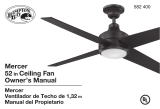
Blade Balancing
All blades are grouped by weight. Because
natural woods vary in density, the fan may
wobble even though the blades are weight
matched.
The following procedure should correct most
fan wobble. Check after each step.
1. Check that all blade and blade holder
screws are secure.
2. Most fan wobble problems are caused
when blade levels are unequal. Check this
level by selecting a point on the ceiling
above the tip of one of the blades. Measure
this distance as shown in Figure 16. Rotate
the fan until the next blade is positioned for
measurement. Repeat for each blade.
Measurements should be within 1/8".
8.
a. Position the blade holder wider the
motor
'isiic1i
:
Mj:;ftegiwnt;
:
:p6st
OR
.;'Stet: in the
'
3. If blade wobble is still noticeable,
interchanging two adjacent (side by side)
blades can redistribute the weight:,and
possibly result in smoother operation.
b. Tighten ;ifc -pre-installeS blade
holder
¥
semblies as
Touch
Ceiling
Figure 16
Pre
-
installed
Blade
Holder Screw
Q


/