
C242
SHINDAIWA OWNER’S/OPERATOR’S MANUAL
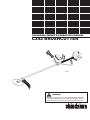
C242 BRUSHCUTTER
WARNING!
Minimize the risk of injury to yourself and others! Read this
manual and familiarize yourself with the contents. Always
wear eye and hearing protection when operating this unit.
Part Number 81644 Rev 1/07

2
Throughout this manual are special
“attention statements”.
IMPORTANT!
The operational procedures described
in this manual are intended to help you
get the most from this unit as well as
to protect you and others from harm.
These procedures are guidelines for safe
operation under most conditions, and are
not intended to replace any safety rules
and/or laws that may be in force in your
area. If you have questions regarding your
242 series hand held power equipment,
or if you do not understand something in
this manual, your Shindaiwa dealer will be
glad to assist you. You may also contact
Shindaiwa Inc. at the address printed on
the back of this Manual.
Attention StatementsIntroduction
PAGE
The Shindaiwa 242 Series hand held
power equipment has been designed and
built to deliver superior performance and
reliability without compromise to quality,
comfort, safety or durability.
Shindaiwa engines represent the leading
edge of high-performance engine technol-
ogy, delivering exceptionally high power
with remarkably low displacement and
weight. As an owner/operator, you’ll soon
discover for yourself why Shindaiwa is
simply in a class by itself!
Shindaiwa Inc. reserves the right to
make changes to products without prior
notice, and without obligation to make al-
terations to units previously manufactured.
Attention Statements. ................................2
Safety Instructions .....................................2
Safety Labels ...............................................4
Product Description ...................................5
Specifications ..............................................5
Assembly .....................................................6
Adjustments................................................7
Installing a Trimmer Head........................8
Installing a Blade........................................9
Mixing Fuel.............................................. .10
Starting the Engine.. ................................10
Stopping the Engine ................................11
Adjusting Engine Idle ..............................11
Checking Unit Condition.........................12
Shoulder Strap ..........................................12
Cutting Grass with a Trimmer Head ......12
Using a Blade............................................13
Maintenance .............................................14
Long Term Storage................................... 17
Blade Sharpening......................................17
Troubleshooting Guide ...........................18
Emission System Warranty .....................20
Contents
IMPORTANT!
The information contained in this
owner’s/operator’s manual describes units
available at the time of publication.
CAUTION!
A statement preceded by the word
“CAUTION” contains information that
should be acted upon to prevent
mechanical damage.
WARNING!
A statement preceded by the triangular
attention symbol and the word
“WARNING” contains information that
should be acted upon to prevent
serious bodily injury.
Work Safely
Shindaiwa trimmers operate at very high
speeds and can do serious damage or
injury if they are misused or abused.
Never allow a person without training or
instruction to operate this unit!
Stay Alert
You must be physically and mentally fit to
operate this unit safely.
Safety Instructions
WARNING!
WARNING!
Never operate power equipment of any
kind if you are tired or if you are under
the inuence of alcohol, drugs,
medication or any other substance that
could affect your ability or judgement.
Never make unauthorized
attachment installations. Do not
use attachments not approved by
Shindaiwa for use on this unit.
WARNING!
The engine exhaust from this product
contains chemicals known to the State
of California to cause cancer, birth
defects or other reproductive harm.
NOTE:
A statement preceded by the word “NOTE”
contains information that is handy to know
and may make your job easier.
IMPORTANT!
A statement preceded by the word
“IMPORTANT” is one that possesses
special signicance.
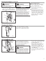
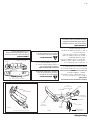
Read and follow this
operators manual.
Failure to do so could
result in serious injury.
Wear eye and hearing
protection at all times
during the operation
of this unit.
Keep bystanders
at least 50 feet (15 m)
away during operation.
Beware of thrown or
ricocheted objects.
Do not operate this unit with a
blade unless the unit is equipped
with a Shindaiwa-approved
handlebar or barrier.
Always wear a harness when
operating this unit with a blade.
A harness is also recommended
when using trimmer line.
If unit is used as a brushcutter,
beware of blade thrust. A jammed
blade can cause the unit to jerk
suddenly and may cause the
operator to lose control of the unit.
WARNING!
Minimize the Risk of Fire
NEVER smoke or light res near
the engine.
ALWAYS stop the engine and allow it
to cool before refueling. Avoid overll-
ing and wipe off any fuel that may have
spilled.
ALWAYS inspect the unit for fuel
leaks before each use. During each
rell, check that no fuel leaks from
around the fuel cap and/or fuel tank.
If fuel leaks are evident, stop using the
unit immediately. Fuel leaks must be
repaired before using the unit.
ALWAYS move the unit to a place well
away from a fuel storage area or other
readily ammable materials before
starting the engine.
NEVER place ammable material
close to the engine mufer.
NEVER operate the engine without
the spark arrester screen in place.

3
WARNING!
Use Good Judgment
ALWAYS wear eye protection to shield
against thrown objects.
NEVER run the engine when
transporting the unit.
NEVER run the engine indoors! Make
sure there is always good ventilation.
Fumes from engine exhaust can cause
serious injury or death.
ALWAYS clear your work area of trash
or hidden debris that could be thrown
back at you or toward a bystander.
ALWAYS use the proper cutting tool for
the job.
ALWAYS stop the engine immediately
if it suddenly begins to vibrate or shake.
Inspect for broken, missing or improp-
erly installed parts or attachments.
NEVER extend trimming line beyond
the length specied for your unit.
ALWAYS keep the unit as clean as
practical. Keep it free of loose
vegetation, mud, etc.
ALWAYS hold the unit rmly with both
hands when cutting or trimming, and
maintain control at all times.
ALWAYS keep the handles clean.
ALWAYS disconnect the spark plug
wire before performing any
maintenance work.
ALWAYS, if a saw blade should bind
fast in a cut, shut off the engine
immediately. Push the branch or tree to
ease the bind and free the blade.
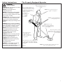
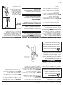
Safety Instructions The Properly Equipped Operator
Always operate with both hands
firmly gripping the unit.
Wear close-fitting clothing to pro-
tect legs and arms. Gloves offer
added protection and are strongly
recommended. Do not wear
clothing or jewelry that could get
caught in machinery
or underbrush.
Secure hair so it is
above shoulder
level. NEVER
wear shorts!
Wear hearing protection devices
and a broad-brimmed hat or
helmet.
Always wear eye protection such as
goggles or safety glasses.
Keep away from the rotating
trimmer line or blade at all times,
and never lift a moving attachment
above waist-high.
Wear appropriate footwear (non-skid boots
or shoes): do not wear open-toed shoes or
sandals. Never operate the unit while
barefoot!
Keep a proper footing
and do not over-
reach—maintain your
balance at all times dur-
ing operation.
Always make sure the
appropriate cutting attachment
shield is correctly installed and in
good condition.
Figure 1
Always wear a shoulder strap or a harness when oper-
ating a unit equipped with a blade.

4
Safety Labels
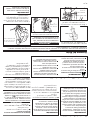
Figure 3
Be Aware of the Working Environment
Avoid long-term
operation in very hot or
very cold weather.
Make sure bystanders or observers outside the
50-foot “danger zone” wear eye protection.
Be extremely careful
of slippery terrain,
especially during
rainy weather.
Always make sure the
appropriate cutting attachment
shield is correctly installed.
If contact is made with a hard
object, stop the engine and
inspect the cutting attachment
for damage.
When operating in rocky terrain or near
electric wires or fences, use extreme cau-
tion to avoid contacting such items with
the cutting attachment.
Be constantly alert for objects and debris that
could be thrown either from the rotating cutting
attachment or bounced from a hard surface.
Reduce the risk of
bystanders being struck
by flying debris. Make
sure no one is within 50
feet (15 meters)—that’s
about 16 paces—of an
operating attachment.
Figure 2
50
FEET
C242
Safety and Operation Information
Labels: Make sure all informa-
tion labels are undamaged and
readable. Immediately replace
damaged or missing information
labels. New labels are avail-
able from your local authorized
Shindaiwa dealer.
IMPORTANT!
This label indicates the minimum
distance between front handle and
rear grip per ANSI B175.3.

5
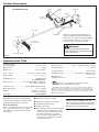
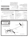
Brushcutter Blade
Cutting
Attachment Shield
Gear Case
Throttle
Trigger
Product Description
Using the accompanying illustrations as
a guide, familiarize yourself with this unit
and its various components. Understanding
your unit helps ensure top performance,
long service life, and safer operation.
Figure 4
Specications C242
C242 dry weight
(less attachments) ...................................................12.4 lb./5.6 kg
Engine model.........................................................................S242E
Engine type.............................................................2 cycle catalyst
Bore x stroke...................................1.3 x 1.1 in./33 mm x 28 mm
Displacement .....................................................1.5 cu. in./23.9 cc
Maximum power ....................................................1.0 HP/0.8 kW
@ 8,000 RPM (min
-1
)
Fuel/oil ratio ...........................50:1 with ISO-L-EGD or JASO FC
class 2-cycle mixing oil*
Carburetor type ............................Walbro WYK, diaphragm-type
Fuel tank capacity .................................................22.3 oz./670 ml
Ignition .........................................................One-piece electronic,
transistor-controlled
Spark plug...............................................................NGK BPMR6A
Prior to Assembly
Before assembling, make sure you have all
the components required for a complete
unit and inspect unit and components for
any damage.
Specifications are subject to change without notice.
Air cleaner type ........................Non-reversible foam filter element
Starting method .......................................................................Recoil
Stopping method ............................................................Slide switch
Transmission type .............................Automatic, centrifugal clutch
w/bevel gear
EPA Emission
Compliance Period**.......................................................Category A
** The EPA emission compliance referred to on the emission compliance
label located on the engine, indicates the number of operating hours for
which the engine has been shown to meet Federal emission requirements.
Category C = 50 hours (Moderate), B = 125 hours (Intermediate) and A =
300 hours (Extended).
n Engine/Outer tube assembly
n Handlebar and Throttle assembly
n Cutting attachment shield
n Cutting attachment
n Kit containing cutting attachment shield
mounting bracket and hardware, this
owner’s/operator’s manual and tool kit
for routine maintenance. Tool kits
vary by model and may include a hex
wrench, and a spark plug/screwdriver
combination wrench.
This unit comes fully assembled with the
exception of the handlebar, cutting attach-
ment shield and cutting attachment.
* meets or exceeds these specifications and is
recommended for all Shindaiwa products.
WARNING!
Do not make unauthorized modica-
tions or alterations to any of these units
or their components.
C242 BRUSHCUTTER
Outer Tube
Handle Bar
Ignition
Switch
Fuel
Tank
IMPORTANT!
The terms “left”, “left-hand”, and “LH”;
“right”, “right-hand”, and “RH”; “front” and
“rear” refer to directions as viewed by the
operator during normal operation.
Muffler
Spark Plug
Hanger
Throttle
Interlock
Strap

6
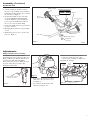
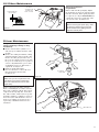
Figure 5
Cutting Attachment Shield
Install the Cutting Attachment Shield C242
1. Insert the cutting attachment shield
between the outer tube and the cutting
attachment mounting plate. See Figure 5.
WARNING!
NEVER operate the unit without the
cutting attachment shield installed
and tightly secured!
CAUTION!
Make sure the clamp screw and
retaining nut are securely tightened
before tightening the four socket-head
cap screws.
NOTE:
It may be necessary to loosen the retaining
nut and clamp screw to adjust cutting attach-
ment shield mounting plate.
2. Fit the two shims and the bracket over
the outer tube and loosely install the
four socket-head screws. See Figure 5.
3. Tighten the four socket-head cap screws
to secure the cutting attachment shield.
4. Re-tighten clamp screw and retaining nut.
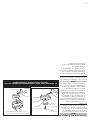
Assembly
Sub-Shield C242
(when trimmer head is in use)
1. Attach the shield extension to the
cutting attachment shield. See figure 6.
WARNING!
NEVER use this machine without
sub-shield when using a trimmer
head.
CAUTION!
Make sure the sub-shield is
completely hooked at the hook
receiver.
Sub-shield
Hook
Hook
Receiver
Cutting Attachment Shield
Outer
Tube
Socket-
Head Cap
Screw
Clamp Screw
Retaining
Nut
Cutting
Attachment Mounting
Plate
Shim
Shim
Bracket
Cutting
Attachment
Shield
Line Cutter
Figure 5A
Cutting Attachment Shield
Sub-shield with
Line Cutter
Figure 6

7
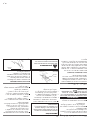
3/16-1/4 inch (4-6 mm)
Throttle Free Play
Adjust Throttle Lever Free Play
1. Loosen the air cleaner cover knob
and remove the air cleaner cover.
See Figure 9.
2. Loosen the lock nut on the cable
adjuster. See Figure 10.
Adjustments
Figure 9
The throttle lever free play should be
approximately 3/16-1/4 inch (4-6 mm). See
Figure 8. Make sure that the throttle lever
operates smoothly without binding.
If it becomes necessary to adjust the lever
free play, follow the procedures and
illustrations that follow.
Figure 8
3. Turn the cable adjuster in or out as
required to obtain proper free play
3/16-1/4 inch (4-6 mm). See Figure 10.
4. Tighten the locknut.
5. Reinstall the air cleaner cover.
Handle Bar C242
Assembly (Continued)
Figure 10
Lock
Nut
Cable
Adjuster
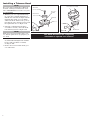
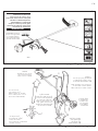
Install the handlebar:
1.
Use the 4 mm hex wrench to remove
the lower cap retaining screws from the
handlebar bracket. Remove the cap from
the bracket.
See Figure 7.
2. Position the handle on the outer tube
forward of Handle Positioning Label
as shown in Figure 7. Reassemble the
lower cap to the handlebar bracket in
the reverse order of disassembly.
3. Locate the handle in the best position for
operator comfort.
4. Firmly tighten both lower cap retaining
screws.
5. Install the protector sleeve on the outer
tube. See Figure 7.
C242
Outer Tube
Mounting Bracket
Socket-Head
Cap Screw
Handlebar
Protector Sleeve
Figure 7
Ignition Switch
Throttle
Trigger
Hanger
Shoulder Strap
Handle Positioning Label
POSITION HANDLE
FORWARD OF THIS LINE

8
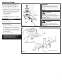
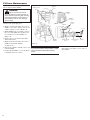
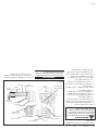
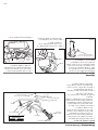
Installing a Trimmer Head
NOTE:
The C242 is shipped with Holder A, Holder B,
shaft bolt, and bolt guard installed. The shaft
bolt is a LEFT-HAND thread. Remove it by turn-
ing CLOCKWISE!
1. With the gear case output shaft facing
up, rotate the gearshaft and holder A
until the hole in holder A aligns with the
matching hole in the gear case flange,
and then lock the holder to the gear by
inserting the long end of the hex wrench
through both holes. See Figure 11A.
2. Using the combination spark plug/
screwdriver wrench, remove the shaft
bolt and bolt guard. See Figure 11A.
NOTE:
Make sure holder B is installed on the gear-
case with the splined hole engaging the gear-
case shaft.
3. Using the hex wrench to secure Holder
A , install and hand-tighten the trimmer
head (counter-clockwise to install).
See Figure 11B.
5. Remove the hex wrench from the gear
case and holder.
The C242 should now be completely
assembled to operate as a trimmer.
Hex Wrench
Hand-tighten Trimmer Head (coun-
ter-clockwise to install)
Figure 11B
Shaft Bolt
(not used)
Bolt Guard
(not used)
Gear Case
Shaft
Holder B
Holder A
Figure 11A

9
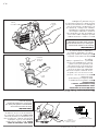
Turn the C242 upside down so the gear
case output shaft is facing UP and
remove the shaft bolt, bolt guard and
holder B from the gear case shaft.
1. Align the hole in blade holder A with the
matching hole in the gear case flange
and then temporarily lock the output
shaft by inserting a hex wrench
through both holes.
See Figure 12.
2. Fit the blade over the flange on holder
A. See Figure 13.
Installing a Blade
CAUTION!
Install the blade so its printed surface
is visible to the operator when the
brushcutter is in the normal operating
position.
WARNING!
The blade must t at against the
holder ange. The blade mounting hole
must be centered over the raised boss
on blade holder A.
IMPORTANT!
Both holders must be at against the
surface of the blade.
3. Install blade holder B on the output
shaft. See Figure 13.
4. Install the bolt guard and then the blade
retaining bolt. Using the combination
spark plug wrench/screwdriver, tighten
the bolt firmly in a counter-clockwise
direction. The holder B must fit flush
against the blade.
5. Remove the hex wrench.
Shaft Bolt
Bolt Guard
Holder B
Output Shaft
Holder A
Figure 12
Blade
Hex Wrench
Blade Holder B
Tighten the assembly (blade
not shown for clarity)
Figure 13
Output
Shaft
The C242 should now be com-
pletely assembled and
ready for use with a blade.
Hex
Wrench
WARNING!
Holder B must t ush against the
blade with the splines engaged to the
output shaft.

10
Figure 15
Primer Bulb
Return Tube
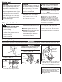
IMPORTANT!
Mix only enough fuel for your immediate
needs! If fuel must be stored longer than
30 days and oil with fuel stabilizer is
not used, it should rst be treated with a
fuel stabilizer such as STA-BIL™.
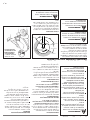
Starting the Engine
4. While holding the outer tube firmly with
left hand. Use your other hand to slowly
pull the recoil starter handle until resis-
tance is felt, then pull quickly to start the
engine.
2. Press the primer bulb until fuel can be
seen flowing in the transparent return
tube.
Make sure the
cutting
attachment
is clear of
obstructions!
IMPORTANT!
Engine ignition is controlled by a two position switch mounted on the throttle housing labeled, "I" for ON or START and "O" for OFF or STOP.
Figure 14
Figure 17
IMPORTANT!
The primer system only pushes fuel through
the carburetor. Repeatedly pressing the
primer bulb will not ood the engine with fuel.
CAUTION!
Do not pull the recoil starter to the end
of the rope travel. Pulling the recoil
starter to the end of the rope travel can
damage the starter.
Mixing Fuel
1. Place the trimmer on a flat, level surface.
2. Clear any dirt or other debris from
around the fuel filler cap.
3. Remove the fuel cap, and fill the tank
with clean, fresh fuel.
4. Reinstall the fuel filler cap and tighten
firmly.
CAUTION!
This engine is designed to operate on
a 50:1 mixture consisting of unleaded
gasoline and ISO-L-EGD or JASO FC
class 2-cycle mixing oil only. Use of
non-approved mixing oils can lead to
excessive carbon deposits.
CAUTION!
Some types of gasoline contain alcohol
as an oxygenate. Oxygenated gaso-
line may cause increased operating
temperatures. Under certain condi-
tions, alcohol-based gasoline may also
reduce the lubricating qualities of some
2-cycle mixing oils. Never use any type
of gasoline containing more than 10%
alcohol by volume! Generic oils and
some outboard oils may not be intend-
ed for use in high-performance 2-cycle
engines, and should never be used in
your Shindaiwa engine.
n Use only fresh, clean unleaded gasoline
with a pump octane of 87 or higher.
n Mix all fuel with a 2-cycle air-cooled
mixing oil that meets or exceeds
ISO-L-EGD and/or JASO FC classified
oils at 50:1 gasoline/oil ratio.
Examples of 50:1 mixing quantities
n
1 gallon of gasoline to 2.6 oz. mixing oil
n
5 liters of gasoline to 100 ml. mixing oil
Oil is a registered JASO FC
classified oil and also meets or exceeds
ISO-L-EGD performance requirements.
Shindaiwa One is recommended for use in
all Shindaiwa low emissions engines and
also includes a fuel stabilizer.
1. Slide the ignition switch to the “ON”
position. See Figure 14.
3. Set the choke lever to the CLOSED
position if engine is cold.
C242
Hand Grip
Figure 16
Closed
Filling the Fuel Tank
WARNING!
Minimize the risk of re!
n STOP engine before refueling.
n ALWAYS allow the engine to cool
before refueling!
n Wipe all spilled fuel and move the
engine at least 10 feet (3 meters)
from the fueling point and source
before restarting!
n NEVER start or operate this unit if
there is a fuel leak.
n NEVER start or operate this unit if
the carburetor, fuel lines, fuel tank
and/or fuel tank cap are damaged.
n NEVER smoke or light any res
near the engine or fuel source!
n NEVER place any ammable mate-
rial near the engine mufer!
n NEVER operate the engine without
the mufer and spark arrester in
good working condition.

11
Starting the Engine (continued)
WARNING!
Never start the engine from the oper-
ating position.
WARNING!
The cutting attachment may rotate
when the engine is started!
When the Engine Starts...
n After the engine starts, allow the en-
gine to warm up at idle 2 or 3 minutes
before operating the unit.
n After the engine is warm, pick
up the unit and clip on the shoulder
strap. See page 12.
n Advancing the throttle makes the cut-
ting attachment turn faster; releasing
the throttle permits the attachment to
stop turning. If the cutting attachment
continues to rotate when the engine
returns to idle, carburetor idle speed
should be adjusted (see "Adjusting
Engine Idle" below).
IMPORTANT!
If the engine fails to start after several at-
tempts with the choke in the closed posi-
tion, the engine may be ooded
with fuel. If ooding is suspected,
move the choke lever to the open position
and repeatedly pull the recoil starter to
remove excess fuel and start the engine.
If the engine still fails to start, refer to the
troubleshooting section of this manual.
5. When the engine starts, slowly move the
choke lever to the "OPEN" position. See
Figure 18. (If the engine stops after the
initial start, close the choke and restart.)
Idle the engine briefly before stopping
(about 2 minutes), then slide the ignition
switch to the “O” (Engine OFF) position.
Stopping the Engine
Adjusting Engine Idle
Figure 19
Figure 20
The engine must return to idle speed
whenever the throttle lever is released.
Idle speed is adjustable, and must be set
low enough to permit the engine clutch to
disengage the cutting attachment.
Idle Speed Adjustment
WARNING!
The cutting attachment must NEVER
rotate at engine idle! If the idle speed
cannot be adjusted by the procedure
described here, return the trimmer to
your Shindaiwa dealer for inspection.
1. Place the trimmer on the ground, then
start the engine, and then allow it to idle
2-3 minutes until warm.
2. If the attachment rotates when the
engine is at idle, reduce the idle speed
by turning the idle adjustment screw
counter-clockwise. See Figure 20.
3. If a tachometer is available, the engine idle
speed should be final adjusted to 3,000
(±250) RPM (min
-1
).
4. Carburetor fuel mixture adjustments are
preset at factory and cannot be serviced
in the field.
C242
OFF
Open
Idle Adjusting
Screw
Figure 18

12
NEVER operate the unit with the cut-
ting attachment shield or other protective
devices removed!
WARNING!
A cutting attachment shield or other
protective device is no guarantee of
protection against ricochet. YOU MUST
ALWAYS GUARD AGAINST FLYING
DEBRIS!
Use only authorized Shindaiwa parts and
accessories with your Shindaiwa trimmer.
Edging
Tilt the handle
about 100° to the
left (from hori-
zontal) and move
forward, holding
the trimmer verti-
cally as shown in
Figure 23.
Your Shindaiwa unit may be equipped
with one of several Shindaiwa trimmer
head models, each with features for
specific applications and/or operational
requirements.
NOTE:
For proper operation, always refer to the
instructions accompanying the trimmer head
being used. Available trimmer head styles
include:
n Semi-automatic. Trimmer line is
indexed when the operator taps the
trimmer head on the ground during
operation.
n Manual. The operator indexes line man-
ually with the grass trimmer stopped.
n Fixed. The operator must stop the unit
and add new lengths of trimmer line
manually.
n Flail. This device, designed for clearing
weeds and light brush, features three
nylon blades attached to the head by
pivots.
NOTE:
Additional hardware may be required to
mount the Fixed Line or the Flail type trim-
mer heads.
Cutting Grass—Units equipped with a trimmer head
CAUTION!
Operation at low RPM can lead to
premature clutch failure.
Trimming and
Mowing Grass
Figure 22
Checking Unit Condition
Shoulder Strap C242
Figure 21
CAUTION!
Operation of trimmer without a cutting
attachment shield and using excessive
line length can lead to premature clutch
failure.
Do not make modifications to this unit with-
out written approval from Shindaiwa, Inc.
ALWAYS make sure the cutting attach-
ment is properly installed and rmly tight-
ened before operation.
NEVER use a cracked or warped cutting
attachment: replace it with a serviceable
one.
ALWAYS make sure the cutting attach-
ment ts properly into the appropriate
attachment holder. If a properly installed
attachment vibrates, replace the attach-
ment with new one and re-check.
ALWAYS stop the engine immediately
and check for damage if you strike a for-
eign object or if the unit becomes tangled.
Do not operate with broken or damaged
equipment.
NEVER allow the engine to run at high
RPM without a load. Doing so could
damage the engine.
NEVER operate a unit with worn or
damaged fasteners or attachment holders.
CAUTION!
Do not push the rotating line into trees,
wire fences or any material that could
tangle or break line ends.
Engine Operating Speeds
Operate the unit at full throttle while cut-
ting grass.
WARNING!
Always wear a shoulder strap
or harness when operating this unit. Us-
ing a harness with a brushcutter allows
you to maintain proper control of the unit
and reduces fatigue during extended
operation.
Figure 23
IMPORTANT!
Adjust the shoulder strap so the shoulder pad
rests comfortably on the off-side shoulder and
the cutting path of the cutting attachment
is parallel to the ground. Make sure all
hooks and adjustment devices are secure.
Hold the trimmer so the trimmer head is
angled slightly into the area to be cut. To
ensure maximum trimmer-line service life,
cut only with the tip of the trimmer line.
Cut grass by swinging the trimmer from
left to right. Keep the trimmer head
horizontal. See Figure 22.
CUTTING
PATH
RETURN
PATH
Shoulder strap
required for use
with Brushcutters

13
WARNING!
n Before working with a blade-
equipped unit, always inspect and
clean the area of objects that could
interfere with or damage the blade.
n Never use a blade near sidewalks,
fence posts, buildings or other
objects that could cause injury or
damage.
n Never use a blade for purposes
other than those for which it was
designed.
n Whenever you strike a hard object
with a blade, always stop the
brushcutter and carefully inspect
the blade for damage. NEVER
OPERATE THE BRUSHCUTTER
WITH A DAMAGED BLADE!
n A blade-equipped unit must be
equipped with a bicycle-type
handlebar or barrier bar as well
as a harness or shoulder strap.
n Always make sure the cutting at-
tachment shield is properly installed
before operating this unit.
Using a Blade C242
Blade Thrust
‘Blade thrust’ is a sudden sideways or
backward motion of the brushcutter. Such
motion may occur when the blade jams or
catches on an object such as a sapling tree
or tree stump. BE CONSTANTLY ALERT
FOR BLADE THRUST AND GUARD
AGAINST ITS EFFECTS!
Brushcutter Handlebar
A brushcutter handlebar or barrier bar
helps prevent the operator from moving
forward, or the unit moving rearward,
thus preventing inadvertent bodily contact
with the blade. ALWAYS KEEP THE
HANDLEBAR OR BARRIER BAR
SECURELY IN PLACE ON THE UNIT!
Brushcutter Shoulder Strap
A shoulder strap provides additional
protection against blade thrust. In addition,
a shoulder strap gives significant support
and comfort to help ensure safe and
efficient operation.
When operating a C242 with a blade, make
sure both the handle and shoulder strap
are adjusted to the size of the operator us-
ing the unit.
Engine Operating Speeds
Operate the unit at full throttle while cut-
ting. Best fuel efficiency is obtained by
releasing the throttle when swinging back
after a cut.
n To prevent possible engine damage, do
not allow the brushcutter to run at high
speeds without a load.
n Avoid operating the engine at low
speeds. Doing so can lead to rapid
clutch wear. In addition, slow-speed
operation tends to cause grass and
debris to wrap around the cutting head.
The blade rotates counter-clockwise. For
best performance and to minimize being
stuck by debris, move the blade from right
to left while advancing on your work.
Position the blade so cuts are made be-
tween the blade’s 8 o’clock and 10 o’clock
positions (as viewed from above). DO NOT
cut between the 10 o’clock and 5 o’clock
positions.
WARNING!
When cutting wood with a saw, feed
the blade slowly—never strike or “slam”
a spinning blade against the wood.
WARNING!
DO NOT use 2-tooth or non-Shindaiwa
approved 4-tooth cutting blades with
Shindaiwa trimmers and brushcutters.
Vertical Cuts
Hold the brushcutter with the blade at
a 90° angle to the ground so the blade’s
bottom edge rotates toward the operator.
Move the blade from top to bottom through
the cut, and cut only with the bottom edge
of the blade.
Operating Units with a Blade
Figure 24
Cut on the left side of
the blade. KEEP YOUR
BODY
OUTSIDE THE PATH
OF BLADE ROTATION
Figure 25
WARNING!
When making vertical cuts, never allow
the blade to exceed waist height.
Eight
O'clock
D
O
N
O
T
C
U
T
Ten
O'clock
OK To Cut
Five
O'clock
Blade
Rotation

14
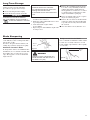
Unscrew
Fastener
Remove and
clean or replace
the element
IMPORTANT!
MAINTENANCE, REPLACEMENT OR
REPAIR OF EMISSION CONTROL
DEVICES AND SYSTEMS MAY BE
PERFORMED BY ANY REPAIR ESTAB-
LISHMENT OR INDIVIDUAL; HOWEVER,
WARRANTY REPAIRS MUST BE PER-
FORMED BY A DEALER OR SERVICE
CENTER AUTHORIZED BY SHINDAIWA
CORPORATION THE USE OF PARTS
THAT ARE NOT EQUIVALENT IN
PERFORMANCE AND DURABILITY TO
AUTHORIZED PARTS MAY IMPAIR THE
EFFECTIVENESS OF THE EMISSION
CONTROL SYSTEM AND MAY HAVE
A BEARING ON THE OUTCOME OF A
WARRANTY CLAIM.
General Maintenance
Mufer
This unit must never be operated with
a faulty or missing spark arrester or
muffler. Make sure the muffler is well
secured and in good condition. A worn
or damaged muffler is a fire hazard and
may also cause hearing loss.
Spark Plug
Keep the spark plug and wire connections
tight and clean.
Fasteners
Make sure nuts, bolts, and screws (except
carburetor adjusting screws) are tight.
Daily Maintenance
Prior to each work day, perform the following:
NOTE:
Using non-standard replacement
parts could invalidate your Shindaiwa
warranty.
n Remove dirt or debris from the
engine, check the cooling fins and air
cleaner for clogging and clean them as
necessary.
10-Hour Maintenance
Every 10 hours of operation (more fre-
quently in dusty or dirty conditions):
Remove the air cleaner element. See Figure
26. Clean or replace as necessary. To clean
element: wash it thoroughly in soap and
water. Let it dry before reinstalling the
element.
CAUTION!
Do not operate the unit if the air
cleaner or element is damaged, or if
the element is wet.
Figure 26
n Carefully remove any accumulation of
dirt or debris from the muffler or the
fuel tank. Dirt build-up in these areas
could cause engine overheating, induce
premature wear, or create a fire hazard.
n Check for loose or missing screws or
components. Make sure the cutting at-
tachment is securely fastened.
n Check the entire unit for leaking fuel or
grease.
Blades
Keep blades sharp and check blade
condition frequently. If a blade’s perfor-
mance changes suddenly, stop the engine
and check the blade for cracks or other
damage. Replace a damaged blade
IMMEDIATELY!
WARNING!
n Never repair a damaged blade by
welding, straightening, or by modify-
ing its shape. An altered blade may
break during operation, resulting in
serious personal injury.
n Blades are not interchangeable
between Shindaiwa edgers and trim-
mer/brushcutter models. Operating
any unit with a blade or attachment
not approved for that unit can be haz-
ardous and may cause serious injury.
WARNING!
Before performing any maintenance,
repair or cleaning work on the unit,
make sure the engine and cutting
attachment are completely stopped.
Disconnect the spark plug wire before
performing service or maintenance
work.
WARNING!
Non-standard parts may not operate
properly with your unit and may cause
damage and lead to personal injury.

15
50-hour Maintenance
Every 50 hours of operation
(more frequently in dusty or dirty
conditions):
n Remove and clean the cylinder cover
and clean grass and dirt from the cylin-
der fins.
n Remove the cutting attachment, cutting
attachment holder and gear shaft collar.
Remove the filler plug from the side of
the gear case and press new grease into
the gear case until old grease is pushed
out. Use only lithium-base grease such
as Shindaiwa Gear Case Lubricant or
equivalent. See Figure 28.
n Lubricate main shaft splines.
n Use a hooked wire to extract the fuel
filter from inside the fuel tank.
See Figure 29.
Old
Grease
New
Grease
Gear Shaft
Collar
Figure 28
Figure 29
CAUTION!
Make sure you do not pierce the fuel
line with the end of the hooked wire.
The line is delicate and can be dam-
aged easily.
Every 10 to 15 hours
of operation:
Remove and clean the spark plug. Adjust
the spark plug electrode gap to 0.024 - 0.028
inch (0.6 - 0.7 mm). If the spark plug must
be replaced, use only an NGK BPMR6A or
equivalent resistor type spark plug of the
correct heat range. See Figure 27.
CAUTION!
Before removing the spark plug, clean
the area around the plug to prevent
dirt and debris from getting into the
engine’s internal parts.
10/15-Hour Maintenance
Remove and replace the filter element.
Before reinstalling the new filter element,
inspect the condition of all the fuel system
components (fuel pick-up line, fuel return
line, tank vent line, tank vent, fuel cap and
fuel tank). If damage, splitting or deteriora-
tion is noted, the unit should be removed
from service until it can be inspected or
repaired by a Shindaiwa-trained service
technician.
XST021
Clean the
spark plug and
check the gap
at the electrode.
0.024–0.028 inch
(0.6–0.7 mm)
Filter Element
Hooked
Wire
Figure 27

16
135-hour Maintenance
Every 135 hours of operation,
remove and clean the muffler.
WARNING!
Never operate this trimmer
with a damaged or missing mufer or
spark arrester! Operating with missing
or damaged exhaust components is
a re hazard, and can also damage
your hearing!
1. Remove the spark plug boot.
2. With a 3 mm hex wrench remove the 1
muffler cover and 3 engine cover screws
and the engine cover. See Figure 30.
3. With a Phillips type screwdriver remove
the 5 screws holding the spark arrester
screen and cover to the muffler. See
Figure 30.
4. Remove the screen and clean it with a
stiff bristle brush.
5. With a 4 mm hex wrench remove the 3
muffler bolts and the muffler.
See Figure 30.
6. Inspect the cylinder exhaust port for any
carbon buildup.
7. Gently tap the muffler on a wood surface
to dislodge any loose carbon.
Engine Cover
Screws
IMPORTANT!
If you note excessive carbon buildup, consult
with an authorized Shindaiwa servicing
dealer.
8. Reassemble the spark arrester, muffler
and engine cover in the reverse order of
disassembly.
Figure 30
Muffler
Cover
Engine
Cover
Muffler
Cover Screw
Spark Arrester
Screen
Muffler
Gasket
Muffler
Spark Arrester
Cover
Gasket
Screws
Mufer
Screws
Outlet

17
Long Term Storage
n Remove the spark plug and pour about
1/4 ounce of 2-cycle mixing oil into the
cylinder through the spark plug hole.
Slowly pull the recoil starter 2 or 3 times
so oil will evenly coat the interior of the
engine. Reinstall the spark plug.
n Before storing the unit, repair or replace
any worn or damaged parts.
n Remove the air cleaner element from the
carburetor and clean it thoroughly with
soap and water. Let dry and reassemble
the element.
n Store the unit in a clean, dust-free area.
Whenever the unit will not be used for
30 days or longer, use the following
procedures to prepare it for storage:
n Clean external parts thoroughly.
n Drain all the fuel from the fuel tank.
IMPORTANT!
All stored fuels should be stabilized
with a fuel stabilizer such as STA-BIL™,
if oil with fuel stabilizer is not used.
CAUTION!
Gasoline stored in the carburetor
for extended periods can cause hard
starting and could also lead
to increased service and maintenance
cost.
Blade Sharpening
When the cutting edges of the blade be-
come dull, they can be resharpened with a
few strokes of a file.
In order to keep the blade in balance, all
cutting edges must be sharpened equally.
Shindaiwa Tornado™ Blade
To sharpen the cutters on a Shindaiwa Tor-
nado Blade, use a 7/32-inch round file. File
the leading edge of each tooth to a razor
edge. The top plate of each tooth should
angle back 30°.
WARNING!
Sharpen only the cutting teeth of a
blade. DO NOT alter the contour of
the blade in any way.
Multiple-tooth Circular Blade
Use a round file to maintain a radius of 0.04
to 0.06" (1 to 1.5 mm) at the base of each
tooth. Cutting edges must be offset equally
on each side.
Round
File
30°
Round
File
Figure 32
Figure 31
n Remove the remaining fuel from the
fuel lines and carburetor.
1. Prime the primer bulb until no more fuel
is passing through.
2. Start and run the engine until it
stops running.
3. Repeat steps 1 and 2 until the engine will
no longer start.

18
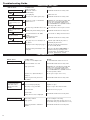
Troubleshooting Guide
ENGINE DOES NOT START
Does the engine crank?
Faulty recoil starter.
Fluid in the crankcase.
Internal damage.
Consult with an authorized servicing dealer.
NO
Good compression?
Loose spark plug.
Excess wear on cylinder, piston, rings.
Tighten and re-test.
Consult with an authorized servicing dealer.
NO
YES
Does the tank contain
fresh fuel of the proper
grade?
Refill with fresh, clean unleaded gasoline with
a pump octane of 87 or higher mixed with
a 2-cycle air cooled mixing oil that meets or
exceeds ISO-L-EGD and/or JASO FC classified
oils at 50:1 gasoline/oil ratio.
Fuel incorrect, stale or contaminated;
mixture incorrect.
NO
YES
Is fuel visible and moving
in the return line when
priming?
Check for clogged fuel filter and/or vent.
Priming pump not functioning properly.
Replace fuel filter or vent as required; restart.
Consult with an authorized servicing dealer.
NO
Is there spark at the spark
plug wire terminal?
The ignition switch is in “O” (OFF)
position.
Shorted ignition ground.
Faulty ignition unit.
Move switch to “I” (ON) position and restart.
Consult with an authorized servicing dealer.
NO
YES
YES
Check the spark plug.
If the plug is wet, excess fuel may be in
the cylinder.
The plug is fouled or improperly gapped.
The plug is damaged internally or of the
wrong size.
Crank the engine with the plug removed,
reinstall the plug and restart.
Clean and regap the plug to 0.024 - 0.028
inch (0.6 - 0.7 mm). Restart.
Replace the plug with an NGK BPMR6A or
equivalent resistor type spark plug of the
correct heat range. Set spark plug electrode
gap to 0.024 - 0.028 inch (0.6 - 0.7 mm).
YES
What To Check Possible Cause Remedy
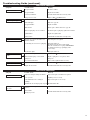
LOW POWER OUTPUT
Is the engine overheating?
Operator is overworking the unit.
Carburetor mixture is too lean.
Improper fuel ratio.
Fan, fan cover, cylinder fins dirty or
damaged.
Carbon deposits on the piston or in
the muffler.
Shorten trimmer line. Cut at a slower rate.
Consult with an authorized servicing dealer.
Refill with fresh, clean unleaded gasoline with
a pump octane of 87 or higher mixed with
a 2-cycle air cooled mixing oil that meets or
exceeds ISO-L-EGD and/or JASO FC classified
oils at 50:1 gasoline/oil ratio.
Clean, repair or replace as necessary.
Consult with an authorized servicing dealer.
Possible Cause Remedy
Engine is rough at all
speeds. May also have
black smoke and/or
unburned fuel at the
exhaust.
Clogged air cleaner element.
Loose or damaged spark plug.
Air leakage or clogged fuel line.
Water in the fuel.
Piston seizure
Faulty carburetor and/or diaphragm.
Service the air cleaner element.
Tighten or replace.
Repair or replace filter and/or fuel line.
Replace the fuel. See page 10.
Consult with an authorized servicing dealer.
Engine is knocking.
Oveheating condition.
Improper fuel.
Carbon deposits in the combustion
chamber.
Check fuel octane rating; check for presence of
alcohol in the fuel (page 10). Refuel as necessary.
Consult with an authorized servicing dealer.
What To Check
See above(Engine overheating).

19
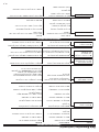
Troubleshooting Guide (continued)
ADDITIONAL PROBLEMS
Poor acceleration.
Clogged air filter.
Clogged fuel filter.
Lean fuel/air mixture.
Idle speed set too low.
Symptom Possible Cause Remedy
Engine stops abruptly.
Switch turned off.
Fuel tank empty.
Clogged fuel filter.
Water in fuel.
Shorted spark plug or loose terminal.
Ignition failure.
Piston seizure.
Reset the switch and and restart.
Refuel. See page 10.
Replace fuel filter.
Drain; replace with clean fuel. See page 10.
Clean and replace spark plug, tighten the terminal.
Replace the ignition unit.
Consult with an authorized servicing dealer.
Engine difficult to shut off.
Ground (stop) wire is disconnected or
switch is defective.
Overheating due to incorrect spark plug.
Overheated engine.
Test and replace as required.
Idle engine until cool.
Clean and regap the plug to 0.024 - 0.028
inch (0.6 - 0.7 mm). Correct plug: NGK BPMR6A
or equivalent resistor type spark plug of the
correct range.
Idle engine until cool.
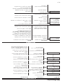
Cutting attachment rotates
at idle.
Engine idle too high.
Broken clutch spring or worn clutch
spring boss.
Loose attachment holder.
Engine will not idle down.
Engine idle set too high.
Engine has an air leak.
Clean the air filter.
Replace the fuel filter.
Consult with an authorized servicing dealer.
Adjust: 3,000 ( 250) RPM (min )
-1
Set Idle: 3,000 ( 250) RPM (min )
Replace spring/shoes as required, check
idle speed.
Inspect and re-tighten holders securely.
-1
Set Idle: 3,000 ( 250) RPM (min )
Consult with an authorized servicing dealer.
-1
ADDITIONAL PROBLEMS
Symptom Possible Cause Remedy
Excessive vibration.
Warped or damaged cutting attachment.
Loose gearcase.
Bent main shaft/worn or damaged
bushings.
Trimmer line not wound properly on spool.
Inspect and replace attachment as required.
Tighten gearcase securely.
Inspect and replace as necessary.
Rewind trimmer line.
Cutting attachment will
not rotate.
Shaft not installed in powerhead or
gearcase.
Broken shaft.
Damaged gearcase.
Inspect and reinstall as required.
Consult with an authorized servicing dealer.

Shindaiwa Inc.
11975 S.W. Herman Rd.
Tualatin, Oregon 97062
Telephone: 503 692-3070
Fax: 503 692-6696
www.shindaiwa.com
Shindaiwa Corporation
6-2-11 Ozuka-Nishi
Asaminami-Ku, Hiroshima
731-3167, Japan
Telephone: 81-82-849-2220
Fax: 81-82-849-2481
Shindaiwa Corporation warrants to the initial purchaser and each
subsequent owner, that this utility equipment engine (herein engine)
is designed, built and equipped to conform at the time of initial sale,
to all applicable regulations of the U.S. Environmental Protection
Agency (EPA), and that the engine is free of defects in materials and
workmanship that would cause this engine to fail to conform with EPA
regulations during its warranty period. This emission warranty is ap-
plicable in all States, except the State of California.
For parts listed under PARTS COVERED, the dealer authorized by
Shindaiwa Corporation will, at no cost to you, make the necessary
diagnosis, repair, or replacement of any defective emission-related
component to ensure that the engine complies with applicable U.S.
EPA regulations.
MANUFACTURERS WARRANTY COVERAGE
When sold within the U.S., this engine’s emission control system is warranted
for a period of two (2) years from the date this product is first delivered to the
original retail purchaser.
OWNER’S WARRANTY RESPONSIBILITIES
As the engine owner, you are responsible for the performance of the required
maintenance listed in your owner’s manual. Shindaiwa Corporation recom-
mends that you retain all receipts covering maintenance on your engine, but
Shindaiwa Corporation cannot deny a warranty claim solely for the lack of
receipts or for your failure to ensure the performance of all scheduled mainte-
nance.
As the engine owner, you should however be aware that Shindaiwa Corpora-
tion may deny your warranty coverage if your engine or a part has failed due
to abuse, neglect, improper maintenance or unapproved modifications.
You are responsible for presenting your engine to the nearest dealer autho-
rized by Shindaiwa Corporation when a problem exists.
If your Shindaiwa Dealer is unable to answer questions regarding your war-
ranty rights and responsibilities, you should then contact your Shindaiwa
Distributor.
For the name and telephone number of the Shindaiwa Distributor in your area,
please call Shindaiwa Inc. at (503) 692-3070 between the hours of 8:00 AM and
5:00 PM Pacific Standard Time.
PARTS COVERED
Listed below are the parts covered by the Federal Emission Design and Defect
Warranty. Some parts listed below may require scheduled maintenance and
are warranted up to the first scheduled replacement of that part. The war-
ranted parts include:
1. Carburetor Internal Components
• Valve Assembly-throttle, Jet, Metering Diaphragm
2. Ignition System Components
• Ignition Coil
• Flywheel Rotor
The emission control system for your particular Shindaiwa engine may also
include certain related hoses and connectors.
The following statement only applies to United States and its territories
Shindaiwa Corporation
Federal Emission Design And Defect Limited Warranty
Utility And Lawn And Garden Engines
LIMITATIONS
The Federal Emission Design and Defect Warranty shall not cover
any of the following:
(a) conditions resulting from tampering, misuse, improper
adjustment (unless they were made by the dealer or service
center authorized by Shindaiwa Corporation during a warranty
repair), alteration, accident, failure to use the recommended
fuel and oil, or not performing required maintenance services,
(b) the replacement parts used for required maintenance services,
(c) consequential parts used for required maintenance services,
(d) diagnosis and inspection fees that do not result in eligible war-
ranty service being performed, and
(e) any non-authorized replacement part, or malfunction of autho-
rized parts due to use of non-authorized parts.
MAINTENANCE AND REPAIR REQUIREMENTS
You are responsible for the proper use and maintenance of the engine. You
should keep all receipts and maintenance records covering the performance of
regular maintenance in the event questions arise. These receipts and mainte-
nance records should be transferred to each subsequent owner of the engine.
Shindaiwa Corporation reserves the right to deny warranty coverage if the
owner has not properly maintained the engine. Shindaiwa Corporation will not
deny warranty repairs, however, solely because of the lack of repair, mainte-
nance or failure to keep maintenance records.
MAINTENANCE, REPLACEMENT OR REPAIR OF EMISSION CONTROL
DEVICES AND SYSTEMS MAY BE PERFORMED BY ANY REPAIR ESTAB-
LISHMENT OR INDIVIDUAL; HOWEVER, WARRANTY REPAIRS MUST
BE PERFORMED BY A DEALER OR SERVICE CENTER AUTHORIZED BY
SHINDAIWA CORPORATION THE USE OF PARTS THAT ARE NOT EQUIVA-
LENT IN PERFORMANCE AND DURABILITY TO AUTHORIZED PARTS MAY
IMPAIR THE EFFECTIVENESS OF THE EMISSION CONTROL SYSTEM AND
MAY HAVE A BEARING ON THE OUTCOME OF A WARRANTY CLAIM.
If other than the parts authorized by Shindaiwa Corporation are used for
maintenance replacements or for the repair of components affecting emission
control, you should assure yourself that such parts are warranted by their
manufacturer to be equivalent to the parts authorized by Shindaiwa Corpora-
tion in their performance and durability.
OBTAINING WARRANTY SERVICE
All repairs qualifying under this limited warranty must be performed by a
dealer authorized by Shindaiwa Corporation
If any emission-related part is found defective during the warranty period, it is
your responsibility to present the product to an authorized Shindaiwa dealer.
Bring your sales receipts showing the date of purchase for this engine. The
dealer authorized by Shindaiwa Corporation will perform the necessary repairs
or adjustments within a reasonable amount of time and furnish you with a copy
of the repair order. All parts and accessories replaced under this warranty
become the property of Shindaiwa Corporation
To locate an authorized Shindaiwa dealer near you, contact your Shindaiwa
Distributor. For the name and telephone number of the Shindaiwa Distributor
in your area, please call Shindaiwa Inc. at (503) 692-3070 between the hours of
8:00 AM and 5:00 PM Pacific Standard Time.
THIS WARRANTY IS ADMINISTERED BY
Shindaiwa Inc.
11975 S.W. Herman Rd.
Tualatin OR. 97062
(503) 692-3070
©2007 Shindaiwa, Inc.
Part Number 81644
Revision 1/07
Shindaiwa is a registered trademark
of Shindaiwa, Inc.
Specications subject to change without notice.
Page is loading ...
Page is loading ...
Page is loading ...
Page is loading ...
Page is loading ...
Page is loading ...
Page is loading ...
Page is loading ...
Page is loading ...
Page is loading ...
Page is loading ...
Page is loading ...
Page is loading ...
Page is loading ...
Page is loading ...
Page is loading ...
Page is loading ...
Page is loading ...
Page is loading ...
Page is loading ...
-
 1
1
-
 2
2
-
 3
3
-
 4
4
-
 5
5
-
 6
6
-
 7
7
-
 8
8
-
 9
9
-
 10
10
-
 11
11
-
 12
12
-
 13
13
-
 14
14
-
 15
15
-
 16
16
-
 17
17
-
 18
18
-
 19
19
-
 20
20
-
 21
21
-
 22
22
-
 23
23
-
 24
24
-
 25
25
-
 26
26
-
 27
27
-
 28
28
-
 29
29
-
 30
30
-
 31
31
-
 32
32
-
 33
33
-
 34
34
-
 35
35
-
 36
36
-
 37
37
-
 38
38
-
 39
39
-
 40
40


Ask a question and I''ll find the answer in the document
Finding information in a document is now easier with AI
in other languages
- español: Shindaiwa 81644 Manual de usuario