Frigidaire FPGC3087MS Installation guide

Category
Cookers
Type
Installation guide

The Frigidaire FPGC3087MS gas cooktop boasts a sleek and modern design, featuring stainless steel construction for durability and easy cleaning. Equipped with four burners, including a powerful 15,000 BTU burner, this cooktop offers versatile cooking options for all your culinary creations. Its electronic ignition ensures quick and effortless ignition, eliminating the need for matches or lighters. Additionally, the cooktop's continuous grates allow for easy movement of pots and pans across the cooking surface, enhancing your cooking experience.

The Frigidaire FPGC3087MS gas cooktop boasts a sleek and modern design, featuring stainless steel construction for durability and easy cleaning. Equipped with four burners, including a powerful 15,000 BTU burner, this cooktop offers versatile cooking options for all your culinary creations. Its electronic ignition ensures quick and effortless ignition, eliminating the need for matches or lighters. Additionally, the cooktop's continuous grates allow for easy movement of pots and pans across the cooking surface, enhancing your cooking experience.

GAS COOKTOP INSTALLATION INSTRUCTIONS
WARNING


FOR YOUR SAFETY:
 

WHAT TO DO IF YOU SMELL GAS:
 
 
 

 
 


English - pages 1-10
French - pages 11-20
All dimensions are stated in inches and (cm).
Dimension H includes a 5" (12.7 cm) space underneath the cooktop for connection to gas
supply line.

Printed in Canada
PRODUCT DIMENSIONS
MODEL     
30" G     
CUTOUT DIMENSIONS
  
COOKTOP
MODEL MINIMUM  MINIMUM 
30" G   19
1
/
8
  
H
A
B
E
30” Min. *
(76.2 cm)
F
D
C
G
Figure 1

Cutout
Dimensions

Dimensions
INSTALLATION AND SERVICE MUST BE PERFORMED BY A



GAS COOKTOP INSTALLATION INSTRUCTIONS
2

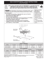
1. Read all instructions contained in these
installation instructions before installing the
cooktop.
2. Remove all packing material before connecting
the electrical supply to the cooktop.
3. O b s e r v e a l l g o v e r n i n g c o d e s a n d
ordinances.
4. Be sure to leave these instructions with the
consumer.
5. Note: For operation at 2000 ft. elevations
above sea level, appliance rating shall be
reduced by 4 percent for each additional
1000 ft.

Keep these instructions with your Use and Care
Guide for future reference.
IMPORTANT SAFETY
INSTRUCTIONS
Installation of this cooktop must conform with
local codes or, in the absence of local codes,
with the National Fuel Gas Code ANSI Z223.1
in the United States, or in Canada, with the
Canadian Fuel Gas Code, CAN/CGA B149.1
and CAN/CGA B149.2.

home installation must conform with the
Manufactured Home Construction and
Safety Standard, title 24 CFR, part 3280
[Formerly the Federal Standard for Mobile
Home Construction and Safety, title 24, HUD
(part 280)] or, when such standard is not
applicable, the Standard for Manufactured
Home Installation, ANSI/NCSBCS A225.1 or
with local codes where applicable.

International. As with any appliance using
gas and generating heat, there are certain
safety precautions you should follow. You will
Use and Care Guide, read it
carefully.
       

a range, shall not be used in conjunction with
gas ranges other than when the hood and
range have been designed, tested and listen
by an independent test laboratory for use in
combination with each other.




grounded in accordance with local codes


edition in the United States, or in Canada,
with the Canadian Electrical Code, CSA







Do not store items of interest to children
Children
could be seriously burned climbing on the
cooktop to reach items.





 Excessive flame is
hazardous.

 Prolonged use of the
cooktop without adequate ventilation can be
hazardous.
Do not store or use gasoline or other


could result.
WARNING




GAS COOKTOP INSTALLATION INSTRUCTIONS
3
Figure 2 – CABINET DESIGN
CAUTION
To eliminate

from reaching over heated
surfaces, cabinet storage
space located above the
cooktop should be avoided.
If cabinet storage is
provided, risk can be
reduced by installing a
range hood that projects
horizontally a minimum of
5" (12.7 cm) beyond the
bottom of the cabinets.
2
½
" (6.4 cm) Minimum
Distance Between Rear
Edge of Cutout and
Nearest Combustible
Surface Above Countertop.
Clearance
30" (76.2 cm)
Min. Clearance
Between the Top
of the Cooking
Platform and
Unprotected

Cabinet
13" (33 cm)
Max. Depth
For Cabinet
Installed
Above
Cooktop.
MODEL A 
Clearance
from Left Side

Clearance from
Right Side
30" Cooktop 30" (76.2 cm) 9" (22.9 cm) 9" (22.9 cm)
2¼" (5.7 cm) Min.
From Counter Edge
to Front Edge of
Cutout.
If a drawer is present underneath, allow at least
6½" (16.5 cm) of clearance below the counter
top. Make sure there will be no interference with
gas or electrical connection.
CAUTION

the drawer.
GAS COOKTOP INSTALLATION INSTRUCTIONS
4
CUTOUT DIMENSIONS (INCHES (CM))
OVEN
SIZE
  
    
30" (76.2) 27 ¼" (69,2 cm) 28¼" (71.8) 28½" (72.4) 29" (73.7) 23½" (59.7)
27" (68.6) 27 ¼" (69,2 cm) 28¼" (71.8) 24
7
/
8
" (63.2) 25¼" (64.1) 23½" (59.7)
* If no cooktop is
installed directly
over the oven
unit, 5” (12.7cm)
maximum is
allowed.
Typical Under Counter Installation of an Electric Built-in Oven
with a Cooktop Mounted Above
Cut an opening in wood base
minimum 4” (10.2 cm) x 4” (10.2 cm)
to route armored cable to junction box.
4 1/2” (11.4 cm)
Max.*
208/240 Volt
grounded junction
box for built-in
oven.
All mounting
hardware must be used to
secure the built-in oven to
the cabinets. Refer to the
built-in oven installation
instructions.

to isolate the unit from adjoining
cabinets. Panel height should
allow for installation of approved
cooktop models. See “Typical
Gas Cooktop Installation Over
an Electric Built-in Oven Installed
Under the Counter” on next page.
36”
(91.4 cm) Min.
Junction box
must be located
approx. 3" to the
left of the built-in
oven cutout.
This cooktop may be
installed over certain
built-in electric oven
models.
Figure 3
Use 3/4” (1.9 cm)
plywood, installed on

with toe plate. Base
must be capable
of supporting 150
pounds (68 kg) for
27" models and 200
pounds (90 kg) for
30" models.
Unit will
overlap
cutout
(minimum)
edges by 1"
(2.5cm)
GAS COOKTOP INSTALLATION INSTRUCTIONS
5
Typical Gas Cooktop Installation Over
an Electric Built-in Oven Installed Under the Counter
FRONT VIEW
SIDE VIEW
Figure 4

GAS COOKTOP
GAS COOKTOP

Pressure
Regulator
Flare Union
Flare Union
Flexible Connector
Cabinet sides

Manifold Pipe
Manual Shutoff Valve
(To be accessible
for shut-off valve
operation)
18”
(45.7 cm)
Max.
Approx.
6½”
(16.5 cm)
GAS COOKTOP INSTALLATION INSTRUCTIONS
6
Once the cooktop is installed in the counter
opening, you must clamp the unit down as shown.
To clamp down, insert an angle bracket into the
slot on each side of the unit as shown. Run thumb
screw up through the bracket, up against the
bottom of the counter. Tighten until the unit draws
down and is secure.

This cooktop is designed to operate on natural
gas at 4" of manifold pressure only.
A pressure regulator is connected in series with
the manifold on the cooktop and must remain in
series with the supply line.
 the maximum inlet
pressure to the regulator must be no more than

For checking the regulator, the inlet pressure
must be at least 1" (or 2.5 kPa) greater than the
regulator manifold pressure setting. The regulator
is set for 4" of manifold pressure, the inlet
pressure must be at least 5".
The gas supply line to the range should be 1/2" or
3/4" pipe.

This appliance can be used with Natural gas or

use with natural gas.


GAS CONVERSION".
The conversion must be performed by a

the kit instructions and all local codes and
requirements. Failure to follow instructions could
result in serious injury or property damage. The

responsibility for the conversion.
WARNING
Failure to make the appropriate
conversion can result in serious personal injury
and property damage.
 Remove all packing material and
literature from cooktop before connecting gas and
electrical supply to cooktop.


1. Visually inspect the cooktop for damage.
2. Set the cooktop into the countertop cutout.






NOTE: Do not use caulking compound; cooktop
should be removable for service when needed.

A Granite Countertop Installation kit # 903103-
9010 can be ordered through an Electrolux Service
Center.

Figure 5


Angle
Bracket
Seal

Screw
Figure 6
GAS COOKTOP INSTALLATION INSTRUCTIONS
7
The supply line must be equipped with an
approved manual shutoff valve. This valve should
be located in the same room as the cooktop
and should be in a location that allows ease of
opening and closing. Do not block access to
the shutoff valve. The valve is for turning on or
shutting off gas to the appliance.
Once regulator is in place, open the shutoff valve

to move through the gas line.
 After connecting the cooktop to
the gas supply, check the system for leaks with a
manometer. If a manometer is not available, turn
on the gas supply and use a liquid leak detector
(or soap and water) at all joints and connections
to check for leaks.
WARNING

leaks from gas connections. Checking for leaks

Tighten all connections if necessary to prevent
gas leakage in the cooktop or supply line.
 after
connecting the cooktop to the gas supply to be
sure the cooktop manifold pipe has not moved. A
misalignment could cause the valve stems to rub
on the control panel, resulting in a gas leak at the
valve.

 from the gas supply piping
system during any pressure testing of that system
at test pressures greater than 1/2 psig (3.5 kPa or
14"water column).

system by closing its individual manual shutoff
valve during any pressure testing of the gas
supply piping system at test pressures equal to or
less than 1/2 psig (3.5 kPa or 14" water column).

Install the pressure regulator with the arrow on the
regulator pointing up toward the unit in a position
where you can reach the access cap.
WARNING
Do not make the connection too
tight. The regulator is die cast. Overtightening
may crack the regulator resulting in a gas leak


supply pipe to the pressure regulator in the
following order:
1. manual shutoff valve
2. 1/2" (1.3 cm) nipple



6. 1/2" (1.3 cm) nipple
7. pressure regulator
Use pipe-joint compound made for use with


certain connectors are not kinked.
Figure 8
Shutoff Valve -
Open position
to appliance
to gas supply line
All connections must be wrench-tightened
Figure 7
Flare
Union
Flare
Union
GAS FLOW
Manual
Shutoff
Valve
Pressure
Regulator
On
Off
Flexible
Connector
Access
Cap
Nipple Nipple
GAS COOKTOP INSTALLATION INSTRUCTIONS
8

Refer to the Use and Care Guide packaged with
the cooktop for operating instructions and for care
and cleaning of your cooktop.
 
 

 
Operation of electric igniters should be
checked after cooktop and supply line
connectors have been carefully checked for
leaks and the cooktop has been connected to
electric power.
:
A. Push in and turn a surface burner knob

ticking noise; this is the sound of the
electric ignitor which lights the burner.
B. After the burner lights, turn to the desired

set at a particular mark. Use the marks as


120 volt, 60 Hertz, properly grounded branch
circuit protected by a 15 amp circuit breaker or
time delay fuse. Do not use an extension cord

Grounding Instructions
IMPORTANT Please read carefully.


The power cord of this appliance is equipped with
a 3-prong (grounding) plug which mates with a
standard 3-prong grounding wall receptacle (see
Figure 9) to minimize the possibility of electric
shock hazard from the appliance.
The wall receptacle and circuit should be checked

receptacle is properly grounded.

installed, it is the personal responsibility and
obligation of the consumer to have it replaced by
a properly grounded 3-prong wall receptacle.
Preferred Method
Grounding type
wall receptacle
Do not, under any
circumstances,



Power supply
cord with 3-prong
grounding plug.
Do not, under any circumstances, cut or


WARNING
Disconnect electrical supply cord
from wall receptacle before servicing cooktop.
Figure 9
GAS COOKTOP INSTALLATION INSTRUCTIONS
9
4 


ignites.
b. Quickly 
c. If burner goes out, reset control to OFF.
d. Remove the surface burner control knob.
e. Insert a thin-bladed screwdriver into the
hollow valve stem and engage the slotted
screw inside. Flame size can be increased
or decreased with the turn of the screw. Turn





without going out.


Note: On the dual valve the low setting of each
portion should be adjusted individually.

to turn until only the inner portion of the dual
burner stays on.
b. Quickly 
c. If burner goes out, reset control to OFF.
d. Remove the surface burner control knob.

size can be increased or decreased with the
turn of the screw B. Use screw A to adjust the

burner. Turn the screw counterclockwise to




Flame should be as small as possible without
going out.
Note: Air mixture adjustment is not required on
surface burners.

Make sure all controls are left in the OFF position.

air to the cooktop is unobstructed.

The serial plate is located on the underside of the
cooktop.

your range, always be sure to include the model
and serial numbers and a lot number or letter from
the serial plate of your cooktop.
Your serial plate also tells you the rating of the
burners, the type of fuel and the pressure the
cooktop was adjusted for when it left the factory.

Read the Before You Call for Service Checklist
and operating instructions in your Use and Care
Guide. It may save you time and expense. The
list includes common occurrences that are not the
result of defective workmanship or materials in
this appliance.
Refer to the warranty in your Use and Care
Guide for our service phone number and address.
Please call or write if you have inquiries about
your product and/or need to order parts.
Figure 10
Regular
Burner

Dual
Burner

A
B
Hollow

Stem
Clockwise
Counterclockwise
Note: Air mixture adjustment is not required on
surface burners.
INSTRUCTIONS D'INSTALLATION POUR PLAQUE DE CUISSON À GAZ
20
SCHÉMA DE CÂBLAGE
  • Page 1 1
  • Page 2 2
  • Page 3 3
  • Page 4 4
  • Page 5 5
  • Page 6 6
  • Page 7 7
  • Page 8 8
  • Page 9 9
  • Page 10 10
  • Page 11 11
  • Page 12 12
  • Page 13 13
  • Page 14 14
  • Page 15 15
  • Page 16 16
  • Page 17 17
  • Page 18 18
  • Page 19 19
  • Page 20 20

Frigidaire FPGC3087MS Installation guide

Category
Cookers
Type
Installation guide

The Frigidaire FPGC3087MS gas cooktop boasts a sleek and modern design, featuring stainless steel construction for durability and easy cleaning. Equipped with four burners, including a powerful 15,000 BTU burner, this cooktop offers versatile cooking options for all your culinary creations. Its electronic ignition ensures quick and effortless ignition, eliminating the need for matches or lighters. Additionally, the cooktop's continuous grates allow for easy movement of pots and pans across the cooking surface, enhancing your cooking experience.

Ask a question and I''ll find the answer in the document

Finding information in a document is now easier with AI

in other languages