
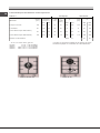
PMG 41 DCDR SF
PMG 42 SF
English
Operating Instructions
HOB
Français
Mode d’emploi
TABLE DE CUISSON
Español
Manual de instrucciones
ENCIMERA
Italiano
Istruzioni per l’uso
PIANO
Sommario
Istruzioni per l’uso,1
Avvertenze,3
Assistenza,6
Descrizione dell’apparecchio,8
Installazione,11
Avvio e utilizzo,15
Precauzioni e consigli,16
Manutenzione e cura,17
Anomalie e rimedi,17
Contents
Operating Instructions,1
Warnings,3
Assistance,6
Description of the appliance,8
Installation,18
Start-up and use,22
Precautions and tips,22
Maintenance and care,23
Troubleshooting,23
Sommaire
Mode d’emploi,1
Avertissements,4
Assistance,6
Description de l’appareil,9
Installation,24
Mise en marche et utilisation,29
Précautions et conseils,29
Nettoyage et entretien,31
Anomalies et remèdes,31
Sumario
Manual de instrucciones,1
Advertencias,4
Asistencia,6
Descripción del aparato,9
Instalación,32
Puesta en funcionamiento y uso,36
Precauciones y consejos,37
Mantenimiento y cuidados,38
Anomalías y soluciones,38
Page is loading ...

3
Avvertenze
ATTENZIONE: Questo apparecchio e le sue parti
accessibili diventano molto caldi durante l’uso.
Bisogna fare attenzione ed evitare di toccare gli
elementi riscaldanti. Tenere lontani i bambini inferiori
agli 8 anni se non continuamente sorvegliati. Il
presente apparecchio può essere utilizzato dai
bambini a partire dagli 8 anni e da persone con
ridotte capacità siche, sensoriali o mentali oppure
con mancanza di esperienza e di conoscenza se
si trovano sotto adeguata sorveglianza oppure se
sono stati istruiti circa l’uso dell’apparecchio in modo
sicuro e se si rendono conto dei pericoli correlati. I
bambini non devono giocare con l’apparecchio. Le
operazioni di pulizia e di manutenzione non devono
essere effettuate dai bambini senza sorveglianza.
ATTENZIONE: Lasciare un fornello incustodito con
grassi e olii può essere pericoloso e può provocare un
incendio. Non bisogna MAI tentare di spegnere una
amma/incendio con acqua, bensì bisogna spegnere
l’apparecchio e coprire la amma per esempio con
un coperchio o con una coperta ignifuga.
ATTENZIONE: Rischio di incendio: non lasciare
oggetti sulle superci di cottura.
Non utilizzare mai pulitori a vapore o ad alta pressione
per la pulizia dell’apparecchio.
L’apparecchio non è destinato a essere messo in
funzione per mezzo di un temporizzatore esterno
oppure di un sistema di comando a distanza
separato.
ATTENZIONE: l’uso di protezioni del piano
inappropriate può causare incidenti.
ATTENZIONE: In caso di danneggiamento del piano
in vetro:
- spegnere immediatamente tutti i bruciatori e
eventuali elementi riscaldanti elettrici e scollegare
l’apparecchio dalla rete elettrica
- non toccare la superce dell’apparecchio
Warnings
WARNING: The appliance and its accessible parts
become hot during use. Care should be taken to
avoid touching heating elements. Children less than 8
years of age shall be kept away unless continuously
supervised. This appliance can be used by children
aged from 8 years and above and persons with
reduced physical, sensory or mental capabilities or
lack of experience and knowledge if they have been
given supervision or instruction concerning use of the
appliance in a safe way and understand the hazards
involved. Children shall not play with the appliance.
Cleaning and user maintenance shall not be made
by children without supervision.
WARNING: Unattended cooking on a hob with fat or
oil can be dangerous and may result in re. NEVER
try to extinguish a re with water, but switch off the
appliance and then cover ame e.g. with a lid or a
re blanket.
WARNING: Danger of re: do not store items on the
cooking surfaces.
Never use steam cleaners or pressure cleaners on
the appliance.
The appliance is not intended to be operated by
means of an external timer or separate remote
control system.
CAUTION: the use of inappropriate hob guards can
cause accidents.
CAUTION: In case of hotplate glass breakage:
- shut immediately off all burners and any electrical
heating element and isolate the appliance from the
power supply
- do not touch the appliance surface
Page is loading ...
Page is loading ...
Page is loading ...
Page is loading ...

8
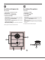
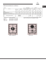
Descrizione dell’apparecchio
Vista d’insieme
1 Griglie di appoggio per RECIPIENTI DI COTTURA
2 BRUCIATORI GAS
3 Manopole di comando dei BRUCIATORI GAS
4 Candela di accensione dei BRUCIATORI GAS
5 DISPOSITIVO DI SICUREZZA
• BRUCIATORI GAS sono di diverse dimensioni e potenze. Scegliete quello
più adatto al diametro del recipiente da utilizzare.
• Manopole di comando dei BRUCIATORI GAS per la regolazione della
amma o della potenza.
• Candela di accensione dei BRUCIATORI GAS permette l’accensione
automatica del bruciatore prescelto.
• DISPOSITIVO DI SICUREZZA in caso di spegnimento accidentale della
amma, interrompe l’uscita del gas.
! L’asola più grande va inserita nella candela accensione.
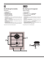
Description of the appliance
Overall view
1 Support Grid for COOKWARE
2 GAS BURNERS
3 Control Knobs for GAS BURNERS
4 Ignition for GAS BURNERS
5 SAFETY DEVICES
• GAS BURNERS differ in size and power. Use the diameter of the cookware
to choose the most appropriate burner to cook with.
• Control Knobs for GAS BURNERS adjust the power or the size of the
ame.
• GAS BURNER IGNITION enables a specic burner to be lit automatically.
• SAFETY DEVICE stops the gas flow if the flame is accidentally
extinguished.
! The largest slot should be inserted into the ignition.
4
5
1
2
3
Page is loading ...
Page is loading ...
Page is loading ...
Page is loading ...
Page is loading ...
Page is loading ...
Page is loading ...
Page is loading ...
Page is loading ...

18
GB
Installation
! Before operating your new appliance please read this instruction booklet
carefully. It contains important information for safe use, installation and care
of the appliance.
! Please keep these operating instructions for future reference. Pass them on
to possible new owners of the appliance.
The hobs have the following technical characteristics:
-Category I3+/I3P
- Class 1: all models whose edges are higher than/equal to 73,5 mm (see
following page, detail H3).
- Class 3: all models whose edges are lower than/equal to 73,5 mm (see
following page, detail H1 and H2).
Positioning
! Keep packaging material out of the reach of children. It can become a choking
or suffocation hazard (see Precautions and tips).
! The appliance must be installed by a qualied professional according to the
instructions provided. Incorrect installation may cause harm to people and
animals or may damage property.
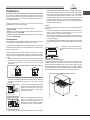
! This unit may be installed and used only in permanently ventilated rooms
in accordance with current national regulations. The following requirements
must be observed:
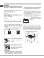
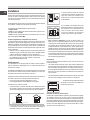
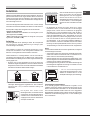
• The room must be equipped with an air extraction system that expels
any combustion fumes. This may consist of a hood or an electric fan that
automatically starts each time the appliance is switched on.
In a chimney stack or branched flue.
(exclusively for cooking appliances)
Directly to
the Outside
• The room must also allow proper air circulation, as air is needed for
combustion to occur normally. The ow of air must not be less than 2 m
3
/h
per kW of installed power.
The air circulation system may take air directly
from the outside by means of a pipe with an
inner cross section of at least 100 cm
2
; the
opening must not be vulnerable to any type
of blockages.
The system can also provide the air needed for
combustion indirectly, i.e. from adjacent rooms
tted with air circulation tubes as described
above. However, these rooms must not be
communal rooms, bedrooms or rooms that
may present a re hazard.
• Liquid petroleum gas sinks to the oor as it is heavier than air. Therefore,
rooms containing LPG cylinders must also be equipped with vents to allow
gas to escape in the event of a leak. As a result LPG cylinders, whether
partially or completely full, must not be installed or stored in rooms or
A
Examples of
ventilation holes
for comburant air.
Enlarging the ventilation slot
between window and floor.
Adjacent
Room
Room to be
Vented
storage areas that are below ground level (cellars, etc.). It is advisable to
keep only the cylinder being used in the room, positioned so that it is not
subject to heat produced by external sources (ovens, replaces, stoves,
etc. ) which could raise the temperature of the cylinder above 50°C.
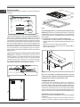
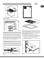
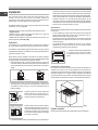
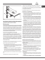
Fitting the appliance
The following precautions must be taken when installing the hob:
• Kitchen cabinets adjacent to the appliance and higher than the worktop
must be situated from the edge of the rack min. 22mm at the side and
65mm at the back (see diagram).
• If the hob is installed beneath a wall cabinet, the latter must be situated
min. 650mm from the upper edge of the hob (see diagram).
• Hoods must be installed according to their relative installation instruction
manuals and at a minimum distance of 650 mm from the hob.
• Place the wall cabinets adjacent to the hood
at a minimum height of 420 mm from the hob
(see gure).
Installation
Make sure you take all the necessary precautions to guarantee proper
installation in compliance with the applicable norms in force regarding accident-
prevention for electrical connection.For the correct operation of the appliance
when built into the cabinet, it is vital that the minimum distances illustrated in
Fig. 1 be respected. The hob features a type Y degree of protection against
overheating in compliance with norms.All surfaces adjacent to the cabinet and
the back panel should be made of materials resistant to a temperature of 65°C.
Min.
700
mm
50
mm
50
mm
Fig.1
600mm min.
420mm min.
650mm min.

GB
19
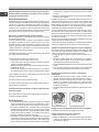
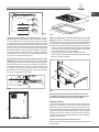
Securing the appliance to the cabinet
There are three different groups of appliance as far as installation is concerned:
BUILT-IN HOB
HEIGHT= STEEL THICKNESS
BUILT-IN HOB
STEEL TICKNESS <HEIGHT <58mm
SIT ON - ON HOB
HEIGHT >58mm
Fig.2
1- Built-in hobs to be slotted in (Class 3 - see g.2 detail H1). In this case
it is necessary to make a hole in the worktop whose measurements match
those of the hob. The measurement at the side should be reduced by 2 cm
so as to ensure that 1 cm of the perimeter of the hob overlaps with and rests
on top of the supporting surface. To slot in the hob ush with the worktop, the
cut-out on this supporting surface must be lowered (see gure 3a), so that
both the edge of the hob and the seal under it can be positioned there. Before
tting the hob to the worktop, position the seal G provided along the perimeter
of the hob, as illustrated in gure 3b.Brackets for xing hobs to the cabinet
have been provided, and these should be tted as shown in detail S (g.3a).
2-Built-in hobs (Class 3) with edges lower than 58 mm (see g.2 detail
H2). To install this type of hob, a hole large enough to accommodate the
whole lower casing of the appliance must be made on the worktop intended
to be under the hob. Remember to leave a gap of at least 1 cm between the
lower casing and the worktop around the whole perimeter of the appliance
(the underside of the casing can,however, touch the surface below it). To
t the appliances, follow the instructions given above in point 1 or use any
supplementary instruction leaet that is provided in special cases.3- Sit-on
hobs (Class 1) with edges higher
Fig.3a
G
Fig.3b
Y - 20mm
X - 20mm
X
Y
Fig.3c
3-Sit-on hobs (Class 1) with edges higher than 58 mm
(see detail H3). In this case, the lower casing of the hob does not protrude
further than the edge of the appliance.
Even when the hob is resting on the worktop, it will sufce to leave space for
the gas supply tube and electricity supply cable. To t this type of hob, follow
the instructions below (see gure):
• Fix the two screws provided “A” at a distance from the back panel as
shown in gure, leaving the heads of the screws sticking out of the wood
by 1.5 mm.
• Hook the hob onto the two screws “A” and push it towards the back.
• Fix the appliance to the cabinet at the rear, using the two brackets “B” and
the four screws “C” (these are all provided).
1.5 mm
A
B
C
X
mm
Fig.4
N.B.: to make maintenance operations more efcient, the area around
the hob must be easily accessible after it has been installed (i.e. there
are no completely shut-off elements).
Electrical connection
Hobs equipped with a three-pole power supply cable are designed to operate
with alternating current at the voltage and frequency indicated on the data
plate (this is located on the lower part of the appliance). The earth wire in the
cable has a green and yellow cover. If the appliance is to be installed above
a built-in electric oven, the electrical connection of the hob and the oven must
be carried out separately, both for electrical safety purposes and to make
extracting the oven easier.
Connecting the supply cable to the mains
Install a standardised plug corresponding to the load indicated on the data
plate.
The appliance must be directly connected to the mains using an omnipolar

20
GB
circuit-breaker with a minimum contact opening of 3 mm installed between the
appliance and the mains. The circuit-breaker must be suitable for the charge
indicated and must comply with current electrical regulations (the earthing
wire must not be interrupted by the circuit-breaker). The supply cable must
not come into contact with surfaces with temperatures higher than 50°C.
! The installer must ensure that the correct electrical connection has been
made and that it is compliant with safety regulations.
Before connecting to the power supply, make sure that:
• The appliance is earthed and the plug is compliant with the law.
• The socket can withstand the maximum power of the appliance, which is
indicated on the data plate.
• The voltage is in the range between the values indicated on the data plate.
• The socket is compatible with the plug of the appliance. If the socket is
incompatible with the plug, ask an authorised technician to replace it. Do
not use extension cords or multiple sockets.
! Once the appliance has been installed, the power supply cable and the
electrical socket must be easily accessible.
! The cable must not be bent or compressed.
! The cable must be checked regularly and replaced by authorised technicians
only (see Assistance).
! The manufacturer declines any liability should these safety measures not
be observed.
Gas connection
• Check that the appliance is set for the type of gas available and then connect
it to the mains gas piping or the gas cylinder in compliance with current
regulations and standards.
• This appliance is designed and set to work with the gas indicated on
the label situated on the actual hob. If the gas supply is other than the
type for which the appliance has been set, proceed with replacing the
corresponding nozzles (provided), following instructions given in the
paragraph “Adaptation to different types of gas”.
• For trouble-free operation, suitable use of energy and longer life of the
appliance, make sure that the supply pressure complies with the values
indicated in the table 1 “burners and nozzles specications,otherwise
install a special pressure regulator on the supply pipe in compliance with
current standards and regulations.
• Connect in such a way that the appliance is subjected to no strain whatsoever.
Either a rigid metal pipe with ttings in compliance with the standards in force
must be used for connecting to the nipple union (threaded ½”G male tting)
situated at the rear of the appliance to the right (Fig.5), or exible steel pipe in
compliance with the standards in force, which must not exceed 2000
mm in length. Should it be necessary to turn the tting, the gasket (supplied
with the appliance) must be replaced.
Upon completion of installation, check the gas circuit, the internal connections
and the taps for leaks using a soapy solution (never a ame).
Also check that the connecting pipe cannot come into contact with moving
parts which could damage or crush it. Make sure that the natural gas pipe is
adequate for a sufcient supply to the appliance when all the burners are lit
Important: A pressure regulator, in compliance with the standards in force, must
be inserted when connecting to a liquid gas supply (in a cylinder).
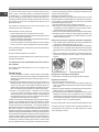
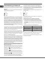
Adapting to different types of gas
To adapt the hob to a different type of gas other than
default type (indicated on the rating plate at the base of the
hob or on the packaging), the burner nozzles should be
replaced as follows:
1. Remove the hob grids and slide the burners off their
seats.
2. Unscrew the nozzles using a 7 mm socket spanner (fig.6), and replace
them with nozzles for the new type of gas (see table 1 “Burner and nozzle
characteristics”).
3. Reassemble the parts following the above procedure in the reverse order.
4. Once this procedure is finished, replace the old rating sticker with one
indicating the new type of gas used. Sticker are available from any of
our Service Centres.
Replacing the nozzles on separate “double ame “ burners
1. remove the grids and slide the burners from their housings. The burner
consists of 2 separate parts (see gure);
2. unscrew the burers with a 7 mm wrench spanner. The internal burner
has a nozzle, the external burner has two (of the same size). Replace
the nozzle with models suited to the new type of gas (see table 1).
3. replace all the components by repeating the steps in reverse order.
Adjusting the burners’ primary air
Does not require adjusting.
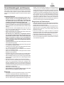
Setting the burners to minimum:
1. Turn the tap to the low ame position.
2. Remove the knob (g.7)and adjust the adjustment screw, which is positioned
in or next to the tap pin, until the ame is small but steady.
3. Having adjusted the ame to the required low setting, while the burner is
alight, quickly change the position of the knob from minimum to maximum
and vice versa several times, checking that the ame does not go out.
4. Some appliances have a safety device (thermocouple) tted. If the device
fails to work when the burners are set to the low ame setting, increase
this low ame setting using the adjusting screw.
5. Once the adjustment has been made, replace the seals on the by-passes
using sealing wax or a similar substance.
! If the appliance is connected to liquid gas, the regulation screw must be
fastened as tightly as possible.
! Once this procedure is nished, replace the old rating sticker with one
indicating the new type of gas used. Stickers are available from any of our
Service Centres.
! Should the gas pressure used be different (or vary slightly) from the
recommended pressure, a suitable pressure regulator must be tted to the
inlet pipe (in order to comply with current national regulations).

GB
21
Electrical
connections
DATA PLATE
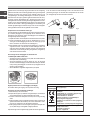
This appliance conforms to the following
European Economic Community directives:
- 2006/95/EC dated 12/12/06 (Low Voltage)
and subsequent amendments
- 2004/108/EC dated 15/12/04
(Electromagnetic Compatibility) and
subsequent amendments
- 93/68/EEC dated 22/07/93 and subsequent
amendments.
- 2012/19/EU and subsequent amendments.
EU Regulation no. 66/2014 implementing
Directive 2009/125/EC.
standard EN 60350-2
standard EN 30-2-1
ECODESIGN
Voltage 220-240V~ 50/60 Hz (see data plate)
Fig.5
A
Fig.6
Fig.7
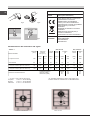
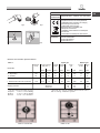
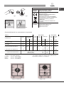
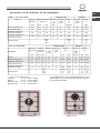
Burner and nozzle specifications
! The hob can only be installed above built-in ovens
with a cooling ventilation system.
* At 15°C and 1013 mbar- dry gas
Propane P.C.S. = 50.37 MJ/Kg
Butane P.C.S. = 49.47 MJ/Kg
Natural P.C.S. = 37.78 MJ/m
3
sag larutaNsag diuqiL1 elbaT
BURNER
Diameter
(mm)
Thermal power
kW (H.s.*)
By-pass
1/100
(mm)
Injector
1/100
(mm)
Flow *
g/h
Injector
1/100
(mm)
Flow*
l/h
Nomin. Reduc. G30G31 G20
90342123263219753.152.3031gniR elpirT .D
5917173705034.000.155yrailixuA .A
I. Double flame DC DR (internal) 30 0.90 0.4304465647086
I. Double Flame DC DR (external) 1304.101.3 57 70 298293 110390
Supply pressure
Nominal
Minimum
Maximum
28-30
20
35
37
25
45
20
17
25
PMG 41 DCDR SF PMG 42 SF
II
II
I
DD
DD
D
AA
AA
A

22
GB
Start-up and use
! The position of the corresponding gas burner is shown on every knob.
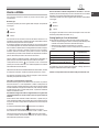
Gas burners
Each burner can be adjusted to one of the following settings using the
corresponding control knob:
0 Off
Maximum
Minimum
To light one of the burners, hold a lit match or lighter near the burner and, at
the same time, press down and turn the corresponding knob anti-clockwise
to the maximum setting.Since the burner is tted with a safety device, the
knob should be pressed for approximately 2-3 seconds to allow the automatic
device keeping the ame alight to heat up.
When using models with an ignition button, light the desired burner pressing
down the corresponding knob as far as possible and turning it anticlockwise
towards the maximum setting.
! Some models have a Double Flame burner. In this case, to activate it, simply
start by turning the knob so that it is aligned with the symbol , then press
it all the way in and hold it in this position for approximately 6 seconds, until
the automatic device keeping the ame alight has heated up.
! If a ame is accidentally extinguished, turn off the control knob and wait for
at least 1 minute before trying to relight it.
To switch off the burner, turn the knob in a clockwise direction until it stops
(when reaches the “●”/“○” position).
The “separate double ame” burner*
This burner consists of two concentric burners which can operate either
together or separately.
Use of the double ame on the maximum setting gives a very high power
which reduces cooking times with respect to conventional burners.
Moreover the double ame crown provides a more uniform distribution of heat
on the bottom of the pan, when using both burners on minimum.
To ensure that the double-ame burner is used to its full potential,
never set the inside ring to minimum and the outside ring to maximum
at the same time.
Pots and pans of all sizes can be used. In the case of the smaller pots and
pans we recommend the use of only the internal burner.
There is a separate control knob for each of the “separate double ame”
burners.
The knob marked by the symbol operates the external burner;
The knob marked by the symbol operates the internal burner.
To turn on one of the rings, press the relative knob in all the way and turn it
anti-clockwise to the high setting .
The burner is tted with an electronic igniter that automatically starts when
the knob is pressed in.
Since the burner is equipped with a safety device, after lighting the burner
keep the knob pressed in for about 2-3 seconds to allow the device which
keeps the ame lit automatically to heat up.
The selected burner can be regulated using the corresponding knob, as
follows:
0 Off
Maximum
Minimum
To switch off the burner, turn the knob in a clockwise direction until it stops
(when reaches the “●”/“○” position).
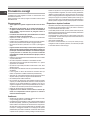
Practical advice on using the burners
To ensure the burners operate efciently:
• Use appropriate cookware for each burner (see table) so that the ames
do not extend beyond the bottom of the cookware.
• Always use cookware with a at base and a cover.
• When the contents of the pan reach boiling point, turn the knob to minimum.
Ø Cookware Diameter (cm)
6 - 14
24 - 26
10 - 14
26 - 28
Burner
A. Auxiliary
D. Triple Ring
I. Double Flame DC DR (internal)
I. Double Flame DC DR (external)
To identify the type of burner, refer to the designs in the section entitled, “Burner
and Nozzle Specications”.
! Make sure the pans do not overlap the edges of the hob while it is being used..
Precautions and tips
! This appliance has been designed and manufactured in compliance with
international safety standards. The following warnings are provided for safety
reasons and must be read carefully.
General safety
• This is a class 3 built-in appliance.
• Gas appliances require regular air exchange to maintain efcient
operation. When installing the hob, follow the instructions provided
in the paragraph on “Positioning” the appliance.
• These instructions are only valid for the countries whose symbols
appear in the manual and on the serial number plate.
• The appliance was designed for domestic use inside the home and is
not intended for commercial or industrial use.
• The appliance must not be installed outdoors, even in covered areas. It is
extremely dangerous to leave the appliance exposed to rain and storms.
• Do not touch the appliance with bare feet or with wet or damp hands and
feet.
• The appliance must be used by adults only for the preparation of food,
in accordance with the instructions outlined in this booklet. Any other
use of the appliance (e.g. for heating the room) constitutes improper
use and is dangerous. The manufacturer may not be held liable for
any damage resulting from improper, incorrect and unreasonable
use of the appliance.
• Ensure that the power supply cables of other electrical appliances do not
come into contact with the hot parts of the oven.
• The openings used for ventilation and dispersion of heat must never be
covered.
• Always make sure the knobs are in the “●”/“○” position when the appliance
is not in use.
• When unplugging the appliance always pull the plug from the mains socket,

GB
23
do not pull on the cable.
• Never carry out any cleaning or maintenance work without having detached
the plug from the mains.
• In case of malfunction, under no circumstances should you attempt to repair
the appliance yourself. Repairs carried out by inexperienced persons may
cause injury or further malfunctioning of the appliance. Contact a Service
Centre (see Assistance).
• Always make sure that pan handles are turned towards the centre of the
hob in order to avoid accidental burns.
• Do not use unstable or deformed pans.
• The appliance should not be operated by people (including children)
with reduced physical, sensory or mental capacities, by inexperienced
individuals or by anyone who is not familiar with the product. These
individuals should, at the very least, be supervised by someone who
assumes responsibility for their safety or receive preliminary instructions
relating to the operation of the appliance.
• Do not let children play with the appliance.
• The appliance is not intended to be operated by means of an external
timer or separate remote-control system.
Disposal
• When disposing of packaging material: observe local legislation so that
the packaging may be reused.
• The European Directive 2012/19/EU on Waste Electrical and Electronic
Equipment (WEEE), requires that old household electrical appliances must
not be disposed of in the normal unsorted municipal waste stream. Old
appliances must be collected separately in order to optimise the recovery
and recycling of the materials they contain and reduce the impact on human
health and the environment. The crossed out “wheeled bin” symbol on
the product reminds you of your obligation, that when you dispose of the
appliance it must be separately collected.
Consumers may take their old appliance to public waste collection areas,
other communal collection areas, or if national legislation allows return it
to a retailer when purchasing a similar new product.
All major household appliance manufacturers are active in the creation of
systems to manage the collection and disposal of old appliances.
Respecting and conserving the environment
• Make the most of your hot plate’s residual heat by switching off cast iron hot
plates 10 minutes before the end of your cooking time and glass ceramic
hot plates 5 minutes before the end of cooking time.
• The base of your pot or pan should cover the hot plate. If it is smaller,
precious energy will be wasted and pots that boil over leave encrusted
remains that can be difcult to remove.
• Cook your food in closed pots or pans with well-tting lids and use as little
water as possible. Cooking with the lid off will greatly increase energy
consumption.
• Use purely at pots and pans.
• If you are cooking something that takes a long time, it’s worth using a
pressure cooker, which is twice as fast and saves a third of the energy.
Maintenance and care
Switching the appliance off
Disconnect your appliance from the electricity supply before carrying out
any work on it.
Cleaning the appliance
! Do not use abrasive or corrosive detergents such as stain removers, anti-rust
products, powder detergents or sponges with abrasive surfaces: these may
scratch the surface beyond repair.
! Never use steam cleaners or pressure cleaners on the appliance.
• It is usually enough to wash the hob with a damp sponge and dry it with
absorbent kitchen roll.
• The removable parts of the burners should be washed frequently with warm
water and soap and any burnt-on substances removed. The burner caps
should NOT be put in the dishwasher to prevent dulling of the aluminum
part
• For hobs which ligth automatically, the terminal part of the electronic instant
lighting devices should be cleaned frequently and the gas outlet holes
should be checked for blockages.
• Before using the hob, the surface must be cleaned, using a damp cloth
to remove dust or food residues. The hob surface should be cleaned
regularly with a soultion of warm water and a non-abrasive detergent.
• For hobs which ligth automatically, the terminal part of the electronic instant
lighting devices should be cleaned frequently and the gas outlet holes
should be checked for blockages.
• Stainless steel can be marked by hard water that has been left on the
surface for a long time, or by aggressive detergents containing phosphorus.
After cleaning, rinse and dry any remaining drops of water.
Gas tap maintenance
Over time, the taps may become jammed or difcult to turn. If this happens,
the tap must be replaced.
! This procedure must be performed by a qualied technician authorised
by the manufacturer.
Troubleshooting
It may happen that the appliance does not function properly or at all. Before
calling the service centre for assistance, check if anything can be done. First,
check to see that there are no interruptions in the gas and electrical supplies,
and, in particular, that the gas valves for the mains are open.
The burner does not light or the ame is not even around the burner.
Check whether:
• The gas holes on the burner are clogged.
• All the movable parts that make up the burner are mounted correctly.
• There are draughts near the appliance.
The ame dies in models with a safety device.
Check to make sure that:
• You pressed the knob all the way in.
• You keep the knob pressed in long enough to activate the safety device.
• The gas holes are not blocked in the area corresponding to the safety
device.
The burner does not remain lit when set to minimum.
Check to make sure that:
• The gas holes are not blocked.
• There are no draughts near the appliance.
• The minimum setting has been adjusted properly.
The cookware is unstable.
Check to make sure that:
• The bottom of the cookware is perfectly at.
• The cookware is positioned correctly at the centre of the burner.
• The pan support grids have been positioned correctly.
Page is loading ...
Page is loading ...
Page is loading ...
Page is loading ...
Page is loading ...
Page is loading ...
Page is loading ...
Page is loading ...
Page is loading ...
Page is loading ...
Page is loading ...
Page is loading ...
Page is loading ...
Page is loading ...
Page is loading ...
Page is loading ...
Page is loading ...
Page is loading ...
Page is loading ...
Page is loading ...
Page is loading ...
Page is loading ...
Page is loading ...
Page is loading ...
Page is loading ...
Page is loading ...
Page is loading ...
Page is loading ...
Page is loading ...
Page is loading ...
Page is loading ...
Page is loading ...

56
NL
BE
Indesit Company S.p.A.
V
iale Aristide Merloni,47
60044 Fabriano (AN)
www.scholtes.com
195127851.00
10/2014 - XEROX FABRIANO
-
 1
1
-
 2
2
-
 3
3
-
 4
4
-
 5
5
-
 6
6
-
 7
7
-
 8
8
-
 9
9
-
 10
10
-
 11
11
-
 12
12
-
 13
13
-
 14
14
-
 15
15
-
 16
16
-
 17
17
-
 18
18
-
 19
19
-
 20
20
-
 21
21
-
 22
22
-
 23
23
-
 24
24
-
 25
25
-
 26
26
-
 27
27
-
 28
28
-
 29
29
-
 30
30
-
 31
31
-
 32
32
-
 33
33
-
 34
34
-
 35
35
-
 36
36
-
 37
37
-
 38
38
-
 39
39
-
 40
40
-
 41
41
-
 42
42
-
 43
43
-
 44
44
-
 45
45
-
 46
46
-
 47
47
-
 48
48
-
 49
49
-
 50
50
-
 51
51
-
 52
52
-
 53
53
-
 54
54
-
 55
55
-
 56
56


Ask a question and I''ll find the answer in the document
Finding information in a document is now easier with AI
in other languages
- italiano: Scholtes PMG 41 DCDR SF Guida utente
- français: Scholtes PMG 41 DCDR SF Mode d'emploi
- español: Scholtes PMG 41 DCDR SF Guía del usuario
Related papers
-
Scholtes PMG 41 DCDR SF Owner's manual
-
Scholtes PPF 30TC 120 Owner's manual
-
Scholtes PP Q40 TC SF User guide
-
-
-
-
Scholtes PPF 73 G User guide
-
-
-
Whirlpool PP 73 G Owner's manual
Other documents
-
Indesit BV 40/CS F User guide
-
Whirlpool PP 40 TC F User guide
-
Indesit PZ 750 R GH/HA User guide
-
-
-
Whirlpool PC 750 T (AN) R /HA User guide
-
Hotpoint PKL 641 IX/HA Owner's manual
-
Whirlpool PH 960MST GH/HA User guide
-
-
HOTPOINT/ARISTON PC 750 T (OS) R /HA User guide