Craftsman 351.217450 Owner's manual

Category
Power planers
Type
Owner's manual

This manual is also suitable for

Operator's Manual
CRRFTSMRN°I
5"
PLANER/MOLDER WITH DUST COLLECTION
Model No.
351.217450
Updated
CAUTION: Read and follow all Safety Rules and Operating Instructions
before First Use of this Product.
Sears, Roebuck and Co., Hoffman Estates, IL 60179 U.S.A.
wv,_N.sears.co nllcnsftsman
20382.03 Draft (12/23/2003)
Warranty.................................... 2
Safety Rules ............................... 2-3
Unpacking .................................. 3
Assembly ................................. 3-5
Installation................................. 5-6
Operation ................................ 6-14
Maintenance ............................. 15-16
Troubleshooting........................... 17-18
Parts Illustrationand List ................... 19-26
EspaSol................................. 26-43
FU LL ONE YEAR WARRANTY
If this productfailsdue to a defect in material or work-
manship withinone year from the date of purchase,
Sears will at its option repair or replace itfree of
charge. Contact your nearest Sears Service Center
(1-800-4-MY-HOME) to arrange for productrepair,or
returnthis productto place of purchasefor replacement.
If this productis used for commercial or rental purpos-
es, this warranty will applyfor 90 days from the date of
purchase.
This warranty applies only while this productis used in
the United States.
This warrantygives you specificlegal rights and you may
also haveother rightswhichvary from state to state.
Sears, Roebuck and Co., Dept. 8t7WA, Hoffman
Estates, IL 60179
WARNING: Foryour own safety, read all of the rules
and precautions before operating tool.
CAUTION: Always follow properoperating procedures
as defined in this manual even ifyou are familiarwith
use ofthis or similar tools. Remember that being care-
lessfor even a fractionof a second can resultin severe
personal injury.
BE PREPARED FOR JOB
Wear proper apparel. Do not wear loose clothing,
gloves, neckties,rings, braceletsor otherjewelry
which may get caught in movingparts of machine.
Wear protective hair coveringto contain long hair.
Wear safety shoes with non-slip soles.
Wear safety glasses complying with United States
ANSI Z87.1. Everyday glasses have onlyimpact
resistantlenses.They are NOT safety glasses.
Wear face mask or dust mask ifoperation is dusty.
Be alert and think clearly.Never operate power tools
when tired, intoxicatedor when taking medications
that cause drowsiness.
O Seam, Roebuck and Co.
2
PREPARE WORK AREA FOR JOB
Keep work area clean.Clutteredwork areas invite
accidents. -, -.
Do not use power tools in dangerous environments.
Do not use power tools in damp or wet locations. Do
not expose power tools to rain.
Work area should be proper{y lighted.
Proper electrical receptacle shouldbe available for
tool.Three prong plug should be pluggeddirectly
intoproperly grounded, thrae-prongreceptacle.
Extension cordsshouldhave a groundingprong and
the three wires ofthe extensioncordshouldbe of
the correct gauge.
Keep visitors at a safe distance from work area.
Keepchildren outofworkptace.Makeworl_shop child-
proof. Use padlocks, master switchesor remove switch
keysto prevent anyunintentional use ofpower tools.
TOOL SHOULD BE MAINTAINED i
Always unplugtool priorto inspection.
Consultmanualfor specificmaintainingand adjust-
ingprocedures. :
Keep tool lubricatedand clean for safestoperation.
Remove adjustingtools. Form habitof checking to
see that adjustingtools are removedbef(_raswitch-
ing machineon.
Keep all parts inworkingorder.Check to determine
that the guard or other parts willoperate i)ropedy
and performtheir intendedfunction. ,
Checkfor damaged pads, Check for aiignmentof
movingparts, binding,breakage, mountingand any
otherconditionthat may affect a tool'soperation.
A guard or other part that is damaged shouldbe
properlyrepairedor replaced. Do not perform
makeshiftrepairs.(Use parts listprovidedto order
replacement pads.)
KNOW HOW TO USE TOOL
Use dght toolforjob. Do not forcetool or attachment
to do a jobfor which itwas not designed.
Disconnecttoolwhen changing blades. ,
Avoidaccidental stad-up, Make surethatlthe switch
is in the OFF positionbeforepluggingin. _
Do not force tool.It willwork mostefficientlyat the
ratafor whichit was designed,
Keep handsaway from movingpartsand Cutting
surfaces. :'
Never leave tool runningunattended.Turnthe power
offand do not leave tool untilitcomes to a complete
stop.
Do not overreach.Keep properfooting and balance.
Never standon tool.Seriousinjurycould occurif toolis
tippedor if blade isunintentionallycontacted.
Knowyourtool. Learn the tool'soperation,applica-
tionand speciticlimitations.... :_,_
Use recommendedaccessodes (refe=:topage 25).
Use of improperacoessodesmay cause risk of
injuryto persons. : -*L_
Handle workpiece correctly.Protect handsfrom
possibleinjury.
Turn machine off if itjams. Bladejams when it digs
too deeply intoworkpiece. (Motor force keeps it
stuck in the work.)
Always keep drive, cutterhead and blade guards in
place and in proper operating condition.
Feed work into blade or cutter againstdirectionof
rotation.
CAUTION: Think safety! Safety isa combination of
operator common sense and alertness at alltimes
when tool is being used.
WARNING: Do not attemptto operate tool untilit is
completely assembled accordingto the instructions.
Refer to Figures 1 and 2.
Check for shippingdamage. If damage has occurred,a
claim must be filedwith carder. Check for complete-
ness. Immediately report missingparts to dealer.
The planer/molder comes assembledas one unit.
Additional parts which need to be fastened to
planer/molder shouldbe locatedand accounted for
beforeassembling.
A. Handle Assembly
B. 5-0.8 x 25mm Socket Head Bolt
C. Plug
D. Roller Height AdjustmentWrench
E. Dust Chute
F. 6-1.0 x 25mm Socket Pan Head Screw
G. Roller (2)
H. Molding Gib and Spacer Set (4)
Not Shown:
Half Bag Dust Collection Set
Auxiliary Table Hardware Bag (Part No. 21012.00)
includes:
#10-32 x 23/d' Socket Head Bolt(2)
#10 FlatWasher (2)
Clamp (2)
1/,-20x 11/," Wing Screw (4)
1/4"Flat Washer (4)
Table Insert (4)
Figure1 - UnpackingPlaner/Molder
The stand comes unassemb_edand packed along with
the planer/molderin the same box.Locate and identify
all parts beforeattemptingassembly.
A. Frame, long (2)
B. Frame, short (2)
C. Brace, long (2)
D. Brace, short(2)
E. Leg, stamped 'A' (2)
F. Leg, plain (2)
Not Shown:
Stand Hardware Bag (20896.00) includes:
8-1.25 x 80ram Hex Head Bolt(4)
8mm Flat Washer (8)
8-1.25mm Hex Nut (4)
S/le-18 X =/4" Carriage Bolt(24)
51_e"-18Washer Head Bolt(24)
A
E
F
Figure 2 - Unpacking Stand
WARNING: Do not attemptassembly ifparts are miss-
ing. Use this manual to order replacement parts.
ASSEMBLE STAND
Refer to Figures3 and 4, Page 4.
Place the long and shortframe pieces on the floor.
Layout the pieces in a rectanglewiththe long and
shortframes oppositeto each other. '
Assemble the legs to the outsideof the frames using
cardage boltsand nuts.
NOTE: Leg set that isstamped 'A' goes in diagonally
opposingcorners and the plainset goes'inother two
corners. Leg 'A'must be installedwith short brace on
rightand long brace on left in order for the stand to be
square and level(See Figure4, Page 4).
Leave nuts and bolts finger tightfor now.
3
Figure3 - AssembleLegsto Frame
Attach the long and short braces to the legs.
Set stand upright on floor and tighten all boltsand
nuts firmly.
Figure5 - InstallingHandle
INSTALL DUST CHUTE
Refer to Figure 6,
Slide dust chute over fan housing. Secure in position
with screw.
Attach the Half Beg Dust Collection Set (included)
only after mounting planer/molder to stand.
Figure4 - Assembled Stand
INSTALL HANDLE
Refer to Figure 5.
Handle with knob is installedon the top rightof the
planer/molder.
Insert handle with knobonto elevationscrewtop.
Secure handle with sockethead boltusingwrench
provided,
Insert plug into handle to ooverbolt.
4
Figure 6 - Installing Dust Chute
MOUNT PLANERJMOLDER TO STAND
Refer to Figure 7, page 5.
Planer/molderis designedto be portable so itcan be
movedtojob site, but shouldbe mountedto its
includedstand for stability.
Make sure stand is located on a firm, level surface in
a place with ample lightingand correctpowersupply.
Make sure there is plentyof roomfor movingthe
workpiece throughthe entire cut.There must be
enoughroomthat neither the operatorsor the
bystanderswill have to stand in linewith the wood
whileusingthe tool.
Place the planer/molderon stand top.
CAUTION: Planer/molder weighs approximately150
Ibs.Two people may be required to liftplaner/molder.
Figure 7 - Mounting Planer to Stand
Position the planedmolder on stand top as shownin
Figure 7. Make sure that the four holes on the plan-
edmolder base casting are aligned with four slots on
standtop.
Planer/molder is supplied with mounting hardware.
Insert e 8-1.25 x 80mm he)( head bolt with 8mm fiat
washer into each of the four mounting holes on the
base casting. Fasten bolts with an 8mm fiat washer
and hex nut from underneath the stand top.
Tighten ell four bolts and make sure planer/molder is
securely mounted on stand.
INSTALL THE HALF BAG DUST
COLLECTION SET
Refer to Figure 8.
The Craftsman Half Bag Dust ConectionSet is
designedto providedust collectionfor woodworking
toolswith a 21/2"diameter dust exhaust port.The filter
bag attaches to a 30-gallon trash can or a 30-gallon x
1.3 milplastictrash bag for easy, convenientsawdust
disposal(trash can and plastictrash bag not included).
Mount planer/molder to stand beforeinstallingDust
CollectionSet.
Spring
__ DustChute
Support
Filter
J'_- nne r Segments
/' co. /
/s,.port
Figure8 - Half Ba, Dust CollectionSet
To use dust collection set with a trash can:
Place springinsidefilter bag arm.
Slide arm with spring over dust chute,
Place band of the bag over rim of trash can and
secure bag by tightening strap.
To use dust collection set with a trash bag:
Place spring inside filter bag arm.
Slide arm with spring over dust chute.
Assemble bag support. Slide connectors into
channels of support segments.
Slide plastic trash bag inside and over bag support.
Let bag overlap 3-4".
Place band of the filter bag over and into the
channel of the bag support.
Secure in positionbytighteningstrapl
INSTALL RETURN ROLLERS
Refer to Figure 36.
Insert return rollers(Key No. 11) intomiler bushings
(Key Nos. 1 and 2).
5
POWER SOURCE
WARNING: Do not connect planer/molderto the
powersource untilall assemblysteps have been com-
pleted.
The motoris designedfor operationon the voltageand
frequency specified.Normal loadswillbe handled safe-
lyon voltagesnot morethan 10% above or below spec-
ifiedvoltage. Runningtheuniton voltageswhichare not
withinrange may cause overheatingand motorbum out.
Heavy loads requirethatvoltageat motorterminals be
no less than the voltage specifiedon nameplate.
Power supply to the motoriscontrolledby a switch
with key.Removingthe key from switchwill lock the
unitand prevent unauthorizeduse.
GROUNDING INSTRUCTIONS
WARNING: Improper connection of equipment
groundingconductor can resultin the risk of electdcal
shock.Equipment mustbe groundedwh!le in use to
protectoperatorfrom electdcal shock. :
Check with a qualifiedelectricianifyou do not
understandgroundinginstructionsor if you are in
doubt as to whetherthe toolis prope,dygrounded.
This tool is equippedwith an approvedcord rated at
150V and a 3-pronggroundingtype plug (see Figure
9) for your protectionagainst shockh;_zards.
Groundingplug shouldbe pluggeddirectly intoa
properly installedand grounded3-prong grounding-
type receptacle, as shown(see Figur_ 9).
PropedyGroundedOutlet\ r_l
GroundingProng,,, Xx'l._ II
3 ProngPlug_O_j I]
Figureg - 3-ProngReceptacle
Do not removeor altergroundingpronginany manner.
Inthe eventofa malfunction or breakdown, grounding
providesa pathof leastresistanceforelectricalshock.
WARNING: Do not permitfingers to touchthe termi-
nals of plug when insertingor removingfrom outlet.
Plug must be plugged into matchingoutlet that is
properly installedand groundedin accordance with
all localcodes and ordinances.Do not modifyplug
provided.If it will not fit in outlet, have proper outlet
installed bya qualified electrician.
Inspect tool cordsperiodically,and if damaged, have
repaired byan authorized service facility.
Green (or green and yellow)conductorin cord isthe
groundingwire. If repair or replacement of the elec-
tric cord or plug is necessary,do not connect the
green (or green and yellow)wire to a live terminal.
A 2-prong wall receptacle mustbe replaced with a
properly grounded3-prong receptacle installedin
accordance with National Electric Code and local
codes and ordinances.
WARNING: Any receptacle replacement shouldbe
performed by a qualified electrician.
A temporary 3-prong to 2-pronggroundingadapter (see
Figure 10) is available for connecting plugs to a two
pole outlet if it isproperly grounded.
GroundingLug _ r==_MakoeSUrc_e'rhis
Adapter IIToAKnown
3-ProngP__.. Ground
"_"--'- _"_2-Prong Receptacle
Figure10 - 2-ProngReceptaclewith Adapter
Do not use a 3-prong to 2-prong groundingadapter
unless permitted by local and nationalcodes and
ordinances.(A 3-prong to 2-prong groundingadapter
is not permittedin Canada.)
Where a 3-prongto 2-preng groundingadapter is
permitted, the rigidgreen tab or terminal on the side
of the adapter mustbe securely connected to a
permanent electricalground such as a propedy
groundedwater pipe, a propedy groundedoutletbox
or a properlygroundedwire system.
Many cover plate screws, water pipes and outlet
boxes are not properlygrounded.To ensure proper
ground, groundingmeans mustbe tested bya quali-
fied electrician.
EXTENSION CORDS
The use of any extensioncord will cause some drop
in voltage and lossof power.
Wires of the extension cord mustbe of sufficientsize
to carry the currentand maintainadequate voltage.
The minimumextension cord wire size isA.W.G. 12.
Do not use extension cords over 25 feet long.
Use only 3-wire extensioncords having3-prong
groundingtype plugs and 3-pole receptacles which
accept the tool plug.
If the extensioncord isworn, cutor damaged in any
way, replaceit immediately.
Planeris suppliedwith a 3 HP motor installed.
The 120 Volt AC universalmotorhas the following
specifications:
Horsepower (Maximum Developed)............ 3 HP
Voltage................................... 120
Amperes............................ _...... 15
Hertz ..................................... 60
Phase.............................. _... Single
Cutterhead RPM ..................... : .... 5500
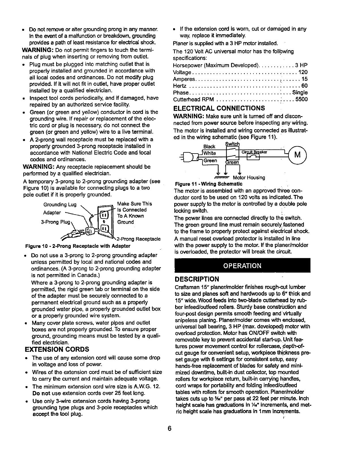
ELECTRICAL CONNECTIONS
WARNING: Make sure unitisturned off and discon-
nected from powersource beforeinspectinganywidng.
The motorisinstalledand wiringconnected as illustrat-
ed in thewiringschematic (see Figure 11).
Switch
Cir k_"
MotorHousing
Figure11- WiringSchematic
The motoris assembledwith an approvedthree con-
ductorcordto be used on 120 volts as indicated.The
power supplytothe motoris controlledby a double pole
locking switch. !.
The power linesare connecteddirectlyto the switch.
The green groundlinemust remainsecurel_fastened
to the frame to propedyprotectagainst electricalshock.
A manual resetovedoad protectoris installedin line
with the powersupplytothe motor.If the planer/molder
isoverloaded,the protectorwill break the circuit.
DESCRIPTION
Craftsman15" planer/molderfinishesrough-cutlumber
to size and planessoftand hardwoodsup to 6" thickand
15"wide.Woodfeeds intotwo-blade cutterheadbyrub-
ber infead/outfeedrollers.Sturdybase censtmcUon and
four-post designpermitssmoothfeeding andvirtually
snipelessplaning.Planer/moldercomeswithenclosed,
universalballbeadng,3 HP (max.developed)motorwith
ovedoad protection.Motorhas ON/OFF switchwith
removablekeyto preventaccidentalstart-up.Unitfea-
tures power movementcontrolfor rollercase,depth-of-
cut gaugefor convenient setup,workpiecethid(ness pre-
set gaugewith6 settingsfor consistentsetup,easy
hands-flea replacementof bladesfor safetyand mini-
mizeddowntime,built-indust collector, top mounted
rollersfor workpiecareturn, built-incarryinghandles,
cordwraps forportability and folding infeed/outfeed
tables with rollersfor smoothoperation.Planer/molder
takes cutsupto =A_"per pass at 22 feet per minute.Inch
heightscale hasgraduationsin 'A,"increments,and met-
dcheightscalehas graduationsin lmm Incrslments.
6
Table Size ............................. 15 x 16"
ExtensionTable Size .................... 15 x 11"
Base Size ............................. 32 x16"
WorkpieceWidth (max.) ...................... 15"
WorkpieceThickness (max.) ................... 6"
Maximum Depth of Cut ..................... 3/32"
Cuts Per Minute ......................... 11,000
Feed Rate........................... 11122FPM
Overall Dimensions .......... 56" H x 34" W x 40" D
Weight ................................ 150 Ibs
OPERATION SAFETY RULES
WARNING: For yourown safety,road all of the
instructionsand precautions beforeoperating tool.
WARNING: Operation of any powertoolcan result in
foreignobjects being thrown intoeyes whichcan result
in severe eye damage. Always wear safety goggles
complyingwith United States ANSI Z87.1 (shown on
package) beforecommencing powertool operation.
CAUTION: Always observe the following safety pre-
cautions:
Know general power toolsafety.Make sure all pre-
cautions are understood(see pages 2, 3 and 7).
Whenever adjustingor replacingany partson
planer/molder,turn switchOFF and removeplugfrom
power source.
Make sure all guards are properlyattached and
securely fastened.
Make sure all movingparts arefree from interference.
Always wear eye protectionor face shield.
Make sure blades are aligned and properlyattached
to cutterhead.
Do not plug in planer/molder unlessswitchis in off
position. After turning switchon, allow planer/molder
to come to fullspeed beforeoperating.
Keep hands clear of all movingparts.
Do notforce cut. Slowingor stallingwilloverheat
motor.Allow automaticfeed tofunction properly.
Use quality lumber.Blades last longerand cutsare
smoother with good qualitywood.
Do not plane material shorter than 17", narrower
than ¾", wider than 15"or thinner than t/8".
Never make planing cut deeper than =/_".
Maintain the proper relationshipsof infeedand out-
feed table surfaces and cutterhead blade path.
Do not back the work towardthe infeedtable.
Takeprecautionsagainstkickback.Do not permitany-
one to stand or cross in lineofcutterhead'srotation.
Kickbackor thrown debds willtravelin thisdirection.
Turn switchoffand disconnectpowerwhenever plan-
er/molder is notin use.
Replace blades as they become damaged or dull.
Keep planer/molder maintained.Followmaintenance
instructions(see pages 16-16).
OPERATING CONTROLS
ON/OFF SWITCH
Refer to Figure 12.
The ON/OFF switch islocated on the front of the plan-
er/molder motor.To turn the planar/molderON, move
the switch to the up position. To turnthe planer/molder
OFF, move the switch to the down position.
CIRCUIT BREAKER
Refer to Figure 12.
The planer/molderisequipped with a motorprotection
device-circuitbreaker.The breakerwill automatically
shut the planer/molderoff when excessivecurrent is
consumed.
If the breaker istripped, turn the planer/molderoff and
resetthe circuitbypressingthe button.
CAUTION: Be sure to turnthe planer/molderoff prior
to resettingthe circuitbreakerto avoid unintentional
start-upof the planer/molder.
Figure 12 - ONIOFF Switch; Circuit Breaker On Right
SWITCH LOCK
Refer to Figure 13.
The planer/molder can be lockedfrom unauthorized
use by lockingthe switch.To lockthe switch:
Turn the switch to OFF positionand disconnectplan-
er/molder from power source.
Pull the key out.The switchcannotbe turned on with
the key removed.
NOTE: Should the key be removedfrom the switch at
the ON position,the switchcan be turned off but cannot
be turned on.
To replace key,slide key intothe sloton switch until
itsnaps.
For precise movement, rotate handle with knob.One
complete rotationof handle willraise or lower renercase
by 1/16"(see Figure 15).
A rotationaldirectionlabelwith depth indicatorislocat-
ed under the handle.
Figure 13 - Removing Locklng Key
RAISING AND LOWERING ROLLERCASE
Refer to Figures 14 end 15.
The rollercasecontains the motor,cutterhead and dust
collector.The depth-of-cut is controlled by raisingor
loweringthe rollercase. For rapid movementof the
rollercase, pushup or down on powerelevation lever
while motor is running(see Figure 14).
WARNING: Do notattempt to engage powerelevation
while planing.Keep hands clear of knobon top of
planer/molder.
Figure 14 - Power Elevation and Feedrate Controls
Figure 15 - Manually Raising or Lowering the Rollercase
FEED RATE ADJUSTMENT
Refer to Figure 14.
The planer/molder has a 2-speed gearbox that feeds
the workpiece at 22 feet per minute(standard plan-
ing) and at 11 feet per minute(for moldingor finish
planing).
Finish planinga workpiece resultsin a better surface
finish than that obtained byplaning at the higher
speed.
The knobfor adjustingthe feed rate is locatedon the
left side of the top ofthe mllercese.
NOTE: Only change feed rate while the machine is
running.
DEPTH-OF-CUT GAUGE AND SCALE
Refer to Figure 16, page 9.
A depth-of-cutgauge is attached to the frontof the
rellercase.The pointeron the depth-of-cutgauge accu-
ratelydisplays the depth-of-cutper passwhen work-
piece is positionedbelowthe gauge. Crankingthe han-
dle moves the mllercase down and the pointershows
depth-of-cutup to 3h=".
Recommended Maximum Depth-Of-Cut:
Hard/Softwood up to 8" wide:.................. 3/_,,
Hard/Softwood 8" to 15" wide: ................... 1/_,,,
The English/Metricscale with pointerallowseasy
adjustment of rollercase height.This scale indicates
the finishedsize ofthe workpiece.
8
Figure16 - Depthof Cut Gauge and Scale
WORKPIECE THICKNESS PRESET GAUGE
Refer to Figure 17.
A sixpositionworkpiecethicknesspre-setcontrolknobis
mountedon the rightsideof the planer/molder.This fea-
tureallowsquick productionof identically sizedwork-
pieces.Six settingsare provided:lk", lk", _h",3k",1" and
1tk,,.
Example: Ptene a 2" thick workpiece downto 1V4".
Raise or lowerrollercese until itisjust above the
workpiece.
Positionthe workpiece on the planer/moldertable
belowthe rollercese.
Rotate knob until 1V,"is indicated.
The planer/molder is now set to stop the rellercase
when the workpiece thicknessreaches 1W'.
NOTE: To reset for a differentdepth stop,gently raise
the rellercese by about 2 rotations.Turnknob to desired
setup.
Figure 17 - Setting Preset Depth Control Knob
111 1B /
Planing Molding InitialMoldingCut
Figure 18 - Feed Roller Height Adjustment
For planing, use setting I.
For molding, use Setting II.
For the first molding cut, use Setting III.
The feed roller height setting is indicated by the mark-
ing that is facing upward on the rollerheight adjustment
shaft.
FEED ROLLER HEIGHT ADJUSTMENT
Refer to Figures 18 and 19.
Craftsman 15" planedmolder has three height settings
for the feed rollers.The provided angled wrench isused
to adjust rollerheight.Tilt wrenchhead to clear the
infeed table edge.
Figure 19 - Adjusting the Feed Roller Height
ANTI-KICKBACK PAWLS
The planer/molder issuppliedwith anti-kickbackpawls
that help preventthe cutterheadfrom kickingback the
workpiece.
CAUTION: Never stand infront of infeedor outfeed
side of planer/molder.Alwaysstand to o_e side of plan-
er/molder to avoid injuryif a kickbackofthe workpiece
shouldoccur.
PREPARE WORK
Thickness planer/molderworks bestwhen lumber
has at least one fiat surface.
Use surface planer/molderor jointerto create a fiat
surface.
9
Twisted or severely warped boards canjam
planer/molder.Rip lumber in hall to reduce magni-
tude of warp.
Work shouldbe fed into planer/molderin same
directionas the grainof the wood. Sometimes grain
willchange directions in middle of board. In such
cases, if possible, cut board in middle before planing
so grain direction is correct.
CAUTION: Do not plane board which is less than 17"
long; force of cut could split board and cause kickback.
PLANING
WARNING: Always turn the planer/molderoff and
disconnectit from the power sourcewhenever blade
cover is removed. Never operate planer/molderwithout
the blade cover properly secured.
The planer/molderissuppliedwith planingbladesmount-
ed in the cutterheadandthe infeedand ouffeedrollers
adjustedto the correct height.The planer/molderiscapa-
ble ofworkingat twodifferentfeed rates.Feed rate refers
to rateat whichlumber travelsthrough planer/molder.
Planingcan bedone at 22 FPM (standardplaning)orat
11 FPM foran improvedsurfacefinish (see Feed Rate
Adjustment).
Positionrollercaseto producethe depth of cut
desired.
Operator isresponsiblefor aligningwork so it will
feed properly.
Lift edge to infeed side of the table by grasping
edges of board at approximatelymiddle of length.
Boards longerthan 24" shouldhave additionalsup-
port from free standingmaterial stands.
Positionthe workpiece with the face to be planed on
top.
Turn the planer/molderon.
Rest board end on in-feedtable and direct board into
planer/molder.
Gently slide the workpiece intothe infeed side of the
planer/molder untilthe infeed rollerbegins to
advance the workpiece.
Let go of the workpiece and allow automaticfeed to
advance the workpiece.
Do not push/pullon workpiece.
Move to the rear and receive planed lumber by
graspingit in same manner as itwas fed.
CAUTION: Do not stand directlyin line with frontor
rear of planer/molder.
Do not grasp any portionof board whichhas not
gone past out-feed roller.
Repeat this operation on all boards which need to be
same thickness.
Planer/molder has return milers on top so assistantcan
pass work back to operator (see Figure 20).
NOTE: Assistant mustfollow same precautionsas
operator.
Surface thatthe planer/molderproducesis smoother
if shallowerdepthof cut is used.
Figure 20 -Workplece on the Return Rollers
DEPTH OF CUT
Thickness planingrefers tothe sizingof lumberto a
desired thicknesswhile creating a level surface parallel
to the oppositeside of the beard. Boardthickness
which the planer/molderwill produceis indicatedbythe
scale, and depth-of-cut-gauge.Preset the planer/molder
to the desiredthicknessof finishedworkpiece using
knob.See "VVorkpieceThickness Pre-set Gauge", page
9.
Depth-of-cutis adjustedby raisingor loweringthe
rollercaseusing handle.
Qualityof thicknessplaningdepends on the opera-
tor'sjudgement aboutthe depth of cut.
Depthof cutdepends on the width, hardness,damp-
ness, grain directionand grain structureof thewood.
Maximumthicknessof wood which can be removed
inone pass is=,_"for planingoperations on work-
piece up to 8"wide.Workpieca mustbe positioned
awayfrom the center line ofthe table to cut3/=,,.
Maximumthicknessof wood whichcan be removed
in one pass is _A0"for planingoperationson work-
piece from 8"up to 15"wide.
Foroptimumplaning performance, the depth of cut
shouldbe lessthan ¼6".
Board shouldbe planed with shallowcuts untilthe
work has a levelside.Once a levelsurface has been
created, flipthe lumberand create parallel sides.
Plane alternatesidesuntilthe desiredthickness is
obtained.When halloftotal depthofcutistakenfrom
each side,the boardwillhavea uniformmoisturecon-
tentand additionaldryingwillnot causeittowarp.
Depthof cut shouldbe shallowerwhen work is wider.
When planinghardwood,take light cuts or plane the
wood in thin widths.
Make a test cut witha test piece and verifythe thick-
ness produced.
10
Check accuracy oftest cut priortoworkingon fin-
ishedproduct.
AVOID DAMAGE TO BLADES
Thickness planer/molder is a precision woodworking
machine and shouldbe used on qualitylumber only.
Do not plane dirtyboards;dirt and small stones are
abrasive and wear out blade.
Removenailsand staples.Use planer/molderto cut
woodonly.
Avoid knots.Heavily cross-grainedwood makes
knots hard. Knots can come loose and jam blade.
CAUTION: Any articlethat encountersplaner/molder
bladesmay be forciblyejectedfrom planer/moldercreat-
ingdsk of injury.
AVOIDING SNIPE
Snipe refersto e depression at either end of board
caused by an unevenforce on cutterhead when
work is enteringor leaving planer/molder.
Snipe occurswhen boards are not supported prop-
erly or when only one feed rollerisin contact with
work at beginningor end of cut.
To avoidsnipe on the lead edge of the workpiece,
adjustthe infeedtable up slightlyabove hodzontaL
To avoidsnipe on the trailingedge of the workpiece,
adjustthe ouffeed table up slightlyabove horizontal.
When planing more than one board ofthe same
thickness, butt boardstogether to avoidsnipe.
Snipe is more apparent when deeper cuts are taken.
Feed work in direction of grain.Work fed against
grain will have chipped, splintered edges.
MOLDING
Molding, also known as millworkor trim, can be defined
as a stripof wood milledwith a plain or decorativesur-
face which is continuousthroughoutitslength.
Toget superior moldingfinish,workpieca mustbe
planed and presized pdor to molding.Always presize
the workpieca to within ',_,"of the finalthickness
priorto molding.
During moldingoperation, do not exceed I/,, total
depth of cut.
Certain molding profilesrequireouter edge clean-up.
When using such profilesthe workpieca mustbe pre-
sized to t_,,larger than the finalwidth.This willallow '1,,"
for clean-up on either side.
Certain moldingprofilescut onlythe edge of workpieca.
When using such profilesworkpieca mustbe presized
to the same widthas the final width.
INSTALLING MOLDING CUTTERS
Refer to Figures21-24.
NOTE: When installingmoldingcuttersor pattamknives,
only use the gibssupplied with this planer/molder.
The moldingcutter bits,Sears Model Numbers 23301
through 23313, and Picture Frame Cutter Set 24023
are 'k" thickand are installedusing the moldinggibs
and lk" spacers providedwith the planer/molder.
The cutterhead on this planer/molderhas four slots.
Two slotsare used to hold the planing blades.The
other two slots are used to hold moldingcuttersand
pattern knives.The settingblockin the slot alignsthe
cuttersso that both cutterscut theworkpiece in the
same positionprovidingprecise cutsand improvedsur-
face finish.
Turn the planer/molderoff and unplugthe
planer/molderfrom the power source.
Loosen and removecenter screwfrom cover on the
rear side of planer/molder.Lif_cover.
Figure 21 - Remove Center Screw, Lift Cover to
Access Cutterhead
Carefully turn cutterheadby hand towards you until it
is stopped by the self-engaginglatch.
11
Figure 22 - Latch Located at Left End of Cutterhead
Ifthe slotfacing you containsthe blade, depress the
red latch at the left hand side of the cutterhead, and
carefully rotate it towardsuntilit stops at the slot with
setting block.
Be sure the slot is clean and free of any dirt, chips
or debris.
Slide molding cutter against edge of setting block,
place gib in slot,then place spacer at opposite end
of gib, and secure in position using the gib screws;
Tighten gib screws equally to produce equal pres-
sure on the cutter and spacer (see Figure 23).
Figure23 - MoldingCutterInstalled
NOTE: For each setup onlytwo molding cutters are
mounted on the cutterhead ofthis planer/molder.
Depress latch and rotate cutterhead 180=.
Repeat the same procedurefor mountingthe cutter
in the other cutterhead slot.
Operate the planer/molderfor five minutesand
check all gibscrews fortightness.
Make sure to recheckthe gib screws after every two
hoursof use.
NOTE: Make sure spacer is ofthe same thicknessas
the cutter, spacer islocated at oppositeend of gib and
that all gibscrews are secure.
Screw
Gib
Cutter
Figure 24 - Note Odentatlon of Screw and GIb with
Respect to Slot
INSTALLING THE PA'I-rERN KNIVES
Refer to Figure 25.
The steel patternknives, Sears Model Numbers 23331
through 23341, are '/,"thick.The patternknives ere
installedin the same manneras the molding cutters
except that the '/,"thick spacersare used.
NOTE: For each setup onlytwo pattern knivesare
mounted on the cutterheadof this planer/mo!der.
The planer/molderwillacoept multiple patternknives
or moldingcuttersetups.Figure25 showsthe topand
bottomknivesofthe tongueand grooveknifeset.
Gib
1/4"Thick
Spacer /
Groove
Pattern
Knife
Tongue
Pattern
Knife
Figure 25 - Multiple Setup, Tongue and Groove Knives
RELIEF KNIVES
Many of the ¼" pattern knivesare supplied with relief
knives,The reliefknives are used tocut a relief on the
backside of the moldingso that the moldingwill better
fit irregularsurfacessuch as plasteredwalls.
Always cut the relief first before molding the workpieca,
so that there is a fiat surface for the workpieca to slide
on during the molding operation. If the molding is done
first, the workpiece will not lie fiat on the feed table and
therefore the relief cannot be cut.
AUXILIARY TABLE
Refer to Figures26, 27 and 28, pages 13 and 14.
Some of the cuttingbitsand pattern knivesam designed
to cut all of the way through the workpiece and '/,e"
beyondthe workpieca.An auxiliarytable withguide
fences mustbe fabdcated to perform moldingIopera-
tions.
This produces a smoothedge and finalsizingofthe
workpiece.When usingthese bits or knives,an auxiliary
wood table mustbe mountedon the table to prevent
damage to the table and the bitsor knives.The
planer/molderis providedwithmountinghardwareto
accommodatean auxiliarytable.
The auxiliarytable shouldbe made from smoothparti-
cle board or plywoodto providea smooth surfacefor
the workpieceto slide on.
12
GUIDE FENCES
When molding,the workpiece mustbe guided intothe
molding cutter bits or knives properlyin order to pro-
duce the desired shape and size molding.Usingprop-
edy adjusted guide fences assures the workpiecepass-
es the molding cutters/knivesin the same position
using multiple passes. Figure 26 shows an auxiliary
table with guide fences mounted to the planer/molder
table.
Figure 26 - AuxlliaryTable with Guide Fences
The mounting boltpasses through the auxiliarytable
and fixed guide fence, through space between table
and extensiontable, and clamps to lipon the base.
Figure 27 - Auxiliary Table Clamp Attaches to Base
MOLDING OPERATION
Mount auxiliarytable withguide fences ontothe
table.
Install the required moldingcutter bits/knives in the
cutterhead.
Lower the rollercaseand insert the workpiecerela-
tiveto the positionof cutter bits/knivas.
Positionthe guide fencesrelativeto the positionof
the workpiece and bits/knives.
Lower the rollercaseuntilthe workpiecejust contacts
the infeedroller.
Record the height of the rollercaseas indicatedon
the scale.
Raise the rellercase and removeworkpiece.
Lower the rollercasebacktothe recordedmeasure-
ment. Continueto lowerthe rollercaseone fullturn
of the crank-handle.Recordthe measurement-- this
isthe first pass measurement.
Switch on the planer/molderand insertthe work-
piece untilthe feed rollerbegins toadvance the
workpiece.
NOTE: When usingcertain cutterbits/knives,the
workpiece may feed in a jerky motion.Ifthis hap-
pens, turnthe bandwheel and raise the table until
the workpiece advances smoothly.Revise the first
pass measurement with the current reading.
During moldingoperation,do not exceed I/," total
depth of cut.
If your moldingrequiresseveral passes, make sure
you runall yourstockbeforechangingthe setup for
each pass.This will assure conformity of shape
between workpieces.
Figure 28, page 14 shows dimensionsof the auxil-
iary table and guide fences.
13
110.Smm--
75,5mm
-43ram-- -- 6.Smm--
169.5mm
38tmm
340.5mm
305.5mm
270.5mm
I
-4
1
273mm,
Mounting
I
Mounting
Hole _r
Clamp Set
/
J
42 m_ 14.Smrn.
I
!
i
Ll;'im
3
Wing Screw
Flat Washer
Figure 28 - Dimensions for Auxiliary Table and Guide Fences
14
WARNING: Be sure planer/molder is unpluggedfrom
any power source and turned off before attempting any
maintenance.
CLEAN PLANER/MOLDER
Keep planer/molder clean of any wood chips, dust,
dirtor debris.
Clean the four steel columnsto preventthe relier-
case from bindingwhen raised and lowered.
Keep the anti-kickbackpawls clean and operating
smoothlyto preventinjurydue to kickback.
After each ten hours ofoperation, clean the
chain/gear drive mechanism.
Using a clean, dry cloth, clean all of the chainsand
gears ofwood chips, dust, and oldgrease.
LUBRICATION
The table surface can be coated with a lubricant,
such as furniture wax, to make the workpiece feed
smoother.Be sure that the lubricant used does not
affect the ability to finishthe workpiece with varnish,
sealer, etc.
For example, do not use any silicone base lubt_cents
because they will ruin any attempt to finishthe wood.
Use commonautomotive bearinggrease to lubricate
all chains and gears. Be sure all chains and gears
have plenty of grease.
Motor and cutterheed bearingsare sealed and need
no lubrication,
CHECK FORWORN BLADES
Condition of blades affects precisionof cut. Observe
quality of cut which planer/molderproducesto check
cendition of blades.
Dull blades tear, rather than sever wood fibersand
producefuzzy appearance.
Raised grain occurswhen dull blades poundon
woodthat has varying density.Raised edge will also
be producedwhere blades have been nicked.
REPLACE BLADES
Refer to Figures 29 through 32.
WARNING: Always turn planer/molderOFF and dis-
connect from power source beforestarting any mainte-
nance work.
NOTE: Always reverse or replace both bladesas a set.
Loosen and remove center screw from cover on the
rear side of planer/molder.Lift cover.
' +!!;S!_!
Figure 29 - Remove Center Screw, Lift Cover to
Access Cutterhead
Carefully turn cutterhead by hand towards you until it
is stopped by the serf-engaging latch.
Figure 30 - Latch Located at Left End of Cutterhead
Loosen all seven gib boltsenoughso that blade is
loose.
Figure 31 - Loosen All GIb Bolts
GentJylift old blades from the cutterhead usingthe
two magnets.Do not make contactwith the blade
usingfingers.Use magnets only.
15
NOTE: Magnets can beeasily disengaged from blade
by tiltingthem to lefl or right.
CAUTION: Blade edges are extremely sharp. Keep
fingers away from blades at all times.
Reverse blade or replace with new blade and care-
fully positionit on the two settingringsusing the two
magnets.The setting ringspositionthe blade at the
correctheight.There is one settingring at each end
ofthe cutterhead.
Retightenchain bysecudng idlerbracket in position.
Tighten sockethead boltssecurely.
Set planerlmolderback on itsbase.
Make a test cutto verify adjustment.
Ring
Figure 32 - Use Setting Rings to Position Blades
Secure blade bytightening the seven gib bolts.Make
sure blade does not move whiletighteningthe bolts.
Use a piece of scrap wood to hold blade in place so
itdoes not creep up.Tighten boltsequally so that
clampingforce is uniformacross blade.
Depress latch to release cutterhead.Release latch
when cutterbeed can be turned by hand.
Turn cutterhead by hand untilit is stopped by self-
engaging latch.
Repeat the above procedurefor the other blade.
Replace blade cover and secure it usingscrew.
ADJUSTING ROLLERCASE LEVEL
Refer to Figure 33.
The planer/molder willproduce an unevendepth of cut
(tapered cut) ifrollercase is not parallelwith base. To
restore parallelismof rollercasewith base:
Using a test piece, measure height of the taper.
Determine which corner or side needs adjustment.
Turn planer/molder off and disconnectfrom power
source.
Foldfront and rear extension tables.
Lay planer/molder carefully on itsback so that bot-
tom side of base is facingyou.
Loosen two socket head boltson the idler bracket.
Loosen chain bysliding idler bracket.
Carefullyrotate the sprocketbyhandto changethe
rolleroase height.Be sureto leave theother sprockets
untouched.Do not rotate sprocketmore than one or
two teeth. Movementof one sprockettoothrelativeto
the chain movesthe rollercaseapproximately0.006".
Figure 33 - Adjust Rollercase Level to Base..
Check and Lube Chain
BRUSH INSPECTION AND REPLACEMENT
Refer to Figure36, page 22.
WARNING: Turn planer/molderoffand disconnect
from power source.
Brushlife depends on amountof load on motor.
Regularlyinspectbrushes after 100 hours of use.
Loosen brush cap and gently remove brush from
motor (KeyNos. 36 and 37). Be careful o{ springs.
NOTE: Brushes are locatedon both front and rear of
planer/molder.
Replace brushesif spring is damaged. _
Replace brushesif carbon is worn to 1/,,length.
At_erinspectionreplacebrush and cap.
REPLACING DRIVE BELT
Refer to Figures35 and 37, pages 20 and 24.
inadequate tension willcause drive beltsto slipfrom
the pulleys.Loose belts must be replaced.To replace
drive-belts:
Remove sockethead bolt, plug and handle (Fig. 35,
Key Nos.4, 5 and 6). Pull knob (Fig.35, KeyNo. 50)
off.
Remove two fiat head screws(Fig.35, Key No.7)
from cap (Fig. 35, Key No. 8). Loosen cap. Remove
rightside cover (Fig. 35, Key No.49).
Remove fan belt (Fig. 37, Key No.28) byWalkingthe
belt from both pulleysalternately.Gently pullthe belt
whileturningthe pulleysat the same time. Repeat
with drive-belt(Fig. 37, Key No. 67).
Replacewith new belt.Walk the belt onto the pulleys
in the reverse manner as when removingthe belts.
Make sure the belt is evenly seated all the way on
bothpulleys.
Replace rightside cover and knob. Replace cap and
secure withfiat head screws. Replace handle and
secure with plug end socket head bolt.
16
SYMPTOM
Snipe
(gougingat ends of board)
POSSIBLE CAUSE(S) CORRECTIVE ACTION i
1. Dull blades
2. Inadequate support of long boards
3. Uneven force on cutterhead
4. Rollarcase not level with base
5. Lumber not butted properly
;1.Replace blades per instructions.
See =Maintenance"
2.Support long boards.See =Avoiding Snipe"
3.Gently pushboard when board is in contact
withonlyonefeed roller.See "Avoiding Snipe'
4.Adjust rollercase
See "Adjusting Table Level'
5.Buttend to end each piece Ofstockas
boards passthroughplaner/molder
Fuzzy grain Planingwoodwith a high moisture Remove high moisturecontent from wood by
content drying
Torngroin 1.Too heavya cut 1.Review "Depthof Cut"
2. Bladescuttingagainst groin 2.Review "FeedingWork"
3. Dull blades 3.Replace blades per instructions
See "Maintenance"
Rough raised grain 1. Dull blades 1.Replace blades per instructions.
See =Maintenance"
2.Tooheavy a cut 2. Review=Depth of Cut"
3.Moisturecontent too high 3. Dry the wood or usedried wood
Jnevendepth of cut Rolleroase not level with Rollercase not level
sideto side) )laner/molder base See "AdjustingTable Level"
Rollercase elevation adjusts
with difficulty
1.Sprocketsor chaindirty
2. Elevation screws, columns dirty
3. Elevationscrewsworn
4. Frictionbetween ronercaseand
covers
i. Rollercase not paroUelwith
planer/molderbase
1.Clean and lubricate sprockets and chain
2. Clean and lubricate elevationScrews,columns
3. Replace elevationscrews
4. Clean and lubricate
5.Adjust rollercase
See "Adjusting Table Level"
Board feeds inside, but stops 1.Ouffeed rollerscannot rotate due 1.Clear the clogging, clean dust collector
moving past the outfeed roller to cloggingof chips system. See "Clean Planer/molder_
2. Toomuch pressure on the 2. Use supportstands to supportworkpiece
cutterhead from longworkpieca longerthan 24". See "Recommended
Accessories" ,,
Board thicknessdoes not Indicatornot set correctly _djust indicatorand tightensecurely
match depth of cut scale
Chain jumping 1.Sprocketsworn I. Replace sprockets
2. Chain worn 2.Replace chain
Planer/molder will not operate 1.No powerto planer/molder 1.Check powersourceby qualifiedelectrician
2. Motor ovedoad protectiontripped 2.Turn plane#molderoff. Reset motor
ovadoad protection.See "OverloadReset"
3. Defectiveor loose switchor wiring 3.Check switchand wiringby qualified
electdcian
E]eltslipping Loose belt Replace belt, see "ReplacingV-Belt"
Rollercasecannot be lowered _Vorkpiecethicknessgauge setting Reset thickness gauge setting,
restricts rollercasemovements see "WorkpieceThickness Gauge=
17
SYMPTOM POSSIBLE CAUSE(S) CORRECTIVE ACTION
Excessivedust in air 1.Leaking bag or hose connection 1.Check cellector bag connections.Check
Igouging at ends of board) collectorhose connections
2. Collector bag leaks 2.Dust trapped under bag clamp or collector
bag not sealed on flange
Excessivefan noise 1.Large debris or piece of wood in 1.Turn collectoroff and letdebris settlein
fan housing collectorbag. Remove blade guard and
clear chamber
2. Loose fan 2.Open bladecover and tightenfan bolt
Motor overheats 1.Motor ovedoad 1. Reduce depth of cut
2. Improper motorcooling 2. Clean sawdustfrom motor
Trippingcircuitbreaker or 1. Motor ovedoad i1. Reduce depth of cut
fuses 2. Improper capacityof circuit 2.Use propercapacity circuit breaker or fuse
breaker or fuses
3. Dull blades 3.Replace blades
18
Model 351.217450
Figure 34 - Replacement Parts illustration for Stand
8
5
KEY
NO. PART NO.
1 20383.00
2 20384.00
3 20385.00
4 20386,00
5 20387,00
6 20388.00
7 STD533107
8 08428,00
9 STD835080
10 STD851008
11 STD840812
A 20896.00
S_nda_ ha_wam i_m availa_elocatly
A N_ Shown
DESCRIPTION
Leg
Leg, 'A'
Long Brace
Short Brace
Short Frame
Long Frame
+/_e-18x =/,"Can'iage Bolt*
5/_,"-18Washer Hex Nut
8-1.25 x 80ram Hex Head Bolt*
8mm Flat Washer*
8-1.25mm Hex Nut*
Stand Hardware Bag
QTY.
i
2
2
2
2
2
24
24
4
8
4
1
19
KEY
NO.
1
2
3
4
5
6
7
8
9
10
11
12
13
14
15
16
17
18
19
20
21
22
23
24
25
26
27
PARTNO.
20389.00
20390.00
20391.00
18316.00
05284.00
20393.00
05154.00
20394.00
20395.00
01784.00
20396.00
20397.00
20398.00
20399.00
20400.00
20401.00
20402.00
03855.00
20403.00
05375.00
20404.00
20405.00
20406.00
20407.00
05331.00
20408.00
STD851005
DESCRIPTION
Roller Bushing
Roller Bushing
Left Cap
Plug
5-0.8 x 25mm Socket Head Bolt
Handle Assembly
6-1.0 x 20mm Flat Head Screw
RightCap
Gdp
5-0.8 x 10mm Pan Head Screw
Roller
Left Side CoverAssembly
Sprocket
ElevatingScrew Assembly
Column
Table
Guide Rod Assembly
5-0.8 x 10ram Socket Head Bolt
Guide
6-1.0 x 14ramSocket Head Bolt
Bushing
8mm Wavy Washer
ExtensionTable Assembly
Base
5-0.8 x 12mm Socket Head Bolt
Idler Bracket
5mm Flat Washer*
Standard hardware item availablelocally
QTY.
2
2
1
1
3
1
4
1
2 36
4 37
2 38
1 39
5 40
2 41
3 42
1 43
1 44
8 45
2 46
4 47
4 48
4 49
2 50
1 51
14 52
1 53
4
KEY
NO.
28
29
3O
31
32
33
34
35
PART NO.
STD841015
05374,00
20410.00
20411.00
20412.00
20413.00
STD840610
STD833020
00389.00
01465.00
20414.00
20415.00
20416.00
20417.00
20418.00
20419.00
16115.00
00814.00
07339.00
20421.00
20422.00
20423.00
20424.00
STD851006
01874.00
01830.00
DESCRIPTION
10-1.5mm Hex Nut*
5-0.8 x 15ram Socket Head Bolt
Sprocket
Bushing
Spacer
Chain
5-1.OmmHe)(Nut*
6-1.0 x 20ram Hex Head Bolt*
5-0.8 x 12ram Pan Head Screw
3AMI-30 Retaining Ring
Column
ElevatingScrew Assembly
ElevatingNut
Bushing
RollerHeight Adjustment Wrench
ElevatingScrew Assembly
Magnet
5-0.8 x 16ram Socket Head Bolt
6mm Steel Ball
Spring
Depth Stop Assembly
Right Side Cover Assembly
Knob
6mm Flat Washer*
6-1.0 x 20mm Pan Head Screw
10-1.5 x 40mm Hex Head Bolt
QTY
1
2
3
3
2
1
4
4
1
4
1
1
4
1
1
1
2
2
1
1
1
1
1
1
1
1
  • Page 1 1
  • Page 2 2
  • Page 3 3
  • Page 4 4
  • Page 5 5
  • Page 6 6
  • Page 7 7
  • Page 8 8
  • Page 9 9
  • Page 10 10
  • Page 11 11
  • Page 12 12
  • Page 13 13
  • Page 14 14
  • Page 15 15
  • Page 16 16
  • Page 17 17
  • Page 18 18
  • Page 19 19
  • Page 20 20
  • Page 21 21
  • Page 22 22
  • Page 23 23
  • Page 24 24
  • Page 25 25
  • Page 26 26
  • Page 27 27
  • Page 28 28
  • Page 29 29
  • Page 30 30
  • Page 31 31
  • Page 32 32
  • Page 33 33
  • Page 34 34
  • Page 35 35
  • Page 36 36
  • Page 37 37
  • Page 38 38
  • Page 39 39
  • Page 40 40
  • Page 41 41
  • Page 42 42
  • Page 43 43
  • Page 44 44

Craftsman 351.217450 Owner's manual

Category
Power planers
Type
Owner's manual
This manual is also suitable for

Ask a question and I''ll find the answer in the document

Finding information in a document is now easier with AI

in other languages