Page is loading ...

– 1 –
WARRANTY
The DM2 Multimeter is warranted against any defects of material or
workmanship within a period of one (1) year following the date of pur-
chase of the multimeter by the original purchaser or original user.
Any multimeter claimed to be defective during the warranty period
should be returned with proof of purchase to an authorized Wavetek
Meterman Service Center or to the local Wavetek Meterman dealer or
distributor where your multimeter was purchased. See maintenance
section for details. Any implied warranties arising out of the sale of a
Wavetek Meterman multimeter, including but not limited to implied
warranties of merchantability and fitness for a particular purpose, are
limited in duration to the above stated on (1) year period. Wavetek
Meterman shall not be liable for loss of use of the multimeter or other
incidental or consequential damages, expenses, or economical loss
or for any claim or claims for such damage, expenses or economical
loss.
Some states do not allow limitations on how long implied warranties
last or the exclusion or limitation of incidental or consequential dam-
ages, so the above limitations or exclusions may not apply to you.
This warranty gives you specific legal rights, and you may also have
other rights which vary from state to state.
CONTENTS
Warning and Precautions 2
Unpacking and Inspection 3
Operation 3
Specifications 7
Maintenance 8
Repair 9
DM2.Man.08.00 11/29/00 8:28 PM Page 1

SYMBOLS
Direct current
Alternating current
Ground connection
Attention! Refer to Operating Instructions
Dangerous voltage may be present at terminals
WARNING AND PRECAUTIONS
The DM2 is not recommended for high voltage industrial use appli-
cations, but for use with low energy circuits to 500VAC or 1000VDC,
or high energy circuits only to 250 VAC or VDC. ■Do not exceed the
maximum overload limits per function (see specifications) nor the
limits marked on the instrument itself. ■ Exercise extreme caution
when: measuring voltage >20 V / / current >10mA / / AC power line
with inductive loads / / AC power line during electrical storms / / cur-
rent, when the fuse blows in a circuit with open circuit voltage > 600
V / / servicing CRT equipment. ■ Inspect DMM, test leads and
accessories before every use. Do not use any damaged part. ■ Never
ground yourself when taking measurements. Do not touch exposed
circuit elements or probe tips. ■ Always measure current in series
with the load – NEVER ACROSS a voltage source. Check fuse first.
■ Never replace a fuse with one of a different rating. ■ Do not oper-
ate instrument in an explosive atmosphere.
– 2 –
DM2.Man.08.00 11/29/00 8:28 PM Page 2

– 3 –
ACCESSORIES
VC12 Vinyl Carring Case
RTL25 Replacement Test Leads
UNPACKING AND INSPECTION
Upon removing your new digital multimeter (DM2) from its packag-
ing, you should have the following items:
1. DM2 Digital Multimeter
2. Test Lead Set (1 black, 1 red)
3. 9 Volt Battery (in meter)
4. Warranty Card
5. Operator’s Manual
6. One Spare Fuse (0.8A/250V)
If any of the above items are missing or are received in a damaged
condition, please contact the distributor from whom you purchased
the unit.
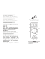
Familiarization (Fig.1)
1. Function/Range Switch: Selects the Function and Range desired.
2. COM Input Terminal: Ground input connector. 500V (DC + AC
Peak) Maximum voltage between COM and earth ground.
3. V Ω Input Terminal: Positive input connector for voltage, resistance,
and diode test. Maximum input rating is 1000VDC, 500VAC.
4. 200mA Input Terminal: Positive input connector for up to 200mA
current. Fused.
5. Lo Bat: Indicates batter is low.
OPERATING INSTRUCTIONS
Range Selection
If magnitude to be measured is unknown, always start with the high-
est range.
PRECAUTION!
Overload Condition: Range overload is indicated by a "1." Or by a "-
1." In the display with all other digits blanked. This is normal in the
ohms range when the leads are not connected to anything. In all other
situations, the user must take immediate steps to remove the cause of
DM2.Man.08.00 11/29/00 8:28 PM Page 3

– 4 –
the overload condition from the meter. Select the next higher range
until a value is displayed. If overload condition still exists in the
highest range, remove test leads from the measurement setup as it is
beyond the range of the meter.
1000
200
20
2
200
m
20
u
200
2m
20m
m
200
k
2000
500
OFF
200
2k
20k
200k
FUSED 200mA
MAX
500V
1000V
COM
V
V
A
V
DM2
5
4
3
2
1
Model DM2
Fig.1
DM2.Man.08.00 11/29/00 8:28 PM Page 4

– 5 –
VOLTAGE MEASUREMENT
1. Turn off power to the device under test and discharge all capacitors.
2. Set the Function/Range switch to the desired voltage type (AC or DC)
range.
3. Plug the black test lead into the COM jack on the DMM and connect
the test lead point to a grounded point (the reference point for mea-
surement of voltage).
4. Plug the red test lead into the V jack on the DMM and connect the test
lead point to the circuit where a voltage measurement is required.
Voltage is always measured in parallel across a test point.
5. Turn on power to the circuit/device to be measured and make the volt-
age measurement. Reduce the range setting if set too high until a sat-
isfactory reading is obtained.
6. After completing the measurement, turn off power to the circuit /
device under test, discharge all capacitors and disconnect the DMM
test leads.
CURRENT MEASUREMENT
1. Turn off power to the device under test and discharge all capacitors.
2. Set the Function/Range switch to the desired current range.
3. Plug the black test lead into the COM jack on the DMM and connect
the test return branch for the current to be measured.
4. Plug the red test lead into the 200mA current jack of the DM2.
Current measurements are always made with the meter in series with
the test branch. The circuit must be broken and the meter put in series
by placing the red test lead point to the test node for current.
5. Turn on power to the circuit/device under test and make the current
measurement. Reduce the range setting if set too high until a satisfac-
tory reading is obtained.
6. After completing the measurement, turn off power to the circuit/device
under test, discharge all capacitors, disconnect the DMM test leads
and re-connect the circuit branch.
Note: The current jack has a protective fuse installed to protect the
meter from damage and the user from harm if a current larger
than specified is applied at the input. If the quick acting fuse
blows, replace with a like fuse.
DM2.Man.08.00 11/29/00 8:28 PM Page 5

– 6 –
RESISTANCE MEASUREMENTS
1. Turn off any power to the resistance to be measured. Discharge any
capacitors. Any voltage present during a resistance measurement will
cause inaccurate readings and could damage the meter if exceeding
the overload protection of 500VDC or AC.
2. Set the Function/Range switch to the desired resistance range.
3. Plug the black test lead into the COM jack on the DMM and connect
the test lead point to one end of the resistor,
4. Plug the red test lead into the Ωjack on the DMM and connect the
test lead point to the other end of the resistor.
5. Adjust the Function/Range switch to the resistance range that gives the
most accurate measurement reading.
Note: Test lead resistance can interfere when making low resistance
measurements and should be subtracted from resistance readings
for accuracy. Select 200Ω range and make a firm contact
between the two test lead points (short them together). The dis-
play value is the test lead resistance to be subtracted from resis-
tance reading. Open circuits will be displayed as an overload
condition.
DIODE TEST
Diode Test checks the forward bias of diode function.
1. Turn off power to the device under test and discharge all capacitors.
2. Set the Function/Range switch to
3. Plug the black test into the COM jack on the DMM and connect the
test lead point to the cathode of the diode.
4. Plug the red test lead into the V Ωjack on the DMM and connect the
test lead point to the anode of the diode. The meter’s display indicates
the forward voltage drop (approximately 0.7V for silicone diode or
0.4V for germanium diode). Meter will display overload condition for
an open diode
5. Reverse the test lead connections to the diode to perform a reverse
bias test of the diode junction. A "1" (over-range) indicates a good
diode because a good diode junction has practically infinite resistance.
Notes: Overload conditions for both reverse and forward bias tests indi-
cate an open diode. A low voltage reading for both bias tests indicates
a shorted diode. If the diode is shunted by a resistor of 1000 ohms or
less, it must be removed from the circuit before taking the measure-
ment.
DM2.Man.08.00 11/29/00 8:28 PM Page 6

– 7 –
Bipolar transistor junctions may be tested in the same manner described
above as emitter-base and base-collector junctions are diode junc-
tions.
SPECIFICATIONS
General Specifications*
Display: 3 1/2 digit LCD, 1999 count.
Polarity: Automatic, positive implied, negative
indicated.
Zero: Automatic
Over-range: (1) or (-1) is displayed.
Low Battery: is displayed in the LCD when the battery
voltage drops below accurate operating
level.
Display Update: 3 per second, nominal.
Operating Temp: 0˚C to 50˚C, 0 to 70% Relative Humidity
Storage Temp: -20˚C to 60˚C, 0 to 80% R.H. with bat-
tery removed from meter.
Accuracy: Stated accuracy at 23˚C 5˚C, <75% R.H.
Power: Stated 9 volt battery NEDA1604, JIS
006P, IBC 6F22.
Battery Life: 200 hrs (Alkaline), 150 hours (Carbon-
Zinc)
Dimensions: (H x W x D) 4.7 x 2.7 x 1.1 inches (11.9 x
639 x 2.8 cm)
Weight: 5.5 ounces (156 grams)
Accessories: One pair test leads, one spare fuse, bat
tery, and Operator’s Manual.
*Specifications subject to change without notice
ELECTRICAL SPECIFICATIONS
DC Volts
Ranges: 200mV, 2V, 20V, 200V, 1000V
Accuracy: 0.8% RDG + 1 Digit
Input Impedance: 1MΩ
Resolution: 100mv
OL Protection:
200mV Range: 350VAC RMS/500VDC for 15 seconds
Other Ranges: 500VAC RMS/1000VDC for 60 seconds
DM2.Man.08.00 11/29/00 8:28 PM Page 7

– 8 –
AC Volts
Ranges: 200V, 500V
Accuracy: 1.2% RDG + 10 Digits
OL Protection: 500VAC RMS/500VDC
DC Current
Ranges: 200 A, 2mA, 20mA, 200mA
Resolution: 100nA
Accuracy: 1.2% RDG + 1 Digit
Voltage Burden: 350mV max
OL Protection: .8A/250V fuse
Resistance
Ranges: 200Ω, 2kΩ, 20kΩ, 200kΩ, 2MΩ
Accuracy: 200Ω Range:
1/8% RDG + 4 Digits
Other Ranges: 1.2% RDG + 2 Digits
OL Protection: 500VAC/VDC all ranges
Diode Test
Test Current: 1.0 0.6mA
Test Voltage: 3.2VDC max
MAINTENANCE
WARNING!
To prevent electrical shock hazard, turn off the multimeter and any device
or circuit under test and disconnect the test leads before removing the
battery hatch to the rear cover.
Troubleshooting
If there appears to be a malfunction during the operation of the meter, the
following steps should be performed in order to isolate the cause of
the problem:
1. Check the battery.
2. Review the operating instructions for possible mistakes in operating
procedure.
3. Inspect and test the test probes for a broken or intermittent connec-
tion.
DM2.Man.08.00 11/29/00 8:28 PM Page 8

– 9 –
4. Inspect and test the fuse. If it is necessary to replace the fuse, be sure
to install on of the proper current value. (See fuse replacement
below).
Battery Replacement
1. Remove the battery cover by gently sliding it toward the bottom of the
meter.
2. Remove and disconnect the old battery from the meter and replace
with a new NEDA type 1604 9 volt battery. Wind the excess lead
length once around the battery clip. Install the battery and replace the
battery cover.
Fuse Replacement
1. Remove the battery cover by gently sliding it towards the bottom of the
meter.
2. Remove the old fuse and replace with a new fuse of the proper rating.
The DM2 requires a 0.8A/250V quick-acting fuse, 5 x 20 mm.
WARNING!
To prevent fire, use a replacement fuse of the proper rating as shown
above.
Cleaning the Meter
Use only mild detergent and warm water to clean the meter. Do not use
aromatic hydrocarbons or chlorinated solvents.
REPAIR
Read the warranty located at the front of this manual before request-
ing warranty or non-warranty repairs. For warranty repairs, any mul-
timeter claimed to be defective can be returned to any Wavetek
Meterman authorized distributor or to a Wavetek Meterman Service
Center for an over-the-counter exchange for the same or like product.
Non-warranty repairs should be sent to a Wavetek Meterman Service
Center. Please call Wavetek Meterman or enquire at your point of
purchase for the nearest location and current repair rates. All multi-
meters returned for warranty of non-warranty repair or for calibration
should be accompanied by the following information or items: com-
pany name, customer’s name, address, telephone number, proof of
DM2.Man.08.00 11/29/00 8:28 PM Page 9

– 10 –
purchase (warranty repairs), a brief description of the problem or the
service requested, and the appropriate service charge (for non-war-
ranty repairs). Please include the lest leads with the meter. Service
charges should be remitted in the form of a check, a money order,
credit card with expiration date, or a purchase order made payable to
Wavetek Meterman or to the specific service center. For minimum
turn-around time on out-of-warranty repairs please phone in advance
for service charge rates. The multimeter should be shipped with
transportation charges prepaid to one of the following addresses or to
a service center
In U.S.A in Canada in Europe
Wavetek Meterman Wavetek Meterman Wavetek Meterman
1420 75th Street SW 400 Britannia Rd. E.Unit #1 52 Hurricane Way
Everett, WA 98203 Mississauga, ON L4Z 1X9 Norwich, NR6 6JB, U.K.
Tel: 1-877-596-2680 Tel: (905) 890-7600 Tel: int + 44-1603-404824
Fax: 425-446-6390 Fax: (905) 890-6866 Fax: int + 44-1603-482409
The instrument will be returned with the transportation charges paid
by Wavetek Meterman.
DM2.Man.08.00 11/29/00 8:28 PM Page 10

Manual Revision 08/00
Manual Part Number 1566172
Information contained in this
manual is proprietary to Wavetek
Meterman and is provided solely
for instrument operation and
maintenance. The information in
this document may not be dupli-
cated in any manner without the
prior approval in writing from
Wavetek Meterman.
Specifications subject to change.
Wavetek is a trademark of
Wavetek Wandel Golterman
© Wavetek Meterman, 2000
U.S. Service Center
Wavetek Meterman
1420 75th Street SW
Everett, WA 98203
Tel: (877) 596-2680
Fax: (425) 446-6390
Canadian Service Center
Wavetek Meterman
400 Britannia Rd. E.Unit #1
Mississauga, ON L4Z 1X9
Tel: (905) 890-7600
Fax: (905) 890-6866
European Distribution Center
Wavetek Meterman
52 Hurricane Way
Norwich, NR6 6JB, England
Tel: (44) 1603-404-824
Fax: (44) 1603-482-409
¤
TM
DM2.Man.08.00 11/29/00 8:28 PM Page 1
/