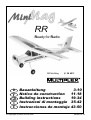
HiTEC MiniMag Owner's manual
- Category
- Remote controlled toys
- Type
- Owner's manual
This manual is also suitable for

1
F
GB
D
E
I
Bauanleitung 3-10
Notice de construction 11-18
Building instructions 19-34
Instruzioni di montaggio 35-42
Instrucciones de montaje 43-50
© Copyright by MULTIPLEX 2006 Version 02.1a
RR MiniMag # 26 4211
RR
Ready for Radio

2
D
F
GB
I
E
Sicherheitshinweise
☺
Prüfen Sie vor jedem Start den festen Sitz des Motors und der Luftschraube - insbesondere nach dem Transport, härteren Landungen
sowie Abstürzen. Prüfen Sie ebenfalls vor jedem Start den festen Sitz und die richtige Position der Tragflächen auf dem Rumpf.
☺ Akku erst einstecken, wenn Ihr Sender eingeschaltet ist und Sie sicher sind, daß das Bedienelement für die Motorsteuerung auf "AUS"
steht.
☺ Im startbereiten Zustand nicht in den Bereich der Luftschraube greifen.
Vorsicht in der Luftschraubendrehebene - auch Zuschauer zur Seite bitten!
☺ Zwischen den Flügen die Motortemperatur durch vorsichtige Fingerprobe prüfen und
vor einem Neustart den Motor ausreichend abkühlen lassen. Die Temperatur ist richtig, wenn Sie den Motor problemlos berühren
können. Insbesondere bei hohen Außentemperaturen kann dieses bis zu 15 Minuten dauern.
☺ Denken Sie immer daran: Niemals auf Personen und Tiere zufliegen.
Conseils de sécurité
☺
Avant chaque décollage, vérifiez la fixation du moteur et de l'hélice, notamment après le transport, après les atterrissages violents et
après un “Crash”. Vérifiez également, avant chaque décollage la fixation ainsi que le positionnement de l’aile par rapport au fuselage.
☺ Ne branchez l’accu de propulsion que si vous êtes sûr que votre émetteur est allumé et que l’élément de commande moteur est en
position “ARRET”.
☺ Ne mettez pas vos doigts dans l’hélice! Attention à la mise en marche, demandez également aux spectateurs de reculer.
☺ Entre deux vols, vérifiez en posant un doigt dessus, la température du moteur, laissezle refroidir suffisamment avant le prochain
décollage. La température est correcte si vous pouvez maintenir votre doigt ou votre main sur le moteur. Le temps de refroidissement
peut varier jusqu’à 15 minutes s’il fait particulièrement chaud.
☺ Pensez-y toujours: ne volez jamais vers ou au-dessus des personnes ou des animaux.
Safety notes
☺
Before every flight check that the motor and propeller are in place and secure - especially after transporting the model, and after hard
landings and crashes. Check also that the wing is correctly located and firmly secured on the fuselage before each flight.
☺ Don’t plug in the battery until you have switched on the transmitter, and you are sure that the motor control on the transmitter is set to
“OFF”.
☺ When the model is switched on, ready to fly, take care not to touch the propeller. Keep well clear of the propeller disc too, and ask
spectators to stay back.
☺ Allow the motor to cool down after each flight. You can check this by carefully touching the motor case with your finger. The
temperature is correct when you can hold your finger on the case without any problem. On hot days this may take up to 15 minutes.
☺ Please keep in mind at all times: don’t fly towards people or animals.
Note di sicurezza
☺ Prima di ogni decollo controllare che il motore e la eliche siano fissati stabilmente - specialmente dopo il trasporto, atterraggi duri e se il
modello è precipitato. Controllare prima del decollo anche il fissaggio e la posizione corretta delle ali sulla fusoliera.
☺ Collegare la batteria solo quando la radio è inserita ed il comando del motore è sicuramente in posizione ”SPENTO”.
☺ Prima del decollo non avvicinarsi al campo di rotazione della eliche. Attenzione alla eliche in movimento - pregare che eventuali spettatori
si portino alla dovuta distanza di sicurezza!
☺ Tra un volo e l’altro controllare cautamente con le dita la temperatura del motore e farli raffreddare sufficientemente prima di ogni nuovo
decollo. La temperatura è giusta se si possono toccare senza problemi. Specialmente con una temperatura esterna alta questo può
durare fino a 15 minuti.
☺ Fare attenzione: Non volare mai nella direzione di persone ed animali.
Advertencias de seguridad
☺ Compruebe antes de cada despegue que el motor y la hélice estén fuertemente sujetados, sobretodo después de haberlo transportado,
de aterrizajes más fuertes así como después de una caída. Compruebe igualmente antes de cada despegue que las alas estén bien
sujetas y bien colocadas en el fuselaje.
☺ Conectar la batería, cuando la emisora esté encendida y Usted esté seguro que el elemento de mando para el motor esté en ”OFF”.
☺ No meter la mano en la zona inmediata a la hélice cuando el avión esté a punto de despegar. ¡Cuidado con la zona de la hélice! ¡Pedir a
los espectadores que se aparten!
☺ Entre los vuelos hay que comprobar cuidadosamente la temperatura del motor con el dedo y dejar que el motor se enfríe antes de volver
a despegar. La temperatura es correcta, si puede tocar el motor sin problemas. Sobretodo en el caso de temperaturas del ambiente muy
altas, esto puede tardar unos 15 minutos.
☺ Recuerde: No volar nunca hacía personas o animales.
Page is loading ...
Page is loading ...
Page is loading ...
Page is loading ...
Page is loading ...
Page is loading ...
Page is loading ...
Page is loading ...
Page is loading ...
Page is loading ...
Page is loading ...
Page is loading ...
Page is loading ...
Page is loading ...
Page is loading ...
Page is loading ...

19
RR # 26 4211
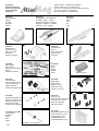
Examine your kit carefully!
MULTIPLEX model kits are subject to constant quality checks throughout the production process, and we sincerely
hope that you are completely satisfied with the contents of your kit. However, we would ask you to check all the parts
before you start construction, as we cannot exchange components which you have already worked on. If you
find any part is not acceptable for any reason, we will readily correct or exchange it. Just send the component to our
Model Department. Please be sure to include the purchase receipt and a brief description of the fault.
We are constantly working on improving our models, and for this reason we must reserve the right to change the kit
contents in terms of shape or dimensions of parts, technology, materials and fittings, without prior notification. Please
understand that we cannot entertain claims against us if the kit contents do not agree in every respect with the
instructions and the illustrations.
Caution!
Radio-controlled models, and especially model aircraft, are by no means playthings. Building and operating
them safely requires a certain level of technical competence and manual skill, together with discipline and
a responsible attitude at the flying field. Errors and carelessness in building and flying the model can result
in serious personal injury and damage to property. Since we, as manufacturers, have no control over the
construction, maintenance and operation of our products, we are obliged to take this opportunity to point out
these hazards and to emphasise your personal responsibility.
Additional items required for the Mini Mag:
Adhesive and activator:
Use medium-viscosity cyano glue (
not styrofoam cyano). It is important to use activator when using cyano. Epoxy
adhesives produce what initially appears to be a sound joint, but the bond is only superficial, and the hard resin breaks
away from the parts under load.
Hot-melt glues can also be used.
MULTIPLEX radio control system components for the Mini Mag:
e.g. PiCO 5/6 UNI receiver 35 MHz A Order No. 5 5920
alternatively 40 MHz Order No. 5 5921
or Micro IPD UNI receiver 35 MHz A Order No. 5 5971
alternatively 40 MHz Order No. 5 5972
plus optionally:
Nano S UNI or HS 55 servo (2 required) Ailerons Order No. 6 5120
UNI extension lead, 300 mm Aileron servo, 2 x Order No. 8 5031
if required: UNI separation filter lead, 200 mm Aileron servo, 2 x Order No. 8 5035
plus optionally:
Magicmixer #1 for three-channel RC transmitter with no mixers Order No. 7 3000
UNI Y-lead for four-channel RC transmitter with sep. rudder control Order No. 8 5030
Flight batteries:
e.g. MULTIPLEX Permabatt NiMH battery (AA cells), 7 / 1500 mAh Order No. 15 6030
or MULTIPLEX Permabatt NiMH battery (AA cells), 8 / 1500 mAh Order No. 15 6037
or MULTIPLEX LiBatt (LiPo) P-CS, 2 / 1-2000 mAh Order No. 15 7016
or MULTIPLEX LiBatt (LiPo) SX-BX, 2 / 1-2100 mAh Order No. 15 7130
Battery charger:
MULTIcharger LN-5014 DC (charge current 100 mA … 5 A) Order No. 9 2531
1 - 14 NiCd / NiMH cells and 1 - 5 Lithium-Polymer cells
Options:
Float set Order No. 73 3069
Upgrade 1: Easy Glider power set (3 : 1 geared Permax 400) Order No. 33 2688
plus 3.5 mm Ø driver Order No. 33 2310
and propeller, 8 x 3.8” Order No. 73 3139
Upgrade 2: “Sport” power set, BL-X 22-18
Contents: motor, propeller driver, speed controller and propeller Order No. 33 2627
Tools: Scissors, balsa knife, combination pliers, slot-head and cross-point screwdrivers (servo output arms and motor
retaining screws), soldering iron if required.
Note: please remove the illustration pages from the centre of the instructions.
GB

20
Specification:
Wingspan 1010 mm
Overall fuselage length 820 mm
All-up weight min. 580 g
Wing loading (FAI) min. 26 g/dm²
Power system min. Permax 400 6 V
RC functions: Rudder, elevator and motor; optional rudder
Important note
This model is not made of styrofoam™, and it is not
possible to glue the material using white glue or
epoxy. Please be sure to use cyano-acrylate glue
exclusively, preferably in conjunction with cyano
activator (kicker). We recommend medium-viscosity
cyano. This is the procedure: spray cyano activator
on one face of the Elapor®; allow it to air-dry, then
apply cyano adhesive to the other face. Join the parts,
immediately position them accurately, and wait a few
seconds for the glue to harden.
Please take care when handling cyano-acrylate
adhesives. These materials harden in seconds, so don’t
get them on your fingers or other parts of the body.
We strongly recommend the use of goggles to protect
your eyes. Keep the adhesive out of the reach of
children.
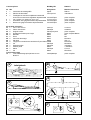
1. Before assembling the model
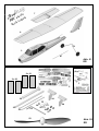
Please check the contents of your kit.
You will find Figs. 01 + 02 and the Parts List helpful here.
The illustrations which refer to completing your RR model
are marked RR + KIT. The pictures marked with KIT only
are just for your information, in case you need to repair the
model at any time using replacement parts.
2. Opening and closing the canopy
Hold the front of the canopy moulding and pull it upward;
this opens the canopy.
To close it again, insert the rear locating lug, push the
canopy back as far as it will go, and press down the front
until it engages.
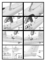
Final assembly
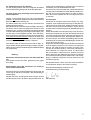
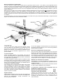
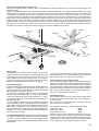
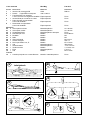
3. Tailwheel option
A tailwheel can be fitted to the model if you wish. This is
optional for the land-based version, but is essential if you
intend to install floats later, because a water rudder is
required for this version, and this is fitted to the tailwheel
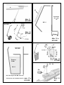
wire. Figs. 09 - 13 show the procedure.
A bending template is shown in Figs. 12 + 12a. The steel
wire 47 has a diameter of 1.3 mm. The sleeve 35 is supplied
in the kit.
Installation:
Pierce a tunnel through the tailplane and the fuselage as
shown in Fig. 11. Note that the foam tailskid has to be cut
away if you fit the optional tailwheel. Cut a notch in the
rudder for the actuating wire. Fig. 10.
Glue the sleeve 35 in place using cyano, and cut it to
length as shown. The final, upper bend in the tailwheel
wire 47 should only be made after fitting it through the
sleeve 35.
One further option:
For float operations a water rudder has to be cut from 3
mm Depron. It is fixed between the wire frame using
adhesive tape, and attached to the tailwheel wire using
two collets. These parts are included in the float set.
4. Installing the motor
The model is fitted with a Permax 400 motor as standard.
However, you may wish to install an upgrade power plant.
We recommend the following two options:
A. Standard G Permax 400 with 3 : 1 gearbox Fig. 20
Easy Glider E power set
(3 : 1 gearbox with Permax 400) # 33 2688
plus 3.5 mm Ø propeller driver # 33 2310
and 8 x 3.8” propeller # 73 3139
B. “Sport” power set BL-X 22-18 # 33 2627
This includes speed controller, propeller driver and propeller
5. Connecting the motor
Carry out a test-run! The motor shaft / propeller must rotate
anti-clockwise when viewed from the front. If not, reverse
the connections at the motor terminals.
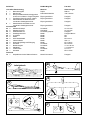
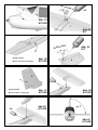
6. Releasing the elevator and rudder
Move the rudder and elevator to and fro repeatedly at the
hinge line to free up the hinges. Do not cut off the control
surfaces! Figs. 25 + 27
7. Gluing the tail panels to the fuselage
Position the tailplane on the fuselage “dry” (no glue), and
check that the parts fit together accurately. Ensure in
particular that the tailplane 7 rests on the fuselage without
any gaps, and is parallel to the wing saddle. Check this
by laying the wing on the fuselage and sighting over the
wing and tailplane from the nose. When you are confident
that the tailplane can be aligned properly, it should be glued
permanently to the fuselage. Check alignment once more,
and ensure that it fits snugly before allowing the glue to
cure fully.
Place the fin on the fuselage “dry”, and check that it fits
correctly. In this case ensure that the fin 8 makes good
contact, without gaps, and is at 90° to the wing saddle
and the tailplane. Use a setsquare to check this.
Fig. 30
8. Retaining the elevator and rudder pushrods
Slip the end of the two steel pushrods 41 and 42 through
the pushrod connectors 25. Set the servos and control
surfaces to centre (neutral) and tighten the socket-head
grubscrews 28 to lock them. You may need to bend the
pushrods slightly to obtain proper alignment.
Figs. 31 - 32
9. Installing the undercarriage
The undercarriage is supplied pre-assembled; compress
the unit gently and allow it to snap into the holder 74.
Install the screw 75. Fig. 34

21
Optional ailerons
If you wish to fly the model with just rudder / elevator
controls, skip stages 10 - 14 Abb.36-39. The servo wells
can be sealed later using the decals supplied.
The model flies equally well as a rudder / elevator or “full-
house” model with the same dihedral. This means that
you can convert the model to aileron control at any time.
……………………………….
If you wish to fly the model with aileroms („full-house“
control), resume construction at this point:
10. Releasing the ailerons, installing the aileron
servos
Cut through the wing 6 at both ends of the ailerons to
release them. Move the ailerons to and fro repeatedly at
the hinge line to free up the hinges. Do not cut off the
ailerons!
Fig. 36
11. Installing the aileron servos
Set the servos to “neutral” from the transmitter. Fit the
output arms on the servos so that the arms are at 90° to
the long case sides; prepare one left-hand servo and one
right-hand servo in this way.
Offer up the servos to the moulded recesses in the wing 6;
you may need to make minor adjustments to suit the servos
you intend to fit. Apply a drop of hot-melt glue in the slots
in the wing for the servo mounting lugs, and immediately
press the servo into the recess. Apply a little more glue
afterwards if necessary.
Fig. 37
12. Deploying the aileron servo leads
Deploy the servo leads towards the wing centre; you may
need to use extension leads. Place the lead in a straight
line along the front edge of the spar well, standing on edge.
The leads must project by about 120 mm at the wing root,
so that they can be connected to the receiver when you
assemble the model. Fix the leads in the centre of the
wing with a drop of hot-melt glue.
13. Attaching the aileron horns
Insert the pushrod connectors 25 in the outermost hole in
the aileron horns 24. Secure them with the washers 26
and nuts 27. Caution: prepare one left-hand horn, one
right-hand horn! Tighten the nuts carefully (don’t overtighten
them), and secure each with a tiny drop of paint or cyano,
applied on a pin. Fit the socket-head grubscrews 28 in the
pushrod connectors 25 using the allen key 29. Glue the
horns 24 in the recesses in the ailerons using activator
and cyano; the row of holes must be at the hinge line.
Fig. 38
14. Installing the aileron pushrods
Connect the pre-formed end of the steel pushrods 30 to
the innermost hole of the servo output arms, and slip the
plain end through the pushrod connectors 25. Set the
ailerons and servos to neutral and tighten the grubscrews
28 to lock them.
Fig. 39
……………………………………..
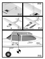
15. When the model is assembled, the wing is attached to
the fuselage using the plastic screw 32. Fig. 40
16. Installing the receiving system
The remaining RC system components can now be installed
in the cabin area, and the flight battery installed. It is
important to position the battery in such a way that the
model balances at the stated CG position. See Fig. 43.
It is possible to fit many different types and shapes of
battery in the front end of the fuselage. If it is not possible
to obtain the correct CG by re-positioning the battery, lead
ballast can be fitted at the nose or tail.
The kit is supplied with self-adhesive hook-and-loop tape
20 + 21 for securing the RC components. However, the
adhesive on the tape is not always adequate, so it should
also be glued in place with cyano.
Place the receiver vertically in the fuselage, behind the
wing retaining screw. Run the wire aerial out of the fuselage
and tape it to the underside at the tail. The excess length
can simply be left trailing freely.
The motor supplied is fitted with basic suppressors as
standard, and this level of suppression is adequate provided
that you use the recommended MULTIcont X-16 speed
controller, # 7 2271.
If you wish to use a different controller, it is advisable to fit
additional suppressors to the motor. A suppressor set is
available for this purpose under # 8 5020. Solder one 47
nF capacitor between each motor terminal and the motor
can, and the third 47 nF capacitor between the motor
terminals to form a bridge.
Fitting the propeller
Before the first test run the propeller has to be fitted on the
motor shaft. Please check that the propeller is firmly fixed.
The spinner and propeller should be pushed onto the motor
shaft and secured with a drop of glue after roughening the
shaft with abrasive paper. For the Günther propeller use 5-
minute epoxy; cyano works better with the MPX propeller.
When you have completed the wiring you can carry out an
initial test-run, but please allow the glue to harden before
you do this.
Don’t connect the battery to the speed controller until
you have switched the transmitter on, and have
checked that the throttle control is at the “OFF”
position.
Switch the transmitter on, connect the flight battery in the
model to the speed controller, and the controller to the
receiver. The controller you use must be what is known as
a BEC type, i.e. with an integral receiver power supply
drawn from the flight battery.
Now switch the motor on briefly and check once more that
the propeller is rotating in the correct direction. Note: when
test-running the motor always remove all light objects from
the area in front of and behind the model, and hold the
aeroplane firmly.
Caution: even small motors and propellers are
capable of inflicting painful injuries!

22
17. Setting the control surface travels
It is important to set the control surface travels correctly,
as these settings have a crucial influence on the model’s
overall control response. In all cases the travels are
measured at the point of maximum chord (width of control
surface.
Elevator
up - stick back - approx. + 11 mm
down - stick forward - approx. - 11 mm
Rudder
left and right each way - approx. 6-10 mm
Ailerons
up - approx. + 7 mm
down - approx. - 3 mm
MagicMixer #1 (optional) # 7 3000
The MagicMixer #1 permits the use of a simple radio control
transmitter without mixer functions. It is adequate for:
MINI MAG 3-channel RC transmitter
Without the MagicMixer #1 you will need at least a four-
channel computer transmitter with mixer functions.
Using this module the Mini Mag can be flown even with a
transmitter such as the Ranger III, as supplied with the
EasyStar and SpaceScooter RTF models.
It provides a means of controlling
two aileron servos and
the rudder from a single channel (right / left output) at the
receiver.
The servos, and therefore the control surface travels, are
automatically actuated with the correct deflections. Using
the MagicMixer #1 the degree to which the rudder follows
the ailerons (“combi-switch” / CAR function) and the aileron
differential are fixed, i.e. they cannot be altered.
Aileron differential means that the up-aileron travel is greater
than the down-aileron travel. This helps to prevent the model
swinging away from the turn (adverse yaw) when ailerons
are applied.
If you are using the MagicMixer #1 your transmitter must
offer at least the following channels:
Channel 1: Ailerons, coupled rudder (3 servos)
Channel 2: Elevator (1 servo)
Channel 3: Throttle (1 servo)
Connect the aileron servo leads as described in the
“MagicMixer #1” instructions. Take care to maintain
correct polarity when making these connections: the signal
pin is indicated on the label of the MagicMixer with the
square signal symbol. The signal wire in the servo lead is
generally yellow or orange.
Connections at the MagicMixer #1:
r/l = to receiver, right / left output
AR = to right aileron servo
AL = to left aileron servo
R = to rudder servo
If necessary, set the correct direction of servo travel using
the servo reverse facility on your transmitter.
Y-lead for the aileron servos (optional) # 8 5030
The Y-lead permits the use of a simple four-channel radio
control transmitter, i.e. without mixer functions. The two
aileron servos are actuated simultaneously by a
single
receiver servo output.
Please note: in this case the differential aileron movement
must be obtained by mechanical means. This is achieved
by offsetting the servo output arms forward by two splines.
This must be done before you install the servos. The rudder
is controlled via a separate channel with this arrangement.
Computer radio control transmitter
If you have this type of transmitter you need neither a
MagicMixer #1 nor a Y-lead.
The transmitter must feature the following adjustment
facilities:
- Aileron differential mixer
- Servo reverse
- Servo travel adjustment
- Optional combi-switch (coupled rudder / ailerons)
Note: when you apply a right-aileron command at
the transmitter, the right-hand aileron (as seen from
the tail) must deflect up.
If you find that you cannot set the correct control
surface travels with your radio control system, you
will need to change the linkage hole to which the
pushrod is connected.
18. Gilding the lily
The kit includes a multi-colour decal sheet. Cut out the
individual name placards and emblems and apply them to
the model, either following our scheme (kit box illustration)
or using your own arrangement. If you have built the rudder
/ elevator version of the model, you will find decals on the
sheet designed for covering the servo recesses in the wing.
29. Balancing
To make your Mini Mag fly safe and stable it must be
balanced at the correct point or C.G. (Centre of gravity) -
just like every other aircraft. Assemble your model
completely, ready to fly, and install the flight battery.
The Centre of Gravity should be at a point 67 mm aft of
the leading edge of the wing, measured where the wing
meets the fuselage. You will find the markings moulded on
the underside of the wings.
Support the model on your fingertips at the marked point,
and it should balance level. If necessary, adjust the position
of the flight battery until the plane wings levels. Once the
correct position is found, mark it inside the battery box to
ensure that the battery is always replaced in exactly the
same location. Fig. 43
20. Preparing for the first flight
Wait for a day with as little breeze as possible for the first
flight. The evening hours often provide the best conditions.

23
Abb. 01
RR
2 x 20
# 26 4211
Abb. 02
RR
RR
Ready for Radio
24
25
26
27
28
29
30
32
35
47
52
70
80
1
2
3
6
7
8
24
2 x 21

24
Abb. 03
KIT
Abb. 05
KIT
Abb. 04
KIT
Abb. 06
KIT
30
Abb. 07
KIT
Abb. 09
KIT+RR
Abb. 08
KIT
Abb. 10
RR
3
4
Hot
glue
CA
Hot
glue
CA
CA
CA
Ø 26
# 73 3199
Depron
8
Heckrad=Option. Die Teile
liegen dem BK nicht bei!
Tailwheel = option. Parts not
included in the kit
20 mm
20 mm
43
45
41
44
46
42
22
22
4
3

25
Abb. 11
KIT+RR
Abb. 12
KIT+RR
Abb. 13
KIT+RR
Abb. 12 a
KIT+RR
Abb. 14
KIT
Abb. 13 a
KIT+RR
Stahl/Steel
Ø 1,3 mm
Depron
3 mm
Die Teile liegen dem BK nicht bei!
These parts not included in the kit
Stahl/Steel
Ø 1,3 mm
33 - 34
CA
4
4
Stahl/Steel
Ø 1,3 mm
M 1:1
M 1:1
35
47
47
18mm
Page is loading ...

27
Abb. 23
KIT+RR
Abb. 25
KIT+RR
Abb.24
KIT
30
Abb. 27
KIT+RR
Abb. 28
KIT+RR
Abb.30
KIT+RR
Abb.29
KIT+RR
5
28 25 24 26 27
CA
CA
CA
7
8
gängig machen!
Move to and fro to ease hinge
!
7
gängig machen!
Move to and fro to ease hinge
8
28 25 24 26 27
Abb. 26
KIT
CA
Page is loading ...
Page is loading ...

30
Ersatzteile (bitte bei Ihrem Fachhändler bestellen)
Replacement parts (please order from your model shop)
Pièces de rechanges (S.V.P. à ne commander que chez votre revendeur)
Parti di ricambio (da ordinare presso il rivenditore)
Repuestos (por favor, diríjase a su distribuidor)
# 22 4176
Kabinenhaube
Canopy
Verrière
Capottina
Cabina
# 22 4175
Rumpfhälften + Bowdenzüge
Fuselage shells + snakes
Moitié de fuselage + tringlerie
Semigusci fusoliera + bowden
Fuselaje + trans. bowden
# 22 4179
Kleinteilesatz
Small items set
Petit nécessaire
Minuteria
Piezas pequeñas
# 72 4388
Dekorbogen
Decal sheet
Planche de décoration
Decals
Lámina decorativa
# 22 4180
Fahrwerkssatz
Undercarriage compon.
Train d’atterrissage
Parti per carrello
Kit del tren de aterrizaje
# 70 3455
Gestängeanschluss (2x)
Pushrod connector (2x)
Element de fixitation (2x)
Raccordo rinvii (2x)
Conexión del verillaje(2x)
# 72 4279 / # 72 4293
Luftschraube
Propeller
Hélice
Elica
Hélice
# 22 4178
Leitwerkssatz
Tail set
Kit de gouvernes
Piani di coda
Timones
# 33 2545
Motor
Motor
Moteur
Motore
Motor
# 33 2699
Motorträger
Motor mount
Support moteur
Supporto motore
Soporte del motor
# 72 5136
Canopy-Lock
Kabinenhaubenverschluss
Fermeture de verrière
Chiusura capottina
Cierre de cabina
# 71 3340
Schraube M5x50mm (10x)
Screw M5x50mm (10x)
Vis M5x50mm (10x)
Vite M5x50mm (10x)
Tornillo M5x50mm (10x)
Permax 400 6V
5,0x4,0" / 12,7x10,2cm
# 22 4177
Tragfläche
panel
Aile
Ali
Alas
# 72 3135

31
Be sure to carry out a range check before the first
flight!
The transmitter battery and flight pack must be fully charged
according to the instructions. Ensure that the channel you
are using is not already in use
before you switch on the
transmitter.
Collapse the transmitter aerial, and ask a friend to walk
away from you holding the transmitter.
As he walks away your friend should constantly operate
one control function while you watch the model’s servos.
The servo not being operated should stay motionless up
to a range of around 60 m, and the other servo should
follow the transmitter stick movements smoothly and
immediately. This test only provides meaningful results if
the radio band is “clean” (not suffering interference), and if
no other radio control transmitters are switched on,
even if
they are on different channels. If successful, repeat the
check with the motor running. The effective range should
not be significantly reduced when the motor is running.
If you are not sure about anything, do not fly the model! If
you cannot eliminate the problem send the whole radio
control system (including battery, switch harness, servos)
to the manufacturer’s service department for checking.
The first flight ....
Do not test-glide this model!
The model is designed for hand-launching - always exactly
into the wind.
We recommend that you ask an experienced
modeller to help you during the first flight.
Allow the model to climb to a safe altitude, then adjust the
trims on the transmitter so that the model flies straight
ahead without any help from you.
At a safe height switch off the motor and make yourself
familiar with the model’s control response on the glide.
Carry out a dummy landing approach at a good height, so
that you will feel confident about the real landing when the
flight pack is flat.
Don’t attempt tightly banked turns close to the ground at
first, and especially not on the landing approach.
It is always better to land safely some distance away, and
have to walk to collect the model, than to risk damaging it
by dragging it close to your feet.
21. Safety
Safety is the First Commandment when flying any model
aircraft. Third party insurance should be considered a basic
essential. If you join a model club suitable cover will usually
be available through the organisation. It is your personal
responsibility to ensure that your insurance is adequate
(i.e. that its cover includes powered model aircraft).
Make it your job to keep your models and your radio control
system in perfect order at all times. Check the correct
charging procedure for the rechargeable batteries used in
your RC set. Make use of all sensible safety systems and
precautions which are advised for your system. An excellent
source of practical accessories is the MULTIPLEX main
catalogue, as our products are designed and manufactured
exclusively by practising modellers for other practising
modellers.
Always fly with a responsible attitude. You may think that
flying low over other people’s heads is proof of your piloting
skill; others know better. The real expert does not need to
prove himself in such childish ways. It is in all our interests
that you let other pilots know that this is also what you
think. Always fly in such a way that you do not endanger
yourself or others. Bear in mind that even the best RC
system in the world is subject to outside interference. No
matter how many years of accident-free flying you have
under your belt, you have no idea what will happen in the
next minute.
We - the MULTIPLEX team - hope you have many hours of
pleasure building and flying your new model.
Klaus Michler
Product development
MULTIPLEX Modellsport GmbH & Co. KG

32
Parts List MiniMag RR kit # 26 4211
Part No. Description Material Dimensions
No. off
1 1 Building instructions, RR Paper A4
2 1 Decal sheet Printed adhesive film 400 x 700 mm
3 1 Fuselage and cabin, factory-assembled,
two servos, motor and controller installed Elapor foam Ready made
6 1 Wing, factory-assembled, for R / E version Elapor foam Ready made
7 1 Tailplane with horn and pushrod connector fitted Elapor foam Ready made
8 1 Fin with horn and pushrod connector fitted Elapor foam Ready made
Small parts set
20 2 Hook-and-loop tape, hook Plastic 25 x 60 mm
21 2 Hook-and-loop tape, loop Plastic 25 x 60 mm
24 2 Glue-fitting horn Inj. moulded plastic Ready made
25 2 Pushrod connector, 6 mm Ø Metal Ready made
26 2 Washer Metal M2
27 2 Nut Metal M2
28 2 Socket-head grubscrew Metal M3 x 3 mm
29 1 Allen key Metal 1.5 mm A/F
30 2 Pre-formed aileron pushrod Metal 1 Ø x 70 mm
32 1 Screw Plastic M5 x 50 mm
35 1 Snake outer sleeve Plastic 3 x 2 x 90 mm
47 1 Steel rod Metal 1.3 Ø x 250 mm
52 1 Propeller Plastic 5.0 x 4.0”
75 1 Screw Metal M3 x 12 mm
Undercarriage
70 1 Main undercarriage with two 53 mm Ø wheels Metal / plastic Ready made
CD instructions / video
80 1 CD instructions / video Ready made
A B
C
D
E
Auftriebskraft
X
α
F

33
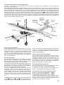
Fuselage
Canopy
L.H. wing
panel
Rudder
Elevator
Fin
Tailplane
R.H. wing
panel
Longitudinal axis
normal axis
lateral axis
GB
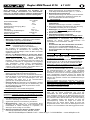
Basic information relating to model aircraft
Any aircraft, whether full-size or model, can be controlled around the three primary axes: vertical (yaw), lateral (pitch) and
longitudinal (roll).
When you operate the elevator, the model’s attitude alters around the lateral axis. If you apply a rudder command, the model
swings around the vertical axis. If you move the aileron stick, the model rolls around its longitudinal axis. As our EasyStar has
considerable wing dihedral, ailerons are not required for roll control. In this case the rudder is used both to turn the model
around the vertical axis, and also to roll it (longitudinal axis). External influences such as air turbulence may cause the model to
deviate from its intended flight path, and when this happens the pilot must control the model in such a way that it returns to the
required direction. The basic method of controlling the model’s height (altitude) is to vary motor speed (motor and propeller). The
rotational speed of the motor is usually altered by means of a speed controller. Applying up-elevator also causes the model to
gain height, but at the same time it loses speed, and this can only be continued until the model reaches its minimum airspeed
and stalls. The maximum climb angle varies according to the power available from the motor.
Wing section
The wing features a cambered airfoil section over which the
air flows when the model is flying. In a given period of time the
air flowing over the top surface of the wing has to cover a
greater distance than the air flowing under it. This causes a
reduction in pressure on the top surface, which in turn creates
a lifting force which keeps the aircraft in the air. Fig. A
Centre of Gravity (CG)
To achieve stable flying characteristics your model aircraft must
balance at a particular point, just like any other aircraft. It is
absolutely essential to check and set the correct CG position
before flying the model for the first time.
The CG position is stated as a distance which is measured aft
from the wing root leading edge, i.e. close to the fuselage.
Support the model at this point on two fingertips (or - better -
use the MPX CG gauge, # 69 3054); the model should now
hang level. Fig. B
If the model does not balance level, the installed components
(e.g. flight battery) can be re-positioned inside the fuselage. If
this is still not sufficient, attach the appropriate quantity of trim
ballast (lead or plasticene) to the fuselage nose or tail and
secure it carefully. If the model is tail-heavy, fix the ballast at the
fuselage nose; if the model is tail-heavy, attach the ballast at
the tail end of the fuselage.
The longitudinal dihedral is the difference in degrees between
the angle of incidence of the wing and of the tail. Provided that
you work carefully and attach the wing and tailplane to the
fuselage without gaps, the longitudinal dihedral will be correct
automatically.
If you are sure that both these settings (CG and longitudinal
dihedral) are correct, you can be confident that there will be no
major problems when you test-fly the model. Fig. C
Control surfaces, control surface travels
The model will only fly safely, reliably and accurately if the control
surfaces move freely and smoothly, follow the stick movements
in the correct “sense”, and move to the stated maximum travels.
The travels stated in these instructions have been established
during the test-flying programme, and we strongly recommend
that you keep to them initially. You can always adjust them to
meet your personal preferences later on.
Transmitter controls
The transmitter features two main sticks which the pilot moves
to control the servos in the model, which in turn operate the
control surfaces.
The functions are assigned according to Mode A, although
other stick modes are possible.
The transmitter controls the control surfaces as follows:
Rudder (left / right) Fig. D
Elevator (up / down) Fig. E
Throttle (motor off / on) Fig. F
Unlike the other controls, the throttle stick must not return to
the neutral position automatically. Instead it features a ratchet
so that it stays wherever you put it. Please read the instructions
supplied with your radio control system for the method of setting
up and adjusting the transmitter and receiving system.

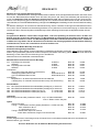
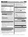
MULTIcont X-16 speed controller # 7 2271
MULTIPLEX Modellsport GmbH & Co. KG • Neuer Weg 2 • D-75223 Niefern • www.multiplex-rc.de
MULTICont
X
-16 instructions # 72271
These operating instructions are an integral part of this
product. They contain important information and safety
notes, and should therefore be kept in a safe place at all
times. Be sure to pass them on to the new owner if you
ever dispose of the product.
1. S
PECIFICATION
MULTIcont X-16
Cell count, Ni-Cd / Ni-MH
6 - 8 /
2 Li-Poly cells
Continuous current 16 A
Pulse frequency ~ 6 kHz
Receiver power supply (BEC):
BEC voltage 5 V
BEC current max. 1 A
Dissipated power of BEC controller max. 2.5 W
Dimensions (excl. cables) 27 x 20 x8 mm
Weight incl. cables 17 g
2. S
AFETY NOTES
• Read the instructions before using the controller.
• Avoid heat build-up: do not obstruct air circulation.
• Do not connect drive battery with reversed polarity:
Incorrect polarity at the battery terminals will instantly
ruin the speed controller.
For this reason: • red wire to POSITIVE terminal (+),
• black wire to NEGATIVE terminal (-)
If you do not wish to solder the motor connections directly,
we recommend the use of MPX 6-pin connectors # 85213 /
85214 for connecting the controller / battery and motor /
controller.
• When soldering or working on the motor or controller:
Always disconnect the battery
(short-circuit / injury hazard).
• When test-running or operating the power system:
Do not hold the motor in your hand when running it; hold the
model securely. Check that there is ample space for the
propeller to rotate. Remove any object from the vicinity of
the propeller which could be sucked into it or blown away by
it (clothing, small items, paper etc.). Never stand in or in
front of the plane of rotation of the propeller (injury hazard).
3. S
PECIAL FEATURES
• BEC with low-voltage cut-off: (recommended up to max. 8
cells) with automatic cell count detection.
• Power-on guard: when you connect the drive battery, the
controller stays in power-on guard mode. The motor can
only be switched on if you move the throttle stick to the idle
position after connecting the battery. If not, the LED flashes.
• Overload protection: if the controller overheats or is
overloaded, the controller switches off the power supply to
the motor. To re-activate the system you must disconnect
the battery, then re-connect it.
• Over-voltage protection:
The controller switches off if the voltage is above 16 V.
4. C
ONNECTING THE CONTROLLER TO THE MOTOR
Note: to connect the controller soldering may be necessary.
Soldering requires a certain level of skill and care, as the
system will only work reliably if the joints are made well:
• use only a type of solder designed for electronic work
• do not use acid-based soldering flux
• do not over-heat parts or heat them for too long
• if you are not sure, ask an experienced modeller to help
1. Motor suppression:. if the motor you wish to use is not
supplied with factory-fitted suppressors, we strongly
recommend that you fit the suppressor set, # 85020, to
avoid interference to the RC system.
2. Solder the controller’s motor cables to the motor
The motor cables on the controller are marked “MOTOR”;
solder them to the drive motor:
usually with direct-drive motors: yellow Æ “+” ; blue Æ “-”
3. Check the direction of motor rotation
If the motor rotates in the wrong direction (e.g. with a
geared motor), swap over the cables at the motor
terminals.
5. U
SING THE CONTROLLER FOR THE FIRST TIME
1. Connect the controller’s servo connector (REC) to
the receiver.
MPX RC systems: to channel 4 = throttle / motor
2. If you have a programmable RC system, set the servo
travel for the throttle channel to 100% on both sides.
3. Move the throttle stick (and trim
) to the desired idle
end-point / motor OFF position.
4. Switch on the transmitter.
5. Connect the drive battery to the speed controller.
Caution: reversed polarity instantly wrecks the unit!
If the LED now flashes, the controller is in power-on guard
mode Æ disconnect the drive battery from the controller,
reverse the throttle channel at the transmitter (servo
reverse), then re-connect the drive battery Æ ready.
• Important:
• First switch the transmitter ON, then connect the
drive battery
If the LED flashes, the power-on guard is active Æ
move the throttle stick to idle Æ controller is ready!
• First disconnect the drive battery from the controller,
then switch the transmitter OFF.
6. BEC = B
ATTERY ELIMINATING CIRCUIT
BEC means: the receiver and servos draw current from the
drive battery. Do not use a separate receiver battery.
• Note: please note that the BEC circuit of the MULTIcont X-
16 can only supply a current of 1 A for the model’s receiving
system. In practice this means: with 7 cells max. 3 servos,
with 8 cells max. 2 servos; above 8 cells: do not use BEC.
The current drain varies according to the power of the servo,
the frequency of control use, and the stiffness of the control
surface linkages (!). If you have no means of measuring the
BEC current: carry out a test-run on the ground, and operate
the servos constantly until the low-voltage cut-off is triggered
(= flat drive battery). The servos should respond to the sticks
without hesitation or jitter throughout the test period, and the
controller should be no more than warm at the end of it.
If your model is fitted with more servos than stated, you must
disable the BEC circuit and use a separate receiver battery.
This is done by cutting through the red wire
(+) in the servo
lead attached to the speed controller.
7. L
OW VOLTAGE CUT-OFF
The MULTIcont X-16’s low-voltage cut-off circuit switches off
the drive motor when the drive battery is almost flat. This
ensures that there is still sufficient energy for the BEC
system, so that the model can be controlled to a safe
landing. A marked fall-off in motor speed is your warning that
the battery is almost discharged; start the landing approach
as soon as you detect this. If the battery voltage falls to 65%
of the idle voltage, the controller will switch off the motor.
However, you can switch the motor back on again for a short
period if you first move the throttle stick to the idle / motor
OFF position, then advance it again.
Page is loading ...
Page is loading ...
Page is loading ...
Page is loading ...
Page is loading ...
Page is loading ...
Page is loading ...
Page is loading ...
Page is loading ...
Page is loading ...
Page is loading ...
Page is loading ...
Page is loading ...
Page is loading ...
Page is loading ...
Page is loading ...
Page is loading ...
Page is loading ...
-
 1
1
-
 2
2
-
 3
3
-
 4
4
-
 5
5
-
 6
6
-
 7
7
-
 8
8
-
 9
9
-
 10
10
-
 11
11
-
 12
12
-
 13
13
-
 14
14
-
 15
15
-
 16
16
-
 17
17
-
 18
18
-
 19
19
-
 20
20
-
 21
21
-
 22
22
-
 23
23
-
 24
24
-
 25
25
-
 26
26
-
 27
27
-
 28
28
-
 29
29
-
 30
30
-
 31
31
-
 32
32
-
 33
33
-
 34
34
-
 35
35
-
 36
36
-
 37
37
-
 38
38
-
 39
39
-
 40
40
-
 41
41
-
 42
42
-
 43
43
-
 44
44
-
 45
45
-
 46
46
-
 47
47
-
 48
48
-
 49
49
-
 50
50
-
 51
51
-
 52
52


HiTEC MiniMag Owner's manual
- Category
- Remote controlled toys
- Type
- Owner's manual
- This manual is also suitable for
Ask a question and I''ll find the answer in the document
Finding information in a document is now easier with AI
in other languages
- italiano: HiTEC MiniMag Manuale del proprietario
- français: HiTEC MiniMag Le manuel du propriétaire
- español: HiTEC MiniMag El manual del propietario
- Deutsch: HiTEC MiniMag Bedienungsanleitung
Related papers
-
HiTEC RR SHARK Owner's manual
-
HiTEC FUNMAN RTF 1326/6/7 Owner's manual
-
-
-
-
HiTEC 13271 Owner's manual
-
-
HiTEC Mentor User manual
-
-
Other documents
-
MULTIPLEX Spacescooter Owner's manual
-
-
-
-
-
-
-
-
-
MULTIPLEX RR SHARK Owner's manual