Page is loading ...

DESCRIPTION QTY
Main Body with Levelers and 2x 3U Rack Rail 1
Tube Bracket with 4 M10 Screws Installed 1
Bottom Panel with Lock 1
Top Panel with Lock 1
Tube 35" with Endcaps 1
Tube 84" with Endcaps 1
TV Bracket 2
L Bracket 3
Sound Bar Bracket 1
Camera Bracket 1
L-TV Stop Bracket 4
Keys for Panels 2 Sets
#14 x 2" Hex Head Lag Bolt 12
1/2" x 1-1/2" Lag Shield Long 12
M10 Nuts 4
M10 x 35 mm Socket Head Cap Screw 4
M8 Allen/Hex Key 1
M6 x 12 mm Socket Head Cap Screw 18
M5 Allen/Hex Key
1
M3 Hex Key 1
Square Head Bit 1
The Crestron® CCS-UC-200-WSTND ONLY is a standard
component of the CCS-UC-200-WSTND Series of wall stand
Crestron RL™ 2 Group Collaboration Systems for Lync®. It
provides secure and stable mounting of a single touch display
up to 80" or dual touch displays up to 70" each, and it supports
a combined weight of displays and supporting hardware up to
265 pounds (~120 Kg). It allows for adjustment of the display
height for optimal viewing.
1
quickstart guide
www.crestron.com
888.273.7876 201.767.3400
Specifications subject to
change without notice.
For regulatory compliance information, refer to Doc. 7599.
QUICKSTART DOC. 7787B (2043897) 08.15
Wall Stand for 60", 70", and 80" Touch Displays
1
Preparation
This section provides assembly and installation procedures for
the wall stand and associated hardware. Be sure to review
each procedure before starting.
2
Assembly and Installation
A. Select a Desirable Location
CCS-UC-200-WSTND ONLY
Items Supplied
Before starting installation, check the system package
contents. The supplied items and quantities are listed in the
following table. Retain all documents and parts supplied for
use in the installation process.
WARNING: Be aware of the mounting environment. If
drilling and/or cutting into the mounting surface, always
make sure that there are no electrical wires in the wall.
Cutting or drilling into an electrical line may cause serious
personal injury.
WARNING: Make sure there are no water or natural gas
lines inside the wall where the wall stand is to be located.
Cutting or drilling into a water or gas line may cause severe
property damage or personal injury.
CAUTION: Do not install near sources of high heat. Do not
install on a structure that is prone to vibration, movement, or
chance of impact.
CAUTION: If mounting to wall studs, make sure that the
mounting screws are anchored into the center of the wall
studs. Use of an edge-to-edge stud finder is recommended.
1. Use a stud finder to determine the center of the wall studs
where the wall stand is to be mounted.
2. Mark the centerline of each stud.
B. Place the Wall Stand Flush Against the Wall
1. Place the wall stand against the wall and align it with the
marked stud locations.
2. For walls with wood or steel studs, screw the supplied 12
lag bolts through the holes in the wall stand mounting
plates directly into the studs.
3. For masonry walls, mark the mounting hole locations, and
then move the wall stand aside.
a. Drill 1/4" pilot holes, and then drill 1/2" holes 1-1/2"
deep.
b. Insert the 12 lag shields; carefully hammer until flush.
c. Move the wall stand into position and screw the 12 lag
bolts into the lag shields. Do not overtighten the lag
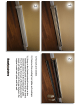
NOTE: This may require removing a section of baseboard
or other floor-level trim material and adjusting the levelers
under the wall stand.
CCS-UC-200-WSTND ONLY
Attaching the Wall Stand
Mount to the
wall through
the holes in
the three
wall stand
mounting
plates.
C. Attach the Tube Mount
Attach the tube mount to the wall stand as
shown below.
The tube mount is shown
in its upper position on
the bracket.
Mount with this
point facing up.
Attach using
four M10 nuts.
Remove four
screws before
reinstalling the
top cover.
NOTE: Ideal wall stand placement is in front of a power
outlet.

QUICKSTART DOC. 7787B (2043897) 08.15
2
quickstart guide
www.crestron.com
888.273.7876 201.767.3400
Specifications subject to
change without notice.
CCS-UC-200-WSTND ONLY
For regulatory compliance information, refer to Doc. 7599.
Wall Stand for 60", 70", and 80" Touch Displays
2
Assembly and Installation (Continued)
The specific patents that cover Crestron products are listed at patents.crestron.com.
Crestron, the Crestron logo, and Crestron RL are either trademarks or registered trademarks of
Crestron Electronics, Inc. in the United States and/or other countries. Lync is either a registered
trademark or trademark of Microsoft Corporation in the United States and/or other countries. Other
trademarks, registered trademarks, and trade names may be used in this document to refer to either
the entities claiming the marks and names or their products. Crestron disclaims proprietary interest in
the marks and names of others. Crestron is not responsible for errors in typography or photography.
This document was written by the Technical Publications department at Crestron.
©2015 Crestron Electronics, Inc.
CCS-UC-200-WSTND ONLY
D. Reinstall the Covers
Place all remaining hardware (except the tubes)
inside the wall stand. Place the top and bottom
covers on the wall stand, and use the locks to secure
them in position.
3
Overall Dimensions
29"
(737 mm)
~70-3/8"
(1788 mm)
~6-1/8"
(156 mm)
~8-5/8"
(219 mm)
/