3M Cold Shrink QT-III Termination Kit 7622-T-110, Tape/Wire/UniShield® Shielding, 5-15 kV, Insulation OD 0.64-1.08 in, 3/kit Operating instructions
- Type
- Operating instructions
This manual is also suitable for
- Cold Shrink QT-III Termination Kit 7624-T-110, Tape/Wire/UniShield® Shielding, 5-15 kV, Insulation OD 0.83-1.53 in, 3/kit
- Cold Shrink QT-III Termination Kit 7625-T-110, Tape/Wire/UniShield® Shielding, 5-15 kV, Insulation OD 1.05-1.80 in, 3/kit
- Cold Shrink QT-III Termination Kit 7626-T-110, Tape/Wire/UniShield® Shielding, 5-15 kV, Insulation OD 1.53-2.32 in, 3/kit

3M
™
Cold Shrink QT-III Silicone Rubber Indoor Tubular Termination Kit With High-K Stress Relief
3M
™
Cold Shrink QT-III Silicone Rubber Indoor
Tubular Termination Kit
With High-K Stress Relief
For Tape Shield, Wire Shield and UniShield
®
Cable
7622-T-110, 7622-T-110(L), 7623-T-110, 7624-T-110,
7625-T-110, 7625-T-110(L), 7626-T-110
Instructions
IEEE Std. No. 48
Class 1 Termination
15 kV Class
110 kV BIL
F CAUTION
Working around energized systems may cause serious injury or death. Installation should
be performed by personnel familiar with good safety practice in handling electrical
equipment. De-energize and ground all electrical systems before installing product.
February 2018
78-8113-5099-6 Rev G 3

2 78-8113-5099-6 Rev G
3M
™
Cold Shrink QT-III Silicone Rubber Indoor Tubular Termination Kit With High-K Stress Relief
1.0 Kit Contents
3 High–K, Tracking Resistant, Silicone Rubber Terminations
3 Pre-formed Ground Braids
3 Constant Force Springs
3 3M
™
EMI Copper Foil Shielding Tape 1181 Strips, 1/2" x 10"
6 Strips Scotch
®
Mastic Strip 2230 (black with white release liners, bagged)
1 3M
™
Cable Cleaning Preparation Kit CC-2
1 Instruction Sheet
Note: Do not use knives to open plastic bags.
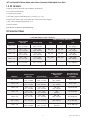
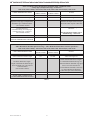
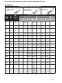
Kit Selection Tables
NOTE: Final Determination Factor is cable insulation diameter.
For Use With Compression Lugs or Connectors
Kit Number
Primary Insulation
O.D. Range Jacket O.D. Range
Conductor Size Range (AWG & kcmil)
5 kV 8 kV 15 kV
7622–T–110
0.64" – 1.08"
(16,3 – 27,4 mm)
0.97" – 1.48"
(24,6 – 37,7 mm)
4/0 – 400
—
3/0 – 300
—
2 – 2/0
(35 – 70 mm
2
)
7623–T–110
0.72" – 1.29"
(18,3 – 32,8 mm)
1.04" – 1.60"
(26,4 – 40,6 mm)
300 – 500
—
250 – 500
—
2/0 – 300
(70 – 150 mm
2
)
7624–T–110
0.83" – 1.53"
(21,1 – 38,9 mm)
1.12" – 1.87"
(28,4 – 47,5 mm)
500 – 750
—
350 – 700
—
4/0 – 500
(120 – 240 mm
2
)
7625–T–110
1.05" – 1.80"
(26,7 – 45,7 mm)
1.39" – 2.40"
(35,2 – 61,0 mm)
700 – 1500
—
600 – 1250
—
500 – 1000
(240 – 500 mm
2
)
7626–T–110
1.53" – 2.32"
(38,9 – 58,9 mm)
1.84" – 2.80"
(46,7 – 71,1 mm)
1750 – 2000
—
1500 – 2000
—
1250 – 2000
(625 – 1000 mm
2
)
Table 1
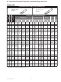
For Use With 3M™ Mechanical Shearbolt Lugs QL2 Series: Two Hole
Kit Number
Primary Insulation
O.D. Range Jacket O.D. Range
Conductor Size Range
(AWG & kcmil)
15 kV
3M™ Shearbolt Lugs
QL2 Series: Two Hole
Part Number
7622–T–110(L)
0.69" – 1.22"
(17,5 – 31,0 mm)
0.97" – 1.48"
(24,6 – 37,7 mm)
1/0 – 4/0
(60 – 120 mm
2
)
QL2–A–2–250
7623–T–110
0.72" – 1.29"
(18,3 – 32,8 mm)
1.04" – 1.60"
(26,4 – 40,6 mm)
2/0 – 250
(70 – 150 mm
2
)
QL2–A–2–250
7624–T–110
0.83" – 1.53"
(21,1 – 38,9 mm)
1.12" – 1.87"
(28,4 – 47,5 mm)
4/0 – 350
(120 – 150 mm
2
)
QL2–A–1/0–350
7625–T–110
1.05" – 1.80"
(26,7 – 45,7 mm)
1.39" – 2.40"
(35,2 – 61,0 mm)
500
(240 mm
2
)
QL2–A–4/0–600
7625–T–110
1.05" – 1.80"
(26,7 – 45,7 mm)
1.39" – 2.40"
(35,2 – 61,0 mm)
500 – 750
(240 – 325 mm
2
)
QL2–A–350–750
7625–T–110(L)
1.15" – 1.98"
(29,2 – 50,3 mm)
1.39" – 2.40"
(35,2 – 61,0 mm)
750 – 1000
(400 – 500 mm
2
)
QL2–A–500–1000
7626–T–110
1.53" – 2.32"
(38,9 – 58,9 mm)
1.84" – 2.80"
(46,7 – 71,1 mm)
1250
(625 mm
2
)
QL2–A–1000–1250
Table 2

78-8113-5099-6 Rev G 3
3M
™
Cold Shrink QT-III Silicone Rubber Indoor Tubular Termination Kit With High-K Stress Relief
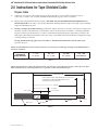
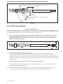
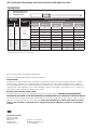
2.0 Instructions for Tape Shielded Cable
Prepare Cable
2.1 Check to be sure cable size fits within kit range as shown in Table 1. (For Use With Compression Lugs or
Connectors), or Table 2 (For Use With 3M Mechanical Shearbolt Lugs QL2 Series: Two Hole).
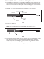
2.2 Prepare cable using dimensions shown in Figure 1. BE SURE TO ALLOW FOR DEPTH OF TERMINAL LUG
OR CONNECTOR. If necessary to prevent tape shield from unrolling, hold down edge with a single wrap of 3M EMI
Copper Foil Shielding Tape 1181.
2.3 If using a Crimp Type (Compression) lug, measure the depth of the barrel, or if using a Crimp Type (Compression)
connector, measure to the barrel center stop/midpoint, and see the NOTE below, and Table 3, concerning Aluminum
Lug and Connector growth allowances, in order to calculate the Insulation Removal Length. Table 6 (located in the
final pages of this Instruction document) can used to assist in calculating the total Jacket Removal Length when using
a compression lug or connector.
If using 3M Shearbolt Lugs QL2 Series: Two Hole, or 3M Mechanical Shearbolt Connector QCI Series,
proceed to Step 2.4.
NOTE: Provide additional exposed conductor distance to account for growth during crimping of ALUMINUM lugs or
connectors as follows:
Aluminum Lug
and Connector
Growth Allowance
2 - 350
1/4" (6 mm)
400 - 650
1/2" (13 mm)
750–1000
3/4" (19 mm)
1250 - 2000
Field determined
Table 3
NOTE: It is imperative to remove all remnants of the semi-con layer, even if the semi-con layer comes off as one layer.
There should not be any remaining black areas, or particles, on the cable insulation layer.
Jacket Removal Length
9" (229 mm)
3" (76 mm)
Semi-Con
Tape Shield
Insulation Removal Length = Depth Of Compression Lug or Connector
+ Growth Allowance OR InsulationCutback dimension from
Shearbolt Lug or Connector Instructions
1-1/2" (38 mm)
Cable Jacket
1-1/2" (38 mm)
Conductor
Insulation
Figure 1

4 78-8113-5099-6 Rev G
3M
™
Cold Shrink QT-III Silicone Rubber Indoor Tubular Termination Kit With High-K Stress Relief
2.4 If using 3M Mechanical Shearbolt Lugs QL2 Series: Two Hole, or 3M Mechanical Shearbolt Connector QCI Series,
refer to the Instructions that are packed with the Shearbolt product for the Insulation Cutback length for the specific
Shearbolt Lug or Connector being used. Table 7 (located in the final pages of this Instruction document) can used to
assist in calculating the total Jacket Removal Length when using 3M Shearbolt Lugs QL2 Series: Two Hole, or 3M
Shearbolt Connector QCI Series.
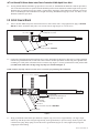
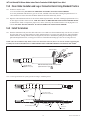
3.0 Install Ground Braid
3.1 Select a Scotch
®
Mastic Strip 2230 from kit and remove white release liners. Using light tension, apply a SINGLE
WRAP of mastic around the cable jacket 1/4" (6 mm) from cut edge (Figure 2). Cut off excess.
Semi-Con
Tape Shield
1st Scotch
®
Mastic Strip 2230 - SINGLE WRAP
Single Wrap of 3M
™
EMI Copper Foil
Shielding Tape 1181 (if used)
Cable Jacket
1/4" (6 mm)
Figure 2
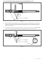
3.2 Position pre-formed ground braid with short tail over tape shield directly adjacent to cable jacket cut edge. PLEASE
NOTE: The ground braid needs to make full contact with the metallic tape shield. Position long tail of ground braid,
extending over cable jacket with solder block over mastic strip (Figure 3). Secure ground braid to cable jacket 4-1/2"
(114 mm) from cable semi-con edge using vinyl tape (see NOTE and Figure 3).
NOTE: Position vinyl tape with care, it also serves as a marker for positioning the termination.
Tape Shield
Ground Braid
Cable Jacket Edge
Vinyl Tape Marker
Semi-Con Edge
Solder Block
4-1/2" (114 mm)
1st Scotch
®
Mastic Strip 2230 - SINGLE WRAP
Single Wrap of 3M
™
EMI Copper Foil
Shielding Tape 1181 (if used)
Figure 3
3.3 Wrap ground braid around cable tape shield one complete wrap, trim excess at approximately a 45 degree angle,
and line up with the pre-bent 45 degree angle already on the ground braid, to prevent overlap. Secure in place with
constant force spring. Wrap spring in same direction as ground braid (Figure 4). Cinch (tighten) the spring after
wrapping the final winding.

78-8113-5099-6 Rev G 5
3M
™
Cold Shrink QT-III Silicone Rubber Indoor Tubular Termination Kit With High-K Stress Relief
3.4 Select second Scotch
®
Mastic Strip 2230 from kit and remove white release liners. Apply a second SINGLE WRAP
of mastic over solder block on ground braid and previously applied mastic (Figure 4). Cut off excess.
Tape Shield
Constant Force Spring
Ground Braid
Solder Block
Ground Braid Leg
Trim
Cable
Tape
Shield
1st Scotch
®
Mastic Strip 2230 - SINGLE WRAP
2nd Scotch
®
Mastic Strip 2230 - SINGLE WRAP
Single Wrap of 3M
™
EMI Copper Foil Shielding Tape 1181 (if used)
Figure 4
3.5 Wrap two highly stretched half-lapped layers of electrical grade vinyl tape around Scotch
®
Mastic Strip 2230,
constant force spring and exposed tape shield (Figure 5).
NOTE: Take care not to cover exposed semi-con insulation shield. A minimum of 1" (25 mm) must be exposed.
NOTE: DO NOT completely cover the ground braid with electrical grade vinyl tape when applying over the Scotch
®
Mastic Strip 2230 per Step 3.5. LEAVE A MINIMUM OF 1/4" (6 MM) OF EXPOSED GROUND BRAID between the
Vinyl Tape Marker applied in step 3.2 and the start of the two half-lapped layers of electrical grade vinyl tape covering
the Scotch
®
Mastic Strip 2230 applied in Step 3.5.
SPECIAL NOTE FOR CLOTH OR PAPER SEMI-CON INSULATION SHIELD
In cables with cloth or paper semi-conductive shields, it is recommended the shield be over wrapped with one half-
lapped layer of highly stretched semi-conductive rubber tape, such as Scotch
®
Electrical Semi-Conducting Tape 13.
Semi-Con (Must Leave Minimum of 1" (25 mm) Exposed. See Note Under Step 3.5.)
Constant Force Spring
Two Highly Stretched Half-Lapped Layers of Electrical Grade Vinyl Tape
Tape Shield Ground Braid
Scotch
®
Mastic Strip 2230
Vinyl Tape Marker
Ground Braid (Must Leave Minimum of 1/4" (6 MM) Exposed. See Note Under Step 3.5.)
Figure 5

6 78-8113-5099-6 Rev G
3M
™
Cold Shrink QT-III Silicone Rubber Indoor Tubular Termination Kit With High-K Stress Relief
4.0 Install Lug or Connector
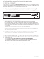
Important Packaging Notice
In order to make sure that you receive an undamaged termination, this 3M Cold Shrink QT-III Silicone Rubber Termination
is packed with a RED SHIPPING CORE inside of the white core. Please remove the red shipping core BEFORE you install
the termination. This shipping core can be recycled with other polypropylene waste.
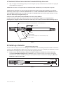
4.1 Check to insure 3M Cold Shrink QT-lll Silicone Rubber Termination assembly fits over the selected lug
or connector BEFORE installing the lug or connector. If lug or connector. (Figure 6) will not fit through the
termination core, clean the insulation (per Step 5.0) and slide termination on cable before installing lug or connector.
DO NOT REMOVE CORE AT THIS TIME.
Clearance
Connector/Lug
Figure 6
4.2 For 3M Compression Lugs and 3M Stem Connectors:
a. Refer to the final pages of this Instruction document for 3M Connector and Lug crimping information.
b. For Aluminum Conductors - Thoroughly wire brush conductor strands to remove aluminum oxide layer. Insert
conductor into lug or connector and then remove conductor. This will transfer some of the antioxidant paste onto the
conductor. Wire brush the antioxidant paste into the strands. Immediately insert conductor into lug or connector barrel
as far as it will go.
NOTE: Die/crimper head rotation between consecutive crimps is RECOMMENDED.
c. Position connector or lug and crimp according to manufacturer's directions. Remove excess oxide inhibitor and
sharp crimp flashings following crimping.
4.3 For 3M Mechanical Shearbolt Lugs QL2 Series: Two Hole or 3M Mechanical Shearbolt Connector QCI Series:
a. Refer to the Instructions that are packed with the Shearbolt product for the installation procedures.
5.0 Clean Cable Insulation and Lug or Connector Barrel Using Standard Practice
5.1 If abrasive must be used:
a. Use on insulation only. DO NOT USE ABRASIVE ON SEMI-CON INSULATION SHIELD!
b. Use only aluminum oxide abrasive; grit 120 or finer, included in 3M Cable Cleaning Preparation Kit CC-2.
c. Be careful not to reduce the cable insulation diameter below that allowed by the kit.
5.2 Wipe the cable insulation with one of the solvent saturated pads from the 3M Cable Cleaning Preparation Kit CC-2,
or other approved cable cleaner/solvent, AND ALLOW IT TO DRY BEFORE INSTALLING TERMINATION.
A clean lint-free cloth, or inexpensive paper towel, can be used to dry the insulation surface if air drying time is of
concern. DO NOT ALLOW SOLVENT TO TOUCH SEMI-CON INSULATION SHIELD!

78-8113-5099-6 Rev G 7
3M
™
Cold Shrink QT-III Silicone Rubber Indoor Tubular Termination Kit With High-K Stress Relief
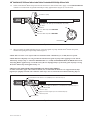
6.0 Install Termination
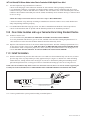
6.1 Slide the termination body onto the cable and remove core. Make sure the termination body (not the core) is butted
up to the edge of the vinyl tape marker previously applied in Step 3.2 (Figure 7). Pull the core while unwinding,
counterclockwise, starting with the loose end (Figure 7). Be sure to alternate the pulling and unwinding actions
(pull-unwind-pull-unwind-etc.) to help prevent the core material from binding up as the core is being removed.
NOTE: Once the termination body makes contact over the mastic seal area, there is no need to continue supporting the
assembly. DO NOT PUSH OR PULL ON THE TERMINATION ASSEMBLY WHILE UNWINDING THE CORE.
Vinyl Tape Marker
(Applied in Step 3.2)
Counterclockwise
NOTE: The material being removed at this step is mixed polymers
and can be recycled.
Figure 7
6.2 Connect ground braid to system ground according to standard practice.
Semi-Con Insulation Shield
Ridge at End of Cable
Insulation Shield (Semi-Con)
Ridge at End
of High-K Tube
Correct Installation of Termination on Tape Shielded Cable
Cable Insulation
Conductor
Vinyl Tape
Marker
Environmental Top
Seal
Stress Controlling Compound
High-K Stress
Relief Tube

8 78-8113-5099-6 Rev G
3M
™
Cold Shrink QT-III Silicone Rubber Indoor Tubular Termination Kit With High-K Stress Relief
Instructions for Wire Shielded Cable
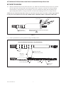
7.0 Prepare Cable
7.1 Check to be sure cable size fits within kit range as shown in Table 1. (For Use With Compression Lugs or
Connectors), or Table 2 (For Use With 3M Mechanical Shearbolt Lugs QL2 Series: Two Hole).
7.2 Prepare cable using dimensions shown in Figure 8 and Figure 9. BE SURE TO ALLOW FOR DEPTH OF
TERMINAL LUG OR CONNECTOR.
7.3 If using a Crimp Type (Compression) lug, measure the depth of the barrel, or if using a Crimp Type (Compression)
connector, measure to the barrel center stop/midpoint, and see the NOTE below, and Table 4, concerning Aluminum
Lug and Connector growth allowances, in order to calculate the Insulation Removal Length. Table 8 (located in the
final pages of this Instruction document) can used to assist in calculating the total Jacket Removal Length when using
a compression lug or connector.
If using 3M Shearbolt Lugs QL2 Series: Two Hole, or 3M Mechanical Shearbolt Connector QCI Series,
proceed to Step 7.4.
NOTE: Provide additional exposed conductor distance to account for growth during crimping of ALUMINUM lugs or
connectors as follows:
Aluminum Lug
and Connector
Growth Allowance
2 - 350
1/4" (6 mm)
400 - 650
1/2" (13 mm)
750–1000
3/4" (19 mm)
1250 - 2000
Field determined
Table 4
NOTE: It is imperative to remove all remnants of the semi-con layer, even if the semi-con layer comes off as one layer.
There should not be any remaining black areas, or particles, on the cable insulation layer.
9" (229 mm)
Insulation Removal Length = Depth Of Compression Lug or Connector
+ Growth Allowance OR Insulation Cutback dimension from
Shearbolt Lug or Connector Instructions
3" (76 mm)
Jacket Removal Length
Semi-Con
Shield Wires
Cable Jacket
Insulation
Conductor
Figure 8

78-8113-5099-6 Rev G 9
3M
™
Cold Shrink QT-III Silicone Rubber Indoor Tubular Termination Kit With High-K Stress Relief
7.4 If using 3M Mechanical Shearbolt Lugs QL2 Series: Two Hole, or 3M Mechanical Shearbolt Connector QCI Series,
refer to the Instructions that are packed with the Shearbolt product for the Insulation Cutback length for the specific
Shearbolt Lug or Connector being used. Table 9 (located in the final pages of this Instruction document) can used to
assist in calculating the total Jacket Removal Length when using 3M Shearbolt Lugs QL2 Series: Two Hole, or 3M
Shearbolt Connector QCI Series.
7.5 Bend leading 1-1/2" (38 mm) of exposed shield wires back upon themselves to jacket edge (Figure 9).
3" (76 mm)
1-1/2" (38 mm)
Semi-Con
Shield Wires
Cable Jacket
1-1/2" (38 mm)
Figure 9
8.0 Install Ground Braid
8.1 Select a Scotch
®
Mastic Strip 2230 from kit and remove white release liners. Using light tension apply a SINGLE
WRAP of mastic around the cable jacket 1/4" (6 mm) from cut edge (Figure 10). Cut off excess.
Semi-Con
Cable Jacket
1/4" (6 mm)
1st Scotch
®
Mastic Strip 2230 - SINGLE WRAP
Figure 10
8.2 Position pre-formed ground braid with short tail over wire shield directly adjacent to cable jacket cut edge. PLEASE
NOTE: The ground braid needs to make full contact with the shield wires. Position long tail of ground braid,
extending over cable jacket with solder block over mastic strip (Figure 11). Secure ground braid to cable jacket
4-1/2" (114 mm) from cable semi-con edge using vinyl tape (see NOTE and Figure 11).
NOTE: Position vinyl tape with care, it also serves as a marker for positioning the termination.

10 78-8113-5099-6 Rev G
3M
™
Cold Shrink QT-III Silicone Rubber Indoor Tubular Termination Kit With High-K Stress Relief
Shield Wire
Ground Braid
Cable Jacket Edge
Vinyl Tape Marker
Semi-Con Edge
Solder Block
4-1/2" (114 mm)
1st Scotch
®
Mastic Strip 2230 - SINGLE WRAP
Figure 11
8.3 Wrap ground braid around cable shield wires one complete wrap, trim excess at approximately a 45 degree angle,
and line up with the pre-bent 45 degree angle already on the ground braid, to prevent overlap. Secure in place with
constant force spring. Wrap spring in same direction as ground braid (Figure 12). Cinch (tighten) the spring after
wrapping the final winding.
8.4 Select second Scotch
®
Mastic Strip 2230 from kit and remove white release liners. Apply a second SINGLE WRAP
of mastic over solder block on ground braid and previously applied mastic (Figure 12). Cut off excess.
Shield Wires
Constant Force Spring
Ground Braid
Solder Block
Ground Braid Leg
Trim
Cable
Wire
Shield
1st Scotch
®
Mastic Strip 2230 - SINGLE WRAP
2nd Scotch
®
Mastic Strip 2230 - SINGLE WRAP
Figure 12

78-8113-5099-6 Rev G 11
3M
™
Cold Shrink QT-III Silicone Rubber Indoor Tubular Termination Kit With High-K Stress Relief
8.5 Wrap two highly stretched half-lapped layers of electrical grade vinyl tape around mastic seal, constant force spring and
exposed shield wires (Figure 13).
NOTE: Take care not to cover exposed semi-con insulation shield. A minimum of 1" (25 mm) must be exposed.
NOTE: DO NOT completely cover the ground braid with electrical grade vinyl tape when applying over the Scotch
®
Mastic Strip 2230 per Step 8.5. LEAVE A MINIMUM OF 1/4" (6 MM) OF EXPOSED GROUND BRAID between the
Vinyl Tape Marker applied in step 8.2 and the start of the two half-lapped layers of electrical grade vinyl tape covering
the Scotch
®
Mastic Strip 2230 applied in Step 8.5.
SPECIAL NOTE FOR CLOTH OR PAPER SEMI-CON INSULATION SHIELD
In cables with cloth or paper semi-conductive shields, it is recommended the shield be over-wrapped with one
half-lapped layer of highly stretched semi-conductive rubber tape, such as Scotch
®
Electrical Semi-Conducting Tape 13.
Semi-Con (Note: A minimum of 1" (25 mm) must be exposed. See NOTE under 8.5.)
Constant Force Spring
Two Highly Stretched Half-Lapped Layers of Electrical Grade Vinyl Tape
Shield Wires
Vinyl Tape Marker
1-1/2" (38 mm)
Scotch
®
Mastic Strip 2230
Ground Braid (Must Leave Minimum of 1/4" (6 MM) Exposed. See Note Under Step 8.5.)
Figure 13
9.0 Install Lug or Connector
Important Packaging Notice
In order to make sure that you receive an undamaged termination, this 3M Cold Shrink QT-III Silicone Rubber Termination
is packed with a RED SHIPPING CORE inside of the white core. Please remove the red shipping core BEFORE you install
the termination. This shipping core can be recycled with other polypropylene waste.
9.1 Check to insure 3M Cold Shrink QT-III Silicone Rubber Termination assembly fits over the selected lug
or connector BEFORE installing the lug or connector. If lug or connector (Figure 14) will not fit through the
termination core, clean the insulation (per Step 10.0) and slide termination on cable before installing lug. DO NOT
REMOVE CORE AT THIS TIME.
Clearance
Connector/Lug
Figure 14

12 78-8113-5099-6 Rev G
3M
™
Cold Shrink QT-III Silicone Rubber Indoor Tubular Termination Kit With High-K Stress Relief
9.2 For 3M Compression Lugs and 3M Stem Connectors:
a. Refer to the final pages of this instruction document for 3M Connector and Lug crimping information.
b. For Aluminum Conductors - Thoroughly wire brush conductor strands to remove aluminum oxide layer. Insert
conductor into lug or connector and then remove conductor. This will transfer some of the antioxidant paste onto the
conductor. Wire brush the antioxidant paste into the strands. Immediately insert conductor into lug or connector barrel
as far as it will go.
NOTE: Die/crimper head rotation between consecutive crimps is RECOMMENDED.
c. Position connector or lug and crimp according to manufacturer's directions. Remove excess oxide inhibitor and
sharp crimp flashings following crimping.
9.3 For 3M Mechanical Shearbolt Lugs QL2 Series: Two Hole or 3M Mechanical Shearbolt Connector QCI Series:
a. Refer to the Instructions that are packed with the Shearbolt product for the installation procedures.
10.0 Clean Cable Insulation and Lug or Connector Barrel Using Standard Practice
10.1 If abrasive must be used:
a. Use on insulation only. DO NOT USE ABRASIVE ON SEMI-CON INSULATION SHIELD!
b. Use only aluminum oxide abrasive; grit 120 or finer, included in the 3M Cable Cleaning Preparation Kit CC-2.
c. Be careful not to reduce the cable insulation diameter below that allowed by the kit.
10.2 Wipe the cable insulation with one of the solvent saturated pads from the 3M Cable Cleaning Preparation Kit CC-2,
or other approved cable cleaner/solvent, AND ALLOW IT TO DRY BEFORE INSTALLING TERMINATION.
A clean lint-free cloth, or inexpensive paper towel, can be used to dry the insulation surface if air drying time is of
concern. DO NOT ALLOW SOLVENT TO TOUCH SEMI-CON INSULATION SHIELD!
11.0 Install Termination
11.1 Slide the termination body onto the cable and remove core. Make sure the termination body (not the core) is butted
up to the edge of the vinyl tape marker previously applied in Step 8.2 (Figure 15). Pull the core while unwinding,
counterclockwise, starting with the loose end (Figure 15). Be sure to alternate the pulling and unwinding actions
(pull-unwind-pull-unwind-etc.) to help prevent the core material from binding up as the core is being removed.
NOTE: Once the termination body makes contact over the mastic seal area, there is no need to continue supporting the
assembly. DO NOT PUSH OR PULL ON THE TERMINATION ASSEMBLY WHILE UNWINDING THE CORE.
Vinyl Tape Marker
(Applied in Step 8.2)
Counterclockwise
NOTE: The material being removed at this step is mixed
polymers and can be recycled.
Figure 15
11.2 Connect ground braid to system ground according to standard practice.

78-8113-5099-6 Rev G 13
3M
™
Cold Shrink QT-III Silicone Rubber Indoor Tubular Termination Kit With High-K Stress Relief
Semi-Con Insulation Shield
Ridge at End of Cable
Insulation Shield (Semi-Con)
Ridge at End
of High-K Tube
Correct Installation of Termination on Wire Shielded Cable
Cable Insulation
Conductor
Vinyl Tape
Marker
Seal
Stress Controlling Compound
High-K Stress
Relief Tube
Environmental Top
Instructions for UniShield
®
Cable
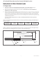
12.0 Prepare Cable
12.1 Check to be sure cable size fits within kit range as shown in Table 1 (For Use With Compression Lugs or
Connectors), or Table 2 (For Use With 3M Mechanical Shearbolt Lugs QL2 Series: Two Hole).
12.2 Prepare cable using dimensions shown in Figures 16, 17 and 18. BE SURE TO ALLOW FOR DEPTH OF
TERMINAL LUG OR CONNECTOR.
12.3 If using a Crimp Type (Compression) lug, measure the depth of the barrel, or if using a Crimp Type (Compression)
connector, measure to the barrel center stop/midpoint, and see the NOTE below, and Table 5, concerning Aluminum
Lug and Connector growth allowances, in order to calculate the Insulation Removal Length. Table 10 (located in the
final pages of this Instruction document) can used to assist in calculating the total Jacket Removal Length when using
a compression lug or connector.
If using 3M Shearbolt Lugs QL2 Series: Two Hole, or 3M Mechanical Shearbolt Connector QCI Series,
proceed to Step 12.5.
12.4 Install constant force spring as shown in Figure 16. Pull shield wires through semi-conductive jacket to leading edge
of constant force spring (Figure 16).
NOTE: Provide additional exposed conductor distance to account for growth during crimping of ALUMINUM lugs
or connectors as follows:
Aluminum Lug
and Connector
Growth Allowance
2 - 350
1/4” (6 mm)
400 - 650
1/2” (13 mm)
750–1000
3/4” (19 mm)
1250 - 2000
Field determined
Table 5

14 78-8113-5099-6 Rev G
3M
™
Cold Shrink QT-III Silicone Rubber Indoor Tubular Termination Kit With High-K Stress Relief
Insulation Removal Length = Depth Of Compression Lug or Connector
+ Growth Allowance OR Insulation Cutback dimension from
Shearbolt Lug or Connector Instructions
7-1/2" (191 mm)
Semi-Conductive Jacket
Constant Force Spring
Shield Wires
Figure 16
12.5 If using 3M Mechanical Shearbolt Lugs QL2 Series: Two Hole, or 3M Mechanical Shearbolt Connector QCI Series,
refer to the Instructions that are packed with the Shearbolt product for the Insulation Cutback length for the specific
Shearbolt Lug or Connector being used. Table 11 (located in the final pages of this Instruction document) can used to
assist in calculating the total Semi-Conductive Jacket Removal Length when using 3M Shearbolt Lugs QL2 Series:
Two Hole, or 3M Shearbolt Connector QCI Series.
12.6 Remove constant force spring. Bend shield wires back upon semi-conductive jacket 1-1/2" (38 mm). Cut excess
shield wire and discard (Figure 17).
9" (229 mm)
1-1/2" (38 mm)
Semi-Conductive Jacket
Shield Wires Bent Back Over Semi-Conductive Jacket
Insulation Removal Length = Depth Of Compression Lug or Connector
+ Growth Allowance OR Insulation Cutback dimension from
Shearbolt Lug or Connector Instructions
Figure 17
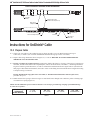
12.7 Remove semi-conductive jacket to dimension shown in Figure 18.
NOTE: To ease jacket removal, install constant force spring as shown in Figure 18 and ring-cut 80% through jacket.
Remove jacket sections by pulling against constant force spring. DO NOT BELL SEMI-CON JACKET. Remove
constant force spring.
NOTE: It is imperative to remove all remnants of the semi-conductive jacket, even if the semi-conductive jacket comes
off as one layer. There should not be any remaining black areas, or particles, on the cable insulation layer.

78-8113-5099-6 Rev G 15
3M
™
Cold Shrink QT-III Silicone Rubber Indoor Tubular Termination Kit With High-K Stress Relief
Insulation Removal Length = Depth Of Compression Lug or Connector
+ Growth Allowance OR Insulation Cutback dimension from
Shearbolt Lug or Connector Instructions
6" (152 mm)
1-1/2"
(38 mm)
Semi-Conductive Jacket
Cut Line
Constant Force Spring
Shield Wires Bent Back Over Semi-Conductive Jacket
1-1/2" (38 mm)
Conductor
Figure 18
13.0 Install Ground Braid
13.1 Select a Scotch
®
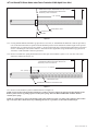
Mastic Strip 2230 from kit and remove white release liners. Using light tension apply a SINGLE
WRAP of mastic around the cable semi-conductive jacket 1/4" (6 mm) from shield wires (Figure 19). Cut
off excess.
Semi-Conductive Jacket
Shield Wires Bent Back Over Semi-Conductive Jacket
1/4" (6 mm)
1st Scotch
®
Mastic Strip 2230 - SINGLE WRAP
Figure 19
13.2 Position pre-formed ground braid with short tail directly over cut edge of folded back shield wires. PLEASE NOTE:
The ground braid needs to make full contact with the shield wires. Position long tail of ground braid, extending over
cable semi-conductive jacket with solder block over mastic strip (Figure 20). Secure ground braid to cable semi-
conductive jacket 4-1/2" (114 mm) from cable Semi-Conductive Jacket edge using vinyl tape (See NOTE and
Figure 20).
NOTE: Position vinyl tape with care, it also serves as a marker for positioning the termination.

16 78-8113-5099-6 Rev G
3M
™
Cold Shrink QT-III Silicone Rubber Indoor Tubular Termination Kit With High-K Stress Relief
Shield Wire
Ground Braid
Solder Block
Semi-Conductive Jacket Edge
Vinyl Tape Marker
4-1/2" (114 mm)
1st Scotch
®
Mastic Strip 2230 - SINGLE WRAP
Figure 20
13.3 Wrap ground braid around cable shield wires one complete wrap, trim excess at approximately a 45 degree angle,
and line up with the pre-bent 45 degree angle already on the ground braid, to prevent overlap. Secure in place with
constant force spring. Wrap spring in same direction as ground braid (Figure 21). Cinch (tighten) the spring after
wrapping the final winding.
13.4 Select second Scotch
®
Mastic Strip 2230 from kit and remove white release liners. Apply a second SINGLE WRAP
of mastic over solder block on ground braid and previously applied mastic (Figure 21). Cut off excess.
Shield Wires
Constant Force Spring
Ground Braid
Solder Block
Ground Braid Leg
Trim
Cable
Wire
Shield
1st Scotch
®
Mastic Strip 2230 - SINGLE WRAP
2nd Scotch
®
Mastic Strip 2230 - SINGLE WRAP
Figure 21
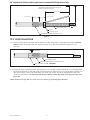
13.5 Wrap two highly stretched half-lapped layers of electrical grade vinyl tape around mastic seal, constant force spring
and exposed shield wires (Figure 22).
NOTE: Take care not to cover exposed Semi-Conductive Jacket. A minimum of 1" (25 mm) must be exposed.
NOTE: DO NOT completely cover the ground braid with electrical grade vinyl tape when applying over the Scotch
®
Mastic Strip 2230 per Step 13.5. LEAVE A MINIMUM OF 1/4" (6 MM)OF EXPOSED GROUND BRAID between the
Vinyl Tape Marker applied in step 13.2 and the start of the two half-lapped layers of electrical grade vinyl tape covering
the Scotch
®
Mastic Strip 2230 applied in Step 13.5.

78-8113-5099-6 Rev G 17
3M
™
Cold Shrink QT-III Silicone Rubber Indoor Tubular Termination Kit With High-K Stress Relief
Semi-Conductive Jacket (NOTE: A minimum of 1" (25 mm) must be exposed.)
Constant Force Spring
Two Highly Stretched Half-Lapped Layers of Electrical Grade Vinyl Tape
Shield Wires
Vinyl Tape Marker
1-1/2" (38 mm)
Scotch
®
Mastic Strip 2230
Ground Braid (Must Leave Minimum of 1/4" (6 MM) Exposed. See Note Under Step 13.5.)
Figure 22
14.0 Install Lug or Connector
Important Packaging Notice
In order to make sure that you receive an undamaged termination, this 3M Cold Shrink QT-III Silicone Rubber Termination
is packed with a RED SHIPPING CORE inside of the white core. Please remove the red shipping core BEFORE you install
the termination. This shipping core can be recycled with other polypropylene waste.
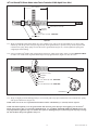
14.1 Check to insure 3M Cold Shrink QT -III Silicone Rubber Termination fits over the selected lug or connector
BEFORE installing the lug or connector. If lug or connector (Figure 23) will not fit through the termination core,
clean the insulation (per Step 15.0) and slide termination on cable before installing lug or connector. DO NOT
REMOVE CORE AT THIS TIME.
Clearance
Connector/Lug
Figure 23
14.2 For 3M Compression Lugs and 3M Stem Connectors:
a. Refer to the final pages of this Instruction document for 3M Connector and Lug crimping information.
b. For Aluminum Conductors - Thoroughly wire brush conductor strands to remove aluminum oxide layer. Insert
conductor into lug or connector and then remove conductor. This will transfer some of the antioxidant paste onto the
conductor. Wire brush the antioxidant paste into the strands. Immediately insert conductor into lug or connector barrel
as far as it will go.
NOTE: Die/crimper head rotation between consecutive crimps is Recommended.
c. Position connector or lug and crimp according to manufacturer's directions. Remove excess oxide inhibitor and
sharp crimp flashings following crimping.
14.3 For 3M Mechanical Shearbolt Lugs QL2 Series: Two Hole or 3M Mechanical Shearbolt Connector QCI Series:
a. Refer to the Instructions that are packed with the Shearbolt product for the installation procedures.

18 78-8113-5099-6 Rev G
3M
™
Cold Shrink QT-III Silicone Rubber Indoor Tubular Termination Kit With High-K Stress Relief
15.0 Clean Cable Insulation and Lug or Connector Barrel Using Standard Practice
15.1 If abrasive must be used:
a. Use on insulation only. DO NOT USE ABRASIVE ON SEMI-CON INSULATION SHIELD!
b. Use only aluminum oxide abrasive; grit 120 or finer, included in the 3M Cable Cleaning Preparation Kit CC-2.
c. Be careful not to reduce the cable insulation diameter below that allowed by the kit.
15.2 Wipe the cable insulation with one of the solvent saturated pads from the 3M Cable Cleaning Preparation Kit CC-2,
or other approved cable cleaner/solvent, AND ALLOW IT TO DRY BEFORE INSTALLING TERMINATION.
A clean lint-free cloth, or inexpensive paper towel, can be used to dry the insulation surface if air drying time is of
concern. DO NOT ALLOW SOLVENT TO TOUCH SEMI-CON INSULATION SHIELD!
16.0 Install Termination
16.1 Slide the termination body onto the cable and remove core. Make sure the termination body (not the core) is butted
up to the edge of the vinyl tape marker previously applied in Step 13.2 (Figure 24). Pull the core while unwinding,
counterclockwise, starting with the loose end (Figure 24). Be sure to alternate the pulling and unwinding actions
(pull-unwind-pull-unwind-etc.) to help prevent the core material from binding up as the core is being removed.
NOTE: Once the termination body makes contact over the mastic seal area, there is no need to continue supporting the
assembly. DO NOT PUSH OR PULL ON THE TERMINATION ASSEMBLY WHILE UNWINDING THE CORE.
Vinyl Tape Marker
(Applied in Step 13.2)
Counterclockwise
NOTE: The material being removed at this step is mixed
polymers and can be recycled.
Figure 24
16.2 Connect ground braid to system ground according to standard practice.
Semi-Con
Ridge at End of Cable
Insulation Shield (Semi-Con)
Ridge at End
of High-K Tube
Correct Installation of Termination on UniShield
®
Shielded Cable
Cable Insulation
Conductor
Vinyl Tape
Marker
Seal
Stress Controlling Compound
High-K Stress
Relief Tube
Environmental Top

78-8113-5099-6 Rev G 19
3M
™
Cold Shrink QT-III Silicone Rubber Indoor Tubular Termination Kit With High-K Stress Relief
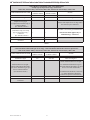
Jacket Removal Calculation Table - Tape Shield Cable
- Crimp Type (Compression) Lugs / Connectors -
7622-T-110, 7622-T-110(L), 7623-T-110, 7624-T-110, 7625-T-110, 7625-T-110(L), 7626-T-110
CABLE PREPARATION ITEM
Inches
-Add this column-
mm
-Add this column-
NOTES
Insulation Length
9.0" 229 mm Value from Figure 1
Insulation Removal Length =
Depth of Crimp Type
(Compression) Terminal Lug or
Connector Barrel
(See NOTES column.)
+ +
Measure full depth of bore for lugs and to
the center stop for connectors.
Growth Allowance
(Aluminum Only) for Crimp
Type (Compression) Lug /
Connector
(See NOTES column.)
+ +
See Table 3 for correct growth allowance.
This measurement applies only to
Aluminum lugs / connectors.
TOTAL JACKET REMOVAL
LENGTH
= =
Table 6
Jacket Removal Calculation Table - Tape Shield Cable
- 3M™ Mechanical Shearbolt QL2 Series Lugs / 3M™ Mechanical Shearbolt Connectors QCI Series -
7622-T-110, 7622-T-110(L), 7623-T-110, 7624-T-110, 7625-T-110, 7625-T-110(L), 7626-T-110
CABLE PREPARATION ITEM
Inches
-Add this column-
mm
-Add this column-
NOTES
Insulation Length 9.0" 229 mm Value from Figure 1
Insulation Removal Length =
Depth of Mechanical Shearbolt
QL2 Series Terminal Lug or QCI
Series Connector Barrel
(See NOTES column.)
+ +
Obtain Insulation Removal Length:
For Mechanical Shearbolt Lugs see
3M™ Mechanical Shearbolt Lugs QL2
Series: Two Hole Instructions.
For Mechanical Shearbolt Connectors
see 3M™ Mechanical Shearbolt
Connectors QCI Series Instructions.
TOTAL JACKET REMOVAL
LENGTH
= =
Table 7

20 78-8113-5099-6 Rev G
3M
™
Cold Shrink QT-III Silicone Rubber Indoor Tubular Termination Kit With High-K Stress Relief
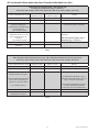
Jacket Removal Calculation Table - Wire Shield Cable
- Crimp Type (Compression) Lugs / Connectors -
7622-T-110, 7622-T-110(L), 7623-T-110, 7624-T-110, 7625-T-110, 7625-T-110(L), 7626-T-110
CABLE PREPARATION ITEM
Inches
-Add this column-
mm
-Add this column-
NOTES
Insulation Length 9.0" 229 mm Value from Figure 8
Insulation Removal Length =
Depth of Crimp Type
(Compression) Terminal Lug or
Connector Barrel
(See NOTES column.)
+ +
Measure full depth of bore for lugs and
to the center stop for connectors.
Growth Allowance
(Aluminum Only) for Crimp
Type (Compression) Lug /
Connector
(See NOTES column.)
+ +
See Table 4 for correct growth
allowance.
This measurement applies only to
Aluminum lugs / connectors.
TOTAL JACKET REMOVAL
LENGTH
= =
Table 8
Jacket Removal Calculation Table - Wire Shield Cable
- 3M™ Mechanical Shearbolt QL2 Series Lugs / 3M™ Mechanical Shearbolt Connector QCI Series -
7622-T-110, 7622-T-110(L), 7623-T-110, 7624-T-110, 7625-T-110, 7625-T-110(L), 7626-T-110
CABLE PREPARATION ITEM
Inches
-Add this column-
mm
-Add this column-
NOTES
Insulation Length 9.0" 229 mm Value from Figure 8
Insulation Removal Length =
Depth of Mechanical Shearbolt
QL2 Series Terminal Lug or
QCI Series Connector Barrel
(See NOTES column.)
+ +
Obtain Insulation Removal Length:
For Mechanical Shearbolt Lugs see
3M™ Mechanical Shearbolt Lugs QL2
Series: Two Hole Instructions.
For Mechanical Shearbolt Connectors
see 3M™ Mechanical Shearbolt
Connectors QCI Series Instructions.
TOTAL SEMI-CON JACKET
REMOVAL LENGTH
= =
Table 9
Page is loading ...
Page is loading ...
Page is loading ...
Page is loading ...
-
 1
1
-
 2
2
-
 3
3
-
 4
4
-
 5
5
-
 6
6
-
 7
7
-
 8
8
-
 9
9
-
 10
10
-
 11
11
-
 12
12
-
 13
13
-
 14
14
-
 15
15
-
 16
16
-
 17
17
-
 18
18
-
 19
19
-
 20
20
-
 21
21
-
 22
22
-
 23
23
-
 24
24


3M Cold Shrink QT-III Termination Kit 7622-T-110, Tape/Wire/UniShield® Shielding, 5-15 kV, Insulation OD 0.64-1.08 in, 3/kit Operating instructions
- Type
- Operating instructions
- This manual is also suitable for
-
- Cold Shrink QT-III Termination Kit 7624-T-110, Tape/Wire/UniShield® Shielding, 5-15 kV, Insulation OD 0.83-1.53 in, 3/kit
- Cold Shrink QT-III Termination Kit 7625-T-110, Tape/Wire/UniShield® Shielding, 5-15 kV, Insulation OD 1.05-1.80 in, 3/kit
- Cold Shrink QT-III Termination Kit 7626-T-110, Tape/Wire/UniShield® Shielding, 5-15 kV, Insulation OD 1.53-2.32 in, 3/kit
Ask a question and I''ll find the answer in the document
Finding information in a document is now easier with AI
Related papers
-
3M Cold Shrink QT-II Outdoor Termination Kit 5691K, 15-25/28 kV, 0.64-0.90 in (16,3-22,9 mm) Cable Insul. O.D., 3/kit Operating instructions
-
-
-
-
-
-
-
-
3M 2120-EP User manual
-
Other documents
-
 Pittsburgh Coaxial Cable Compression Tool Owner's manual
-
 Pittsburgh Item 57195 Owner's manual
-
AlumiConn 95035 Installation guide
-
 Burndy Y122CMR Installation guide
-
Catamount TT-14-30-0-L Specification
-
Hubbell IS-200TW Installation guide
-
 Burndy Y1MRTC Installation guide
-
Chromalox RG-PK Installation guide
-
WarmlyYours Snow Melt and Slab Heat Repair Kit Operating instructions
-
 Hubbell Power Systems IS635BT Operating instructions


