
Model: ASG-TP50BCS
This snow protection hood prevents snow from entering the outdoor unit and prevents strong winds from
blowing against the heat exchanger. Be sure to read this manual carefully for correct performance before
installation work.
Installation Manual for Snow Protection Hood (for Outdoor Unit)
: Indicates a hazardous situation that, if not avoided,
could result in death or serious injury.
: Indicates a hazardous situation that, if not avoided,
could result in minor or moderate injury.
1. Applicable Unit
Name Hood for Rear Side Air Inlet
Model ASG-TP50BCS
Applicable Outdoor Unit
(Representative Model)
(H,Y)VAHP168, 192B32S
(H,Y)VAHP168, 192B42S
NOTICE:
The applicable outdoor unit may be different depending on the product series. Be sure to conrm with the
product catalogue before installation.
2. Installation Work
(1) After the snow protection hood is installed, noise at the air outlet side may slightly increase. Consider
carefully the air discharge direction when installing.
(2) Tighten the snow protection hood securely to the top panel and side panel of the outdoor unit with the
supplied screws (accessories). Not doing so may cause vibration or abnormal noise.
(3) Avoid obstacles in the direction of air discharge from the snow protection hood to prevent short circuit
or a reduction in the airow rate.
(4) Do not install other outdoor units in the direction of the air outlet. If the air blown out of the snow
protection hood is sucked into the other outdoor unit, it may cause a malfunction of the unit.
(5) Double-check the strength of the anchor bolts of the outdoor unit. The wind loads on the outdoor unit
change by attaching the snow protection hood. The required installation strength also changes in
strong wind.
(6) After installing the snow protection hood, cooling/heating performance may be slightly affected
depending on usage.
IMPORTANT NOTICE:
• Johnson Controls pursues a policy of continuous improvement in design and performance of products.
We reserve the right to vary specications without notice.
• Johnson Controls cannot anticipate every possible circumstance that might involve a potential hazard.
• No part of this manual may be reproduced without Johnson Controls’ written permission.
• Keep this manual for future reference.
• Do not use this kit by itself or in combination with other companies’ air conditioners. This kit is designed for
a combination of Johnson Control air conditioners only.
• Use the eld-supplied safety wire rope to prevent outdoor unit from overturning. Use a stay or safety wire
rope to hold the snow protection hood properly to the outdoor unit against a strong wind or earthquake, for
reinforced installation.
• Perform a test run after installation to check for abnormalities.
• Use signal words to identify levels of hazard seriousness. Denitions for identifying hazard levels are
provided below with their respective signal words.
1

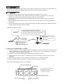
Service Space for Multiple Outdoor Units Installation
Sealing Procedures (Example)
1
Sealing Agent
(field-supplied)
(field-supplied)
Fill the screw hole
with sealing agent.
Field Supplied
Materials
Clear Sealing Agent with High Viscosity
A silicone (RTV) sealant with a temperature range
from -65
o
F to 650
o
F (-54
o
C to 343
o
C) intermittent.
Cloth for wiping off surplus sealing agent
Screw into the hole filled with
sealing agent.
* Wipe off any excess sealer
with a cloth.
Screw
(accessories)
Sealing Agent
2
Hood for Left Side Air Inlet
Outdoor Units
Min. 2 inch (50mm) Min. 2 inch (50mm)
Hood for Right Side Air Inlet
If no air inlet hood is provided
between outdoor units,
2 inch (50mm) or more space
is required for servicing.
To hold the snow protection hood properly to the outdoor unit against a strong wind or an earthquake, use
safety wire rope reinforced installation and to prevent the outdoor unit from overturning.
● Install the snow protection hood to avoid direct facing the seasonal or strong wind.
● Protect the screws and the snow protection hood from scratches or scrapes that may cause rust.
Handle with care the snow protection hood during assembly and installation.
● Apply touch-up coating or sealing (eld-supplied) at the screw holes of the outdoor unit in order to
prevent rusting.
● Even though the hood is stainless, salt or iron may cause rust. Be aware of this during installation or
maintenance.
● The snow protection hood is heavy-weight. More than two people are required for installation. Be sure
to wear personal protective equipment (PPE).
3. Selection of Installation Location
(1) Install the outdoor unit at the suitable height in consideration of snow accumulation. Increase the base
height or additionally provide the frame under the unit (higher than snow accumulation), and secure
the outdoor unit securely with anchor bolts.
(2) Install the unit at location where fallen snow from the building does not hit.
(3) Ensure adequate service space in consideration of snow accumulation height and snow removal
operation.
(4) Clear away any obstacles. There must be no obstacles in the air discharge direction.
(5) When installing multiple outdoor units, provide service space as shown below.
2

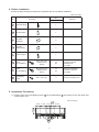
Unit: inch (mm)
No. Accessory
Qty.
Remarks
ASG-TP50BCS
1
Right Side Plate 1
2
Left Side Plate 1
3
Faceplate
(Top Side)
2
4
Faceplate
(Bottom Side)
2
5
Center Support 1
6
Screw
(for Installation)
M5 x 1/2L (12L)
(tapping screw
type B)
22
(2)
Used for installation.
Use with a burred,
threaded hole.
(2): Spare
7
Screw
(for Assembling)
M5 x 9/16L (14L)
(tapping screw
type C)
30
(2)
Used for assembling.
Use with a weld nut.
(2): Spare
8
Self-Tapping
Screw
M4 x 1/2L (13L) 3 Used for preparing hole.
4. Before Installation
Check that all the following accessories are packed with the unit before installation.
5. Installation Procedures
(1) Prepare holes using self-tapping screw (
8
) at the indentations
P
(six places) on the rear upper side
of the outdoor unit.
P
13-3/16
(335)
1-5/16
(33)
10-5/8
(270)
12-3/16
(309)
8-1/4
(209)
8-1/4
(209)
12-3/16
(309)
Unit: inch (mm)
3

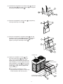
(2) Assemble the faceplate for the bottom side (
4
) with the
right side plate (
1
) and center support (
5
), and tighten
by using six assembly screws (
7
).
(3) Secure the faceplate for the top side (
3
) by tightening
with eight assembly screws (
7
).
(5) Tighten the installation screws (
6
) into
the holes made at part
P
(six places) in
step (1) but not the all way down. After
hooking the snow protection hood (for rear
side installation), securely tighten the other
eight installation screws (
6
) and the other
six places for center stay using installation
screws (
6
). Finally, securely tighten the
upper six screws.
Use a stubby screwdriver or other
appropriate tool to tighten the center stay
screws located in the narrow space.
7
3
7
3
2
4
7
Snow Protection Hood
(for Rear Side Installation)
Outdoor Unit
6
6
6
(Upper
Part Screws)
6
1
4
7
5
(4) Secure the faceplate for the bottom side (
4
) then the
faceplate for the top side (
3
) between the assembled
parts from step (3) and the left side plate (
2
), and
tighten by using the assembly screws (
7
).
4

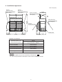
6. Installation Appearance
Hood for
Side Air Inlet
(Other Snow Protection
Hood Option)
Hood for
Left Side Air Inlet
(Other Snow Protection
Hood Option)
89-1/8
(2264)
Hood for Air Outlet
(Other Snow Protection
Hood Option)
Outdoor Unit
Safety Wire Rope
to Prevent Overturning
(Field-Supplied)
Hood for
Rear Side Air Inlet
15-3/4
(400)
15-3/4
(400)
63
(1600)
15-3/4
(400)
30-1/8
(765)
30-1/8
(765)
NOTICE:
This manual applies only to the combination indicated with .
For other snow protection hood options, refer to each installation manual.
Available Combinations
Applicable Outdoor Unit
(Representative Model)
Model
(H,Y)VAHP168, 192B32S
(H,Y)VAHP168, 192B42S
Hood for Air Outlet ASG-TP50FCS
Hood for Rear Side Air Inlet ASG-TP50BCS
Hood for Left Side Air Inlet ASG-TP50RS
Hood for Right Side Air Inlet ASG-TP50RS
Unit: inch (mm)
5

7. Maintenance and Servicing
Even if during the warranty period, the snow protection hood becomes rusted under conditions that are
caused by alkaline or corrosive moisture, it is recommended to provide salt damage resistance products to
prevent such damage.
In order to prolong the product life, perform periodical maintenance to prevent signicant aging due to
deterioration. Perform the following tasks as part of routine preventative maintenance for the equipment.
(1) Red Rust Generation Check
If red rust is generated, scour the rust off.
(2) Retighten installation and assembly screws.
Check for loose screws and retighten when inspection and maintenance is performed. In order to
prevent screw breakage, be sure to tighten to the following torque specications:
* M5 Tapping Screw Type C for Assembling
7
: 2.6 + 0.7 [Ibf-ft] (3.5 + 1.0 [N•m])
* M5 Tapping Screw Type B for Installation
6
: 1.8 + 0.7 [Ibf-ft] (2.5 + 1.0 [N•m])
© 2017 Johnson Controls, Inc.
Code No. LIT-12012440
Issued February 2017
P5416964
-
 1
1
-
 2
2
-
 3
3
-
 4
4
-
 5
5
-
 6
6


York VRF Heat Pump Outdoor Units 208/230V Installation guide
- Type
- Installation guide
- This manual is also suitable for
Ask a question and I''ll find the answer in the document
Finding information in a document is now easier with AI
Related papers
-
York VRF Heat Recovery Outdoor Units 460V Installation guide
-
-
-
York VRF Heat Pump Outdoor Units 460V Installation guide
-
-
-
-
-
-
Other documents
-
Hitachi RAS-(4-12)HNC(1)(E) User manual
-
Hitachi RAS-(4-10)HRNS(2)E User manual
-
Hitachi RAS-12-HNPE User manual
-
-
Hitachi RAS-8HNPE Operating instructions
-
Johnson Controls HVAHR360B42S Installation and Maintenance Manual
-
Johnson Controls DHMW24NKB21S Owner's manual
-
Lexus LFA Owner's manual
-
Eureka! Tents Headquarters User manual
-
BOMBARDIER Citation LSE User manual