Page is loading ...

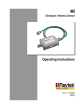
MI
Miniature Infrared Sensor
Operating Instructions
Rev. E 10/2004
54301
Noncontact Temperature Measuremen
t

Declaratio nofConformityfortheEuropeanCommunit
y
Thisinstrumentconformsto:
EMC: IEC/EN61326‐1
Safety: EN61010‐1:1993/A2:1995

Contacts
Europe
RaytekGmbH
Berlin,Germany
Tel: +4930478008–0
+4930478008–400(Ventes)
Fax: +49304710251
USA
RaytekCorporation
SantaCruz,CAUSA
Tel: +1831458–1110ou
+1800227–8074
Fax: +1831458–1239
automation@raytek.com
UnitedKingdom
Tel: +441908630800
Fax: +441908630900
RaytekJapan,Inc.
Tokyo
Tel: +81(‐3)57336065
Fax: +81(‐3)57336099
RaytekFrance
Palaiseau,France
Tel: +33164531540
Fax: +33164531544
RaytekChine
Beijing,China
Tel: +861064392255
Fax: +861064370285
RaytekdoBrasil
Sorocaba,SPBrazil
Tel: +551532176046
Fax: +55532175694
Internet:http://www.raytek.com/
©RaytekCorporation.
Raytek,theRaytekLogo,andDataTempareregisteredtrademarksofRaytekCorporation.
Allrightsreserved.Specificationssubjecttochangewithoutnotice.

WARRANTY
Themanufacturerwarrantsthisinstrumenttobefreefromdefectsin
material and workmanship under normal use and service for the
period of two years from date of purchase. This warranty extends
onlytotheoriginalpurchaser.Thiswarrantyshallnotapplytofuses,
batteries, or any product that has been
subject to misuse, neglect,
accident,orabnormalconditionsofoperation.
In the event of failure of a product covered by this warranty, the
manufacturer will repair the instrument when it is returned by the
purchaser, freight prepaid, to an authorized Service Facility within
the applicable warranty period, provided manufacturer’s
examination
discloses to its satisfaction that the product was
defective.Themanufacturermay,atitsoption,replacetheproductin
lieu of repair. With regardto any covered product returned within
theapplicablewarrantyperiod,repairsorreplacementwillbemade
without charge and with return freight paid by the manufacturer,
unless
the failure was caused by misuse, neglect, accident, or
abnormal conditions of operation or storage, in which case repairs
willbebilledatareasonablecost.Insuchacase,anestimatewillbe
submittedbeforeworkisstarted,ifrequested.
THE FOREGOING WARRANTY IS IN LIEU OF ALL OTHER
WARRANTIES, EXPRESSED OR IMPLIED, INCLUDING BUT
NOT LIMITED TO ANY IMPLIED WARRANTY OF
MERCHANTABILITY, FITNESS, OR ADEQUACY FOR ANY
PARTICULAR PURPOSE OR USE. THE MANUFACTURER
SHALL NOT BE LIABLE FOR ANY SPECIAL, INCIDENTAL OR
CONSEQUENTIAL DAMAGES, WHETHER IN CONTRACT,
TORT,OROTHERWISE.

TABLEOFCONTENTS
1SAFETYINSTRUCTIONS............................................1
2DESCRIPTION ...............................................................3
3TECHNICALDATA ......................................................4
3.1MEASUREMENTSPECIFICATIONS...............................4
3.2OPTICALSPECIFICATIONS ..........................................6
3.3ELECTRICALSPECIFICATIONS ....................................7
3.4ENVIRONMENTALSPECIFICATIONS ...........................8
3.5DIMENSIONS...............................................................9
3.6SCOPEOFDELIVERY .................................................10
4BASICS...........................................................................11
4.1MEASUREMENTOFINFRAREDTEMPERATURE.........11
4.2EMISSIVITYOFTARGETOBJECT................................12
4.3AMBIENTTEMPERATURE .........................................12
4.4ATMOSPHERICQUALITY ..........................................12
4.5ELECTRICALINTERFERENCE ....................................13
5INSTALLATION ..........................................................14
5.1POSITIONING ............................................................14
5.1.1DistancetoObject ............................................. 14
5.2WIRING.....................................................................15
5.2.1SensorHeadCable ............................................ 15
5.2.2CablePreparations ............................................ 16
5.3OUTPUTS...................................................................18

5.3.1SignalOutput ................................................... 19
5.3.2HeadAmbientTemp./AlarmOutput ............. 20
5.3.3ThermocoupleOutput....................................... 22
5.4INPUTSFTC.............................................................. 23
5.4.1EmissivitySetting(analogcontrolled) ............. 24
5.4.2EmissivitySetting(digitalcontrolled) ............. 25
5.4.3AmbientBackgroundTemperature
Compensation ............................................................ 26
5.4.4TriggerandHoldFunction............................... 28
5.5CONNECTINGTOTHEPCVIARS232 ...................... 30
5.6INSTALLINGOFMULTIPLESENSORSVIARS485...... 31
6OPERATION................................................................. 34
6.1CONTROLPANEL ..................................................... 34
6.2SETTINGOFMODES.................................................. 35
6.3SETTINGTHEOUTPUTJUMPER ................................ 37
6.4POSTPROCESSING.................................................... 38
6.4.1Averaging ......................................................... 38
6.4.2PeakHold .......................................................... 40
6.4.3ValleyHold ....................................................... 41
6.4.4AdvancedPeakHold ......................................... 42
6.4.5AdvancedValleyHold ...................................... 43
6.4.6AdvancedPeakHoldwithAveraging............... 43
6.4.7AdvancedValleyHoldwithAveraging ............ 43
6.5FACTORYDEFAULTS ................................................ 44
7OPTIONS....................................................................... 45

8ACCESSORIES .............................................................46
8.1OVERVIEW ................................................................46
8.2ADJUSTABLEMOUNTINGBRACKET.........................48
8.3FIXEDMOUNTINGBRACKET ....................................49
8.4AIRPURGINGJACKET...............................................50
8.5AIRCOOLINGSYSTEM..............................................52
8.6RIGHTANGLEMIRROR ............................................57
8.7BOXLID ....................................................................58
8.8PROTECTIVEWINDOW .............................................59
9MAINTENANCE..........................................................60
9.1TROUBLESHOOTINGMINORPROBLEMS ..................60
9.2FAIL‐SAFEOPERATION ............................................61
9.3SENSINGHEADEXCHANGE .....................................63
10SOFTWARE.................................................................64
11PROGRAMMINGGUIDE .......................................65
11.1TRANSFERMODES..................................................66
11.2GENERALCOMMANDSTRUCTURE ........................67
11.3DEVICEINFORMATION...........................................68
11.4DEVICESETUP ........................................................69
11.4.1TemperatureCalculation ................................ 69
11.4.2EmissivitySettingandAlarmSetpoints ....... 69
11.4.3PostProcessing ............................................... 71
11.5DYNAMICDATA.....................................................71
11.6DEVICECONTROL ..................................................72
11.6.1OutputfortheTargetTemperature ................ 72

11.6.2AnalogOutput,Scaling ................................. 72
11.6.3AlarmOutput ................................................. 72
11.6.4Factorydefaultvalues ..................................... 72
11.6.5LockMode ....................................................... 73
11.6.6ModeSettingfortheDigitalInputFTC3....... 73
11.6.7ChangingtheSensingHeadCalibrationData 73
11.6.8AmbientBackgroundTemperature
Compensation ............................................................ 73
11.7MULTIPLEUNITS.................................................... 75
11.8COMMANDSET ...................................................... 76
12APPENDIX...................................................................80
12.1DETERMINATIONOFEMISSIVITY ........................... 80
12.2TYPICALEMISSIVITYVALUES ................................ 81
INDEX ............................................................................... 85

SafetyInstructions
1SafetyInstructions
This document contains important information, which should be
keptatalltimeswiththeinstrumentduringitsoperationallife.Other
usersofthisinstrumentshouldbegiven theseinstructionswith the
instrument. Eventual updates to this informationmust be added to
the original document. The instrument should only be operated by
trained personnel in accordance with these instructions and local
safetyregulations.
AcceptableOperation
This instrument is intended only for the measurement of
temperature.The instrumentisappropriateforcontinuoususe. The
instrument operates reliably in demanding conditions, such as in
high environmental temperatures, as long as the documented
technicalspecifications
forallinstrumentcomponentsareadheredto.
Compliancewiththeoperatinginstructionsisnecessarytoensurethe
expectedresults.
UnacceptableOperation
Theinstrumentshouldnotbeusedformedicaldiagnosis.
ReplacementPartsandAccessories
Use only original parts and accessories approved by the
manufacturer. The use of other products can compromise
the
operationalsafetyandfunctionalityoftheinstrument.
InstrumentDisposal
Disposal of old instruments should be handled according to
professionalandenvironmentalregulationsaselectronicwaste.
MID 1

SafetyInstructions
OperatingInstructions
The following symbols are used to highlight essential safety
informationintheoperationinstructions:
Helpful information regarding the optimal use of the
instrument.
Warnings concerning operation to avoid instrument
damage.
Warningsconcerningoperationtoavoidpersonalinjury.
Payparticularattentiontothefollowingsafetyinstructions.
Use in 110 /
230 VAC electrical systems can result in
electrical hazards and personal injury if not properly
protected.Allinstrumentpartssuppliedbyelectricitymust
becoveredtopreventphysicalcontact andotherhazardsat
alltimes.
2 MID

Description
2Description
The miniature infrared sensors MI are noncontact infrared
temperature measurementsystems.Theyaccuratelyandrepeatably
measure the amount of energy emitted from an object and convert
thatenergyintoatemperaturesignal.
Thefollowingoutputsareavailable:
• J‐Thermocouple
• K‐Thermocouple
• 0‐5Volt
• 0‐20mAor
4‐20mA
• 10mV/°Cheadambienttemperaturesignal
• RS232interface
• optional:RS485interface
ThesensingheadisprotectedbyaruggedIEC529(IP65,NEMA‐4)
stainlesssteelhousing,andisconnectedtotheelectronicboxwitha
1m (3ft) cable. Longer cables
must be ordere d as an option. The
electronic box is separa ted from the sensing head. This allows the
sensing head to be used in hot environments up to 180°C (356°F)
without cooling. The electronic box can only be used in ambient
temperaturesupto65°C(150°F).
MID 3

TechnicalData
3TechnicalData
3.1MeasurementSpecifications
TemperatureRange
LT‐40to600°C(‐40to1112°F)
forJ‐Thermocouple:‐25to600°C(‐13to1112°F)
SpectralResponse
LT 8to14μm
ResponseTime
Allmodels 150ms(95%response)
Accuracy
LT ±1%or±1°C(±2°F)whicheverisgreater
LT ±2°C(±
4°F)fortargettemp.<–20°C(4°F)
TCoutputs ±1%or±2.5°C(±5°F)whicheverisgreater
Atambienttemperature23°C±5°C(73°F±9°F)
Repeatability
Allmodels ±0.5%or±0.5°C(±1°F)whicheverisgreater
4 MID

TechnicalData
TemperatureResolution
LT ±0.1K(±0.2°F)*
±0.25K(±0.5°F)**
Atambienttemperature23°C±5°C(73°F±9°F)
*Forazoomedtemperaturespanof300°C(600°F)
**Forthefulltemperaturerangeoftheunit
TemperatureCoefficient
MIC ±0.05KperKor±0,05%/Kwhicheveris
greater,atambient:23to125°C(73to185°F)
MIH ±0.05KperKor±0,05%
/Kwhicheveris
greater,atambient:23to180°C(73to356°F)
MIC,MIH ±0.1KperKor±0.1%perKwhicheveris
greater,atambient:0to23°C(32to73°F)
MID ±0.15KperKor±0.15%perKwhicheveris
greater,
atambient:0to85°C(32to185°F)
Box ±0.1KperKor±0.1%perKwhicheveris
greater
ThermalShock(within20min.)
LT ±3.5Kat∆T
ambient=25K(45°F)
attargettemperatureof50°C(45°F)
Emissivity
Allmodels 0.100to1.100
Transmission
Allmodels 0.100to1.000
MID 5

TechnicalData
3.2OpticalSpecifications
OpticalResolutionD:S
MID,MIC 2:1or10:1
MIH 10:1
At90%energyinminimumanddistance400mm(15.7in.)
Distance: Sensor to Object [in]
Spot Diameter [in] Spot Diameter [mm]
Distance: Sensor to Object [mm]
Figure1:SpotSizeChart
6 MID

TechnicalData
3.3ElectricalSpecifications
PowerSupply
Voltage 12to24VDC
Current 100mA
Outputs
1.Output(OUT) 0to20mA,or
4to20mA,or
0to5V,or
Thermocouple(JorK)
2.Output(AMB)0to5Voutputforheadambienttemperature
(0to500°C,32to932°F)
oroutputforalarm
relay(softwareenabled,onlyinconjunction
withRS232/485)
mAOutput recommendedlo opimpedanceseeFigure9on
page19.
0to5VOutputs min.loadimpedance100kΩ(alowerload
impedancedeterioratestheaccuracy)
outputimpedance100Ω
shortcircuitresistant
Thermocouple outputimpedance20Ω
shortcircuitresistant
MID 7

TechnicalData
3.4EnvironmentalSpecifications
AmbientTemperature
MIHsensinghead 0to180°C(32to356°F)
MICsensinghead 0to125°C(32to257°F)
MIDsensinghead 0to85°C(32to185°F)
MIDwithaircooling‐18to200°C(0to392°F)
Electronicsbox 0to65°C(32to150°F)
StorageTemperature ‐18
to85°C(0to185°F)
Rating(Head) IP65(NEMA‐4),onlyformodelswith
anopticalresolutionof10:1
Rating(Box) IP65(NEMA‐4)
RelativeHumidity 10%to95%non‐condensing
EMI IEC801‐3,level3
max.cablelength3m(118in.)
Vibration(Head) IEC68‐2
‐6:3G´s,11to200Hz,anyaxis
Shock(Head) IEC68‐2‐27:50G´s,11ms,anyaxis
Weight(Head) 50g(2oz.)with1mcable,stainlesssteel
Weight(Box) 270g(10oz.),die‐castzinc
HeadCableMaterial
MID/MIC PUR(Polyurethane),Halogenfree,
Siliconefree
MIH Teflon
Teflon develops poisonous ga sses when it comes into
contactwithflames!
8 MID

TechnicalData
3.5Dimensions
Standard cable length
1 m (3 ft.)
MID/MIC: Ø 5 mm (0.2 in)
MIH: Ø 3 mm (0.12 in)
Figure2:DimensionsofSensingHead
2 mounting holes,
Ø 4.5 mm
(
0.17 in
)
Figure3:DimensionsofElectronicBox
MID 9

TechnicalData
3.6ScopeofDelivery
Thescopeofdeliveryincludesthefollowing:
• Sensinghead
• 1mheadcable
• Mountingnut
• Electronicbox
• Operatinginstructions
10 MID

Basics
4Basics
4.1MeasurementofInfraredTemperature
All surfaces emit infrared radiation The intensity of this infrared
radiation changes according to the temperature of the object.
Depending on the material and surface properties, the emitted
radiationliesinawavelengthspectrumofapproximately1to20μm.
Theintensityoftheinfraredradiation(”heatradiation”)isdependent
on
the material. For many substances this material‐dependent
constant is known. This constant is referred to as the ”emissivity
value”.
Infrared

Basics
4.2EmissivityofTargetObject
Todeterminetheemissivityof thetarget objectrefertosection12.1
Determination of Emissivity on page 80. If emissivity is low,
measured results could be falsified by interferinginfraredradiation
from background objects (such as heating systems, flames, firec lay
bricks, etc. close beside or behind the target object). This type of
problemcanoccurwhenmeasuringreflectivesurfacesandverythin
materialssuchas
plasticfilmsandglass.
Thismeasurement error can be reduced to a minimum if particular
care is taken during installation, and the sensing head is shielded
fromthesereflectingradiationsources.
4.3AmbientTemperature
The sensing head was developed for the following ambient
temperatureranges:
• MIH:0to180°C(32to356°F)
• MIC: 0to125°C(32to257°F)
• MID:0to85°C(32to185°F)
The MID can operate in ambient temperatures up to 200°C (392°F)
withtheair‐coolingaccessory.
4.4AtmosphericQuality
If the lens gets dirty, infrared energy will be blocked and the
instrumentwillnotmeasureaccurately.Itisgoodpracticetoalways
keep the lens clean. The Air Purge Jacket helps keep contaminants
from building up on the lens. If you use air purging, make sure a
filtered air supply
with clean dry air at the correct air pressure is
installedbeforeproceedingwiththesensorinstallation.
12 MID
/


