Eizo FDF2304W-IP Owner's manual

Type
Owner's manual

Eizo FDF2304W-IP is a versatile Color LCD Monitor designed to seamlessly integrate with network cameras, offering a range of monitoring and control capabilities. With the ability to display images from up to 16 network cameras simultaneously, it's an ideal solution for surveillance and security systems.

Eizo FDF2304W-IP is a versatile Color LCD Monitor designed to seamlessly integrate with network cameras, offering a range of monitoring and control capabilities. With the ability to display images from up to 16 network cameras simultaneously, it's an ideal solution for surveillance and security systems.

Color LCD Monitor
Instruction Manual
Important
Please read this “Instruction Manual”, the “Installation Manual” and
the “Setup Manual” carefully to familiarize yourself with safe and
effective usage.
For the latest product information including the “Instruction Manual”,
refer to our web site:
http://www.eizoglobal.com
Software Version 4.3
Thank you for purchasing our Color LCD Monitor.
2
About this manual
Setup Manual
Describes precautions and setup processes from network camera
connection to camera image display.
Instruction Manual
(this manual)
Describes operation of network cameras and live image screen
menus, etc.
Installation Manual
Describes network camera registration and function setup, monitor
system setup, etc.
This product has been adjusted specically for use in the region to which it was originally shipped. If
operated outside this region, the product may not perform as stated in the specications.
No part of this manual may be reproduced, stored in a retrieval system, or transmitted, in any form or by
any means, electronic, mechanical, or otherwise, without the prior written permission of EIZO Corporation.
EIZO Corporation is under no obligation to hold any submitted material or information condential unless
prior arrangements are made pursuant to EIZO Corporation’s receipt of said information. Although every
effort has been made to ensure that this manual provides up-to-date information, please note that EIZO
monitor specications are subject to change without notice.
3
Notice for this monitor
Cleaning
The stains on the cabinet and LCD panel surface can be removed by moistening part of a soft cloth with water.
Attention
Chemicals such as alcohol and antiseptic solution may cause gloss variation, tarnishing, and fading of the cabinet
or LCD panel, and also quality deterioration of the image.
Never use thinner, benzine, wax, or abrasive cleaner as they may damage the cabinet or LCD panel surface.
Note
It is recommended that ScreenCleaner (available as an option) be used to clean the cabinet and LCD panel surface.
To use the monitor comfortably
An excessively dark or bright screen may affect your eyes. Adjust the brightness of the monitor
according to the environmental conditions.
Staring at the monitor for a long time tires your eyes. Take a 10-minute rest every hour.
4
CONTENTS
CONTENTS
Notice for this monitor ......................................... 3
Cleaning .................................................................... 3
To use the monitor comfortably ............................. 3
CONTENTS ............................................................. 4
Chapter 1 Product overview .............................. 5
1-1. SystemConguration .................................. 5
Chapter 2 Turning On / Off the Power .............. 6
To turn on the power ....................................... 6
To turn off the power ....................................... 6
Chapter 3 Operating the System ...................... 7
3-1. Remote Control ............................................. 7
3-2. Live Image Screen ........................................ 8
Basic menu operations.................................... 9
3-3. Changing Over Screen Layout and
Displayed Pages...........................................12
To change over the screen layout ..................12
To change over the page displayed on
the screen.......................................................13
To switch camera image display positions .....14
3-4. Turning Visibility Optimizer Function
On / Off ..........................................................15
3-5. Controlling Network Cameras ....................15
Before operation .............................................15
To Operate network cameras .........................17
3-6. Adjusting Screen Brightness .....................19
3-7. To switch among input signals ..................19
Chapter 4 Troubleshooting .............................. 20
4-1. No picture .................................................... 20
4-2. Imaging problems ....................................... 20
4-3. Other problems ............................................21
5
Chapter 1 Product overview
This color LCD monitor can display images from up to 16 network cameras
*1
.
*1 A type of camera which converts images into network signals and transmits the signals.
1-1. SystemConguration
FDF2304W-IP
HDMI
Ethernet
Network camera
*1
Network hub
HDMI device
*2
(Network video recorder etc.)
*1 Up to 16 network cameras can be registered.
*2 Use an HDMI device (e.g. network video recorder) if necessary.
6
Chapter 2 Turning On / Off the Power
To turn on the power
1.
Turn on the main power switch on the back of the monitor.
The main power switch is turned on when factory default settings are congured.
2.
Press on the front of the monitor or on the remote control.
The power indicator lights up blue and the live image screen is displayed.
(For details on the live image screen, refer to “3-2. Live Image Screen” (page 8).)
Attention
By default, it takes approximately one minute for the live image screen to be displayed after the power is turned
on (A rotating bar indicating startup is displayed). Do not turn off the monitor during startup.
When the monitor is started up for the rst time, a menu for operating the monitor and network cameras is
displayed.
When no network camera is registered, a “Not Registered” message is displayed at the network camera image
display area.
Note
The time required to display the live image screen can be reduced (Quick Start) by changing the power-off status.
For details, refer to the Installation Manual.
To turn off the power
1.
Press on the front of the monitor or on the remote control.
Attention
The power indicator ashes blue while the system is shutting down.
The power-off status differs depending on the “Quick Start” setting. For details, refer to the Installation Manual.
- When set to “On”: Part of the system remains running. (Power Indicator: Red)
- When set to “Off”: The system is shut down completely (default setting). (Power Indicator: OFF)
When turning off the main power of the monitor, follow the procedure below.
1. If “Quick Start” is set to “On”, change the setting to “Off.
2. Press
on the front of the monitor or on the remote control to turn off the power.
The system is shut down and the power indicator turns off.
3. Turn off the main power switch.
Turning off the main power of the monitor before the system completely shuts down may cause equipment
damage.
Use the remote control within the range illustrated in the diagram below.
5m
5m
20°
20°
7m
5m
30°
30°
7m
5m
When installing multip le monitors, leave sufcient space between each monitor so that only the intended monitor
will be operated by the remote control. Otherwise, all monitors that receive the remote control signal will operate
accordingly.
7
Chapter 3 Operating the System
Each menu is operated using the remote control or a USB mouse.
This chapter describes operating the menus using the remote control. To operate menus when using a USB
mouse, refer to each item. For details on connecting a USB mouse, refer to “Basic menu operations” (page
9).
3-1. Remote Control
2
3
9
1
4
5
6
8
7
13
11
12
10
Name Description
1.
Switches input signals for display.
2.
Turns the power on or off.
3.
Used to display / exit the monitor’s Adjustment menu.
4.
/
Adjusts the brightness of the monitor screen.
5. Number Buttons
( 0 to 9 ) /
Used to enter numbers and letters.
6.
/
Adjusts the network camera display magnication.
7.
/ / / ,
Used to set and control (pan / tilt) network cameras, and congure system
settings of the monitor.
8.
Returns to the previous menu status in menu operation.
9.
Changes the live image screen layout.
Each time the button is pressed, the layout changes in the following order:
1 Screen → 3 Screens → 4 Screens → 9 Screens → 16 Screens → 8 Screens →
Custom Screen → 1 Screen.
10.
Displays / hides the menu of the live image screen.
11.
*1
Turns Visibility Optimizer function on or off.
12.
Turns the sequential display of camera images on or off.
13.
/
Changes the camera image page to display on the live image screen.
*1 Some remote controls are labeled “Smart.
8
Chapter 3 Operating the System
3-2. Live Image Screen
The live image screen is displayed when the monitor is turned on.
There are two states to the live image screen. Live image screen menu can be shown or hidden by
pressing .
Live image screen
(camera images and menu)
Live image screen
(camera images only)
Note
You can also operate the live image screen from your Web browser. For information on operation from a Web
browser, refer to the Installation Manual.
9
Chapter 3 Operating the System
Basic menu operations
The menu is used for operation and setting of network cameras and the monitor.
Live Image Screen
Network camera image display area
When no camera is registered, a “Not registered ” message is displayed.
When an input signal is not supported, the “Unsupport resolution” message is displayed.
Message display area
(Error messages such as on camera operations are displayed.)
Current time
Display mode menu
System setup menu / Camera control menu
Attention
When sequence display is enabled, the system setup menu and the camera control menu are inoperable.
Note
The displayed menus can be operated by remote control even if the menus on the live image screen are
hidden.
When using a USB mouse to operate the menu
- Connect the mouse to the USB downstream port at the back of the monitor.
10
Chapter 3 Operating the System
Display mode menu
Camera images displayed on the live screen can be operated.
Display mode menu
Remote control
button
Description
Displays / hides the menu of the live image display screen.
Changes the live image screen layout.
Each time the button is pressed, the layout changes in the
following order:
1 Screen → 3 Screens → 4 Screens → 9 Screens →
16 Screens → 8 Screens → Custom Screen → 1 Screen.
*1
Turns Visibility Optimizer function on or off.
Turns the sequence display of the camera image (mode
that switches the display page at regular intervals) on or
off.
/
Changes the camera image page to display on the live
image screen.
*1 Some remote controls are labeled “Smart.
System setup menu / Camera control menu
The system settings menu is used for logging into and conguring the system.
The camera control menu controls network cameras from the monitor in the camera operation menu.
Item Operation method
To select an item Press the / / / buttons.
To conrm a selected item Press
.
To change a setting With setting buttons:
Press
. (Excluding zoom in / out and position adjustment)
With list box:
1. Press .
The list box is highlighted in green.
2. Select the setting with
or .
3. Press
.
To return to the previous menu level
Press
.
Note
When canceling a setting change in process, press .
11
Chapter 3 Operating the System
Entering characters
1. Press
.
The text eld is highlighted in green.
2. Press the number buttons ( 0 to 9 ).
Press a button consecutively to change over to the character next in order. For the order of character entry,
refer to the table shown below.
Button Input characters
0 0 - _ : . / (space)
1 1
2 a b c A B C 2
3 d e f D E F 3
4 g h i G H I 4
5 j k l J K L 5
6 m n o M N O 6
7 p q r s P Q R S 7
8 t u v T U V 8
9 w x y z W X Y Z 9
To enter a new character, press
.
To delete a character, press
.
3. Press
.
Note
Entering network addresses
Network address text elds are separated by [.] (a period mark).
- When a three-digit number is entered, the cursor automatically moves to the next entry position.
- When entering a two-digit or one-digit number, press
to move to the next entry position.
When using a USB mouse
- When you enter a period “., the cursor moves to the next entry position.
- To enter characters, click “Keyboard” on the character entry screen. Then click the keys on the displayed
keyboard to enter characters.
Attention
The remote control cannot be used to select the character entry screen keyboard.
The operable range of the menu differs according to the level of the user accessing this product.
There are three user levels: “LIVE”, “CAMERA CONTROL” and “ADMIN”. The range of operation for each
level is shown below.
(: Operable, -: Inoperable)
Operation
Level
Display
mode menu
System setup menu
Camera control
menu
Switching camera
image display
positions
Login operation System settings
LIVE - - -
CAMERA
CONTROL
- -
ADMIN
When the power is turned on and after logoff, the user level is “LIVE”.
For information on setting user levels, refer to the Installation Manual.
12
Chapter 3 Operating the System
3-3. Changing Over Screen Layout and Displayed Pages
To change over the screen layout
Changes the number of camera images to display on the live image screen.
Procedure
1. Press
on the remote control.
Each time the button is pressed, the screen layout changes over. When using a USB mouse, the screen
layout changes by selecting the display screen layout icon.
1 Screen
8 Screens
3 Screens 4 Screens
9 Screens
16 ScreensCustom Screen
Attention
When displaying the image layout in three screens:
Suitable for portrait input images. To display portrait images, network cameras require separate settings. For
details on the settings, refer to the network camera User’s Manual.
Note
The selected network camera image is displayed in one screen by selecting the live image screen network
camera image and pressing
on the remote control.
13
Chapter 3 Operating the System
To change over the page displayed on the screen
Except for when the screen layout is 16 Screens, camera images are displayed by changing over
pages.
Pages can be changed over either manually or automatically at a set interval (sequential display).
Note
When “Custom Screen” is specied for the screen layout, the number of pages varies depending on the
specied number of screens.
Changing pages manually
Procedure
1. Press
or on the remote control.
Each time the button is pressed, the page displayed on the screen changes over. When using a USB mouse,
select
or in the display menu.
Example: 4 Screens layout
Camera 1 Camera 2
Camera 3 Camera 4
Camera 5 Camera 6
Camera 7 Camera 8
Camera 9
Camera 10
Camera 11 Camera 12
Camera 13 Camera 14
Camera 15
Camera 16
Changing pages automatically (Sequential display)
Procedure
1. Press
on the remote control.
Pages displayed on the screen are changed over automatically at a specied interval.
Note
The interval for page changeover can be changed (default setting: 5 sec). For information on how to change
the display interval, refer to the Installation Manual.
To stop sequential display, press
again.
Attention
During sequential display, camera control is disabled and the setting screen cannot be displayed. The
sequential display must be stopped in order to operate cameras or display the setting screen. For information
on how to display the setting screen, refer to the Installation Manual.
Only pages registered for the network camera are displayed in the sequence display. Pages not registered
with the camera will not be displayed.
14
Chapter 3 Operating the System
To switch camera image display positions
If the image layout is displayed in multiple screens other than one screen, camera image display
positions can be switched.
Drag and drop the camera image on the live image screen, and the display positions of the source
and destination camera image are switched.
Attention
It is necessary to log in as a user with a user level of “ADMIN.
It is possible to switch all the display positions of the registered network cameras.
Procedure
1. Using a USB mouse, drag the camera image and drop it on a position where you want to display
it.
The display positions of the source and destination camera image are switched.
15
Chapter 3 Operating the System
3-4. Turning Visibility Optimizer Function On / Off
Enable or disable settings of Visibility Optimizer function. Using the Visibility Optimizer function improves
the camera image visibility.
Procedure
1. Press
*1
on the remote control. (*1 Some remote controls are labeled “Smart”.)
Each time the button is pressed, Visibility Optimizer function is turned on or off.
Note
For information on how to congure the Visibility Optimizer function, refer to the Installation Manual.
3-5. Controlling Network Cameras
Before operation
Network camera control is allowed only when the level of the user accessing this product is
“CAMERA CONTROL” or “ADMIN”.
Be sure to log in to the system with a user account of either of these levels.
Procedure
1. Select
(Login) under “System”.
The login screen is displayed.
1
2
3
2. Enter a username and a password.
3. Select “Login”.
The display returns to the live image screen.
16
Chapter 3 Operating the System
4. Press on the remote control.
The system frame is selected (highlighted in green).
Note
For information on how to enter characters, refer to “Entering characters” (page 11).
The following user information is set by default:
- Username: “admin”
- Password: “admin”
- User Level: “ADMIN”
For information on how to congure users, refer to the Installation Manual.
It is recommended that you log out after completing operations, so as to prevent a third party from operating
the camera or altering the settings.
When the Auto Login settings are congured, you can log in to the system without entering the username and
password. For details, refer to the Installation Manual.
Attention
Once the Auto Login settings are congured, unauthorized operation becomes easy for a malicious third
party. Restrict the conguration to the application in an environment where sufcient security is ensured.
When the monitor power is turned off while the user is logged in, the user is logged out from the system
automatically. In such a case, you will also be logged out from the web browser.
17
Chapter 3 Operating the System
To Operate network cameras
Procedure
1. Select the camera control menu.
1. Press
.
2. Select the camera control menu using
or , then press
.
2. Select the network camera to operate.
1. Check that “Camera” is selected and press
.
2. Select a network camera displayed in the live image screen
using
or , then press . The frame around the
selected camera image become bold.
3. Press
.
3. Select a function to use.
1. Select a function to use using
or .
2. Press
.
4. Operate the functions.
Attention
Depending on the type of the network camera you are using, some functions may not be available.
There is a setting that makes the network cameras completely inoperable. For details, refer to the Installation
Manual.
Note
To select a network camera to operate, use the numerical buttons on the remote control. Also, click the USB
mouse to select an the image in the live image screen.
The position at which images in the live image screen are displayed can be changed. For details, refer to the
Installation Manual.
18
Chapter 3 Operating the System
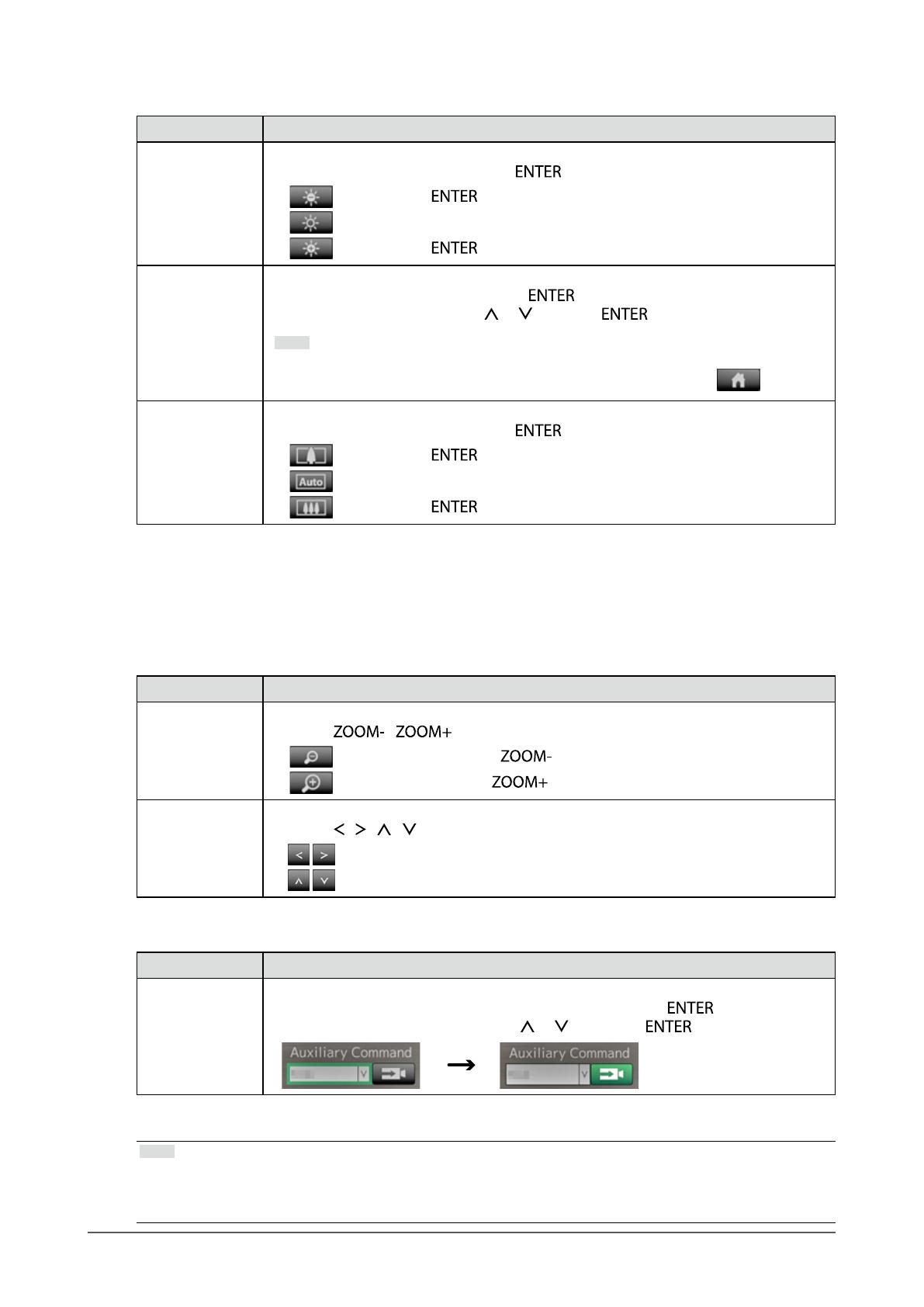
Brightness / Preset / Focus
Function Detail
Brightness Adjusts the brightness of the network camera.
1. Select the setting button and press
.
:
Each time is pressed, the image becomes darker.
:
Returns the brightness to the default setting.*
1
:
Each time is pressed, the image becomes brighter.
Preset Moves the camera orientation to the position registered in advance.
1. Select the “Preset” list box and press
.
2. Select the preset number with
or and press .
Note
For information on registering a preset position, refer to the Installation Manual.
To move the network camera orientation to the home position, select .
Focus Adjusts the network camera focus.
1. Select the setting button and press
.
:
Each time is pressed, the focus point moves closer.*
2
:
Focuses automatically.*
3
:
Each time is pressed, the focus point moves farther away.*
2
*1 Cannot be set if using a network camera for which “Protocol” is “ONVIF” or “AXIS.”
*2 If using a network camera for which “Protocol” is “ONVIF” or “AXIS,” the mode is switched to manual
adjustment mode.
*3 If using a network camera for which “Protocol” is “ONVIF” or “AXIS,” the mode is switched to automatic
adjustment mode.
Zoom / Position
Function Detail
Zoom Adjusts the network camera display magnication.
1. Press
/ .
:
Zooms out each time is pressed.
:
Zooms in each time is pressed.
Position Adjusts the shooting position of the network camera.
1. Press
/ / / .
:
Adjusts the horizontal position (pan).
:
Adjusts the vertical position (tilt).
Auxiliary Command
Function Detail
Auxiliary
Command
Operates auxiliary functions for the network camera(s).
1. Select the list box for the “Auxiliary Commands”, then press
.
*1
2. Select the auxiliary command using or , then press .
*1 Auxiliary commands can be operated using only specied devices for which the protocol is “ONVIF” or
“Panasonic”.
Note
When operating with a USB mouse, the network camera position can be adjusted automatically by clicking on
a position in the image where you wish to set as the center of the image display (only supports Panasonic or
AXIS network cameras equipped with pan, tilt, and zoom functions).
19
Chapter 3 Operating the System
3-6. Adjusting Screen Brightness
Adjust the brightness of the monitor screen by changing the brightness of the backlight (light source at
the back of the LCD panel).
Adjustable range
0 to 100
Procedure
1. Press
or on the remote control.
The brightness adjustment menu is displayed.
2. Set the brightness with or .
The menu disappears automatically after approximately ve seconds.
3 -7. To switch among input signals
Press on the remote control to change over the input signal.
When the signal is switched, the active input port name appears at the top right corner of the screen.
Note
on the monitor also can change the input.
20
Chapter 4 Troubleshooting
4-1. No picture
Problem Possible cause and remedy
1. No picture
Power indicator does not light.
Check whether the power cord is connected properly.
Turn the main power switch on.
Press
on the front of the monitor or on the
remote control.
Turn off the main power, and then turn it on again a few
minutes later.
Power indicator is lighting blue. Adjust the screen brightness (For details, refer to the
Setup Manual).
Power indicator is lighting blue. (for HDMI
input)
Check whether the HDMI cable is connected properly.
Check whether the connected device is turned on.
Pull out the HDMI cable and connect it again (For details,
refer to the Setup Manual).
4-2. Imaging problems
Problem Possible cause and remedy
1. The screen is too bright or too dark Adjust the screen brightness (For details, refer to the
Setup Manual). (The LCD monitor backlight has a limited
life span. When the screen becomes dark or begins to
icker, contact your local EIZO representative.)
2. Afterimages appear Afterimages are particular to LCD monitors. Avoid
displaying the same image for a long time.
3. Green / red / blue / white dots or defective
dots remain on the screen
This is due to LCD panel characteristics and is not a
failure.
4. Interference patterns or Pressure marks
remain on the LCD panel
Switch to the HDMI port and try displaying a white or black
image on full screen. The symptom may disappear.
  • Page 1 1
  • Page 2 2
  • Page 3 3
  • Page 4 4
  • Page 5 5
  • Page 6 6
  • Page 7 7
  • Page 8 8
  • Page 9 9
  • Page 10 10
  • Page 11 11
  • Page 12 12
  • Page 13 13
  • Page 14 14
  • Page 15 15
  • Page 16 16
  • Page 17 17
  • Page 18 18
  • Page 19 19
  • Page 20 20
  • Page 21 21
  • Page 22 22

Eizo FDF2304W-IP Owner's manual

Type
Owner's manual

Eizo FDF2304W-IP is a versatile Color LCD Monitor designed to seamlessly integrate with network cameras, offering a range of monitoring and control capabilities. With the ability to display images from up to 16 network cameras simultaneously, it's an ideal solution for surveillance and security systems.

Ask a question and I''ll find the answer in the document

Finding information in a document is now easier with AI