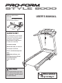
Pro-Form 995 ZLT PETL71707.2 User manual
- Category
- Treadmills
- Type
- User manual
This manual is also suitable for

Serial Number
Decal
Model No. PETL71707.0
Serial No.
CAUTION
Read all precautions and instruc-
tions in this manual before using
this equipment. Save this manual
for future reference.
USER’S MANUAL
QUESTIONS?
As a manufacturer, we are commit-
ted to providing complete customer
satisfaction. If you have questions,
or if there are missing parts,
please contact us at the numbers
or addresses listed below:
Call: 08457 089 009
Outside UK: 0 (44) 113 3877133
Fax: 0 (44) 113 3877125
E-mail: [email protected]
Write:
ICON Health & Fitness, Ltd.
Unit 4
Revie Road Industrial Estate
Revie Road, Beeston
Leeds, LS11 8JG,
UK
Write the serial number in the space
above for future reference.

TABLE OF CONTENTS
WARNING DECAL PLACEMENT . . . . . . . . . . . . . . . . . . . . . . . . . . . . . . . . . . . . . . . . . . . . . . . . . . . . . . . . . . . . . .2
IMPORTANT PRECAUTIONS . . . . . . . . . . . . . . . . . . . . . . . . . . . . . . . . . . . . . . . . . . . . . . . . . . . . . . . . . . . . . . . .3
BEFORE YOU BEGIN . . . . . . . . . . . . . . . . . . . . . . . . . . . . . . . . . . . . . . . . . . . . . . . . . . . . . . . . . . . . . . . . . . . . . .5
ASSEMBLY . . . . . . . . . . . . . . . . . . . . . . . . . . . . . . . . . . . . . . . . . . . . . . . . . . . . . . . . . . . . . . . . . . . . . . . . . . . . . . .6
OPERATION AND ADJUSTMENT . . . . . . . . . . . . . . . . . . . . . . . . . . . . . . . . . . . . . . . . . . . . . . . . . . . . . . . . . . . .11
HOW TO FOLD AND MOVE THE TREADMILL . . . . . . . . . . . . . . . . . . . . . . . . . . . . . . . . . . . . . . . . . . . . . . . . . .17
TROUBLESHOOTING . . . . . . . . . . . . . . . . . . . . . . . . . . . . . . . . . . . . . . . . . . . . . . . . . . . . . . . . . . . . . . . . . . . . .19
EXERCISE GUIDELINES . . . . . . . . . . . . . . . . . . . . . . . . . . . . . . . . . . . . . . . . . . . . . . . . . . . . . . . . . . . . . . . . . . .22
PART LIST . . . . . . . . . . . . . . . . . . . . . . . . . . . . . . . . . . . . . . . . . . . . . . . . . . . . . . . . . . . . . . . . . . . . . . . . . . . . . .23
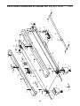
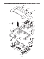
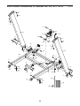
EXPLODED DRAWING . . . . . . . . . . . . . . . . . . . . . . . . . . . . . . . . . . . . . . . . . . . . . . . . . . . . . . . . . . . . . . . . . . . .24
ORDERING REPLACEMENT PARTS . . . . . . . . . . . . . . . . . . . . . . . . . . . . . . . . . . . . . . . . . . . . . . . . . .Back Cover
RECYCLING INFORMATION . . . . . . . . . . . . . . . . . . . . . . . . . . . . . . . . . . . . . . . . . . . . . . . . . . . . . . . . .Back Cover
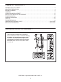
2
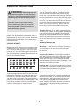
The warning decals shown here have been ap-
plied in the locations shown. If a decal is missing
or illegible, call the telephone number on the
front cover of this manual and request a free
replacement decal. Apply the decal in the loca-
tion shown.
Note: The decal may not be shown
at actual size.
WARNING DECAL PLACEMENT
PROFORM is a registered trademark of ICON IP, Inc.

3
1. Before beginning any exercise program, con-
sult your physician. This is especially impor-
tant for persons over the age of 35 or persons
with pre-existing health problems.
2. It is the responsibility of the owner to ensure
that all users of this treadmill are adequately
informed of all warnings and precautions.
3. Use the treadmill only as described.
4. Place the treadmill on a level surface, with at
least 8 ft. (2.4 m) of clearance behind it and 2
ft. (0.6 m) on each side. Do not place the
treadmill on any surface that blocks air open-
ings. To protect the floor or carpet from dam-
age, place a mat under the treadmill.
5. Keep the treadmill indoors, away from mois-
ture and dust. Do not put the treadmill in a
garage or covered patio, or near water.
6. Do not operate the treadmill where aerosol
products are used or where oxygen is being
administered.
7. Keep children under the age of 12 and pets
away from the treadmill at all times.
8. The treadmill should be used only by persons
weighing 286 lbs. (130 kg) or less.
9. Never allow more than one person on the
treadmill at a time.
10. Wear appropriate exercise clothes when
using the treadmill. Do not wear loose clothes
that could become caught in the treadmill.
Athletic support clothes are recommended for
both men and women.
Always wear athletic
shoes. Never use the treadmill with bare feet,
wearing only stockings, or in sandals.
11. When connecting the power cord (see page
11), plug the power cord into an earthed cir-
cuit. No other appliance should be on the
same circuit. When replacing the fuse, an
ASTA approved BS1362 type should be fitted
to the fuse carrier. A 13 amp fuse should be
used.
12. If an extension cord is needed, use only a 3-
conductor, 1mm
2
(14-gauge) cord that is no
longer than 1.5 m.
13. Keep the power cord away from heated sur-
faces.
14. Never move the walking belt while the power
is turned off. Do not operate the treadmill if
the power cord or plug is damaged, or if the
treadmill is not working properly. (See TROU-
BLESHOOTING on page 19 if the treadmill is
not working properly.)
15. Read, understand, and test the emergency
stop procedure before using the treadmill (see
HOW TO TURN ON THE POWER on page 13).
16. Never start the treadmill while you are stand-
ing on the walking belt. Always hold the
handrails while using the treadmill.
17. The treadmill is capable of high speeds.
Adjust the speed in small increments to avoid
sudden jumps in speed.
18. The pulse sensor is not a medical device.
Various factors, including the user's move-
ment, may affect the accuracy of heart rate
readings. The pulse sensor is intended only
as an exercise aid in determining heart rate
trends in general.
19. Never leave the treadmill unattended while it
is running. Always remove the key, unplug
the power cord, and switch the reset/off cir-
cuit breaker to the off position when the
treadmill is not in use. (See the drawing on
page 5 for the location of the circuit breaker.)
WARNING: To reduce the risk of serious injury, read all important precautions and in-
structions in this manual and all warnings on your treadmill before using your treadmill. ICON as-
sumes no responsibility for personal injury or property damage sustained by or through the use of
this product.
IMPORTANT PRECAUTIONS

4
20. Do not attempt to raise, lower, or move the
treadmill until it is properly assembled. (See
ASSEMBLY on page 6, and HOW TO FOLD
AND MOVE THE TREADMILL on page 17.)
You must be able to safely lift 45 lbs. (20 kg)
to raise, lower, or move the treadmill.
21. When folding or moving the treadmill, make
sure that the storage latch is fully closed.
22. Never insert any object into any opening on
the treadmill.
23. Inspect and properly tighten all parts of the
treadmill regularly.
24.
DANGER: Always unplug the power
cord immediately after use, before cleaning the
treadmill, and before performing the mainte-
nance and adjustment procedures described in
this manual. Never remove the motor hood un-
less instructed to do so by an authorized ser-
vice representative. Servicing other than the
procedures in this manual should be performed
by an authorized service representative only.
25. This treadmill is intended for in-home use
only. Do not use this treadmill in a commer-
cial, rental, or institutional setting.
SAVE THESE INSTRUCTIONS

5
Thank you for selecting the revolutionary PROFORM
®
STYLE 8000 treadmill. The STYLE 8000 treadmill of-
fers an impressive array of features designed to make
your workouts at home more enjoyable and effective.
And when you’re not exercising, the unique STYLE
8000 treadmill can be folded up, requiring less than half
the floor space of other treadmills.
For your benefit, read this manual carefully before
using the treadmill. If you have questions after read-
ing this manual, please see the front cover of this man-
ual. To help us assist you, note the product model
number and serial number before contacting us. The
model number and the location of the serial number
decal are shown on the front cover of this manual.
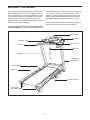
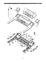
Before reading further, please familiarize yourself with
the parts that are labeled in the drawing below.
BEFORE YOU BEGIN
Handrail
Upright
Accessory Tray
Key/Clip
Reset/Off
Circuit Breaker
Walking Belt
Platform Cushion
Foot Rail
Rear Roller
Adjustment Bolts
Console
Book Holder
Pulse Sensor

ASSEMBLY
Assembly requires two persons. Set the treadmill in a cleared area and remove all packing materials. Do not
dispose of the packing materials until assembly is completed. Note: The underside of the treadmill walking belt is
coated with high-performance lubricant. During shipping, a small amount of lubricant may be transferred to the
top of the walking belt or the shipping carton. This is a normal condition and does not affect treadmill perfor-
mance. If there is lubricant on top of the walking belt, simply wipe off the lubricant with a soft cloth and a mild,
non-abrasive cleaner.
Assembly requires the included hex keys and your own Phillips screwdriver and
adjustable wrench .
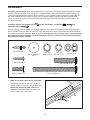
Use the drawings below to identify the assembly hardware. The number in parentheses below each drawing is
the key number of the part, from the PART LIST near the end of this manual. The number after the parentheses
is the quantity needed for assembly. Note: If a part is not in the parts bag, check to see if it is preattached to
one of the parts to be assembled. To avoid damaging plastic parts, do not use power tools for assembly.
Extra hardware may be included.
3/8" Nut (8)–3
1" Tek Screw (56)–4
Base Pad Spacer
(25)–2
3/4" Screw (10)–8
3/8" Star
Washer (9)–4
5/16" Star
Washer (7)–4
5/16" x 1" Bolt (5)–4
3/8" x 2" Bolt (4)–3
3/8" x 4" Bolt (6)–4
6
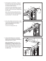
1. Make sure that the power cord is unplugged.
Remove the 3/8" Nut (8), the 3/8" x 2" Bolt (4),
and the shipping bracket (A) from the Base (80).
Repeat this step on the other side of the
treadmill.
Discard the shipping brackets. The
Nuts and Bolts will be used later.
80
4
A
8
1

7
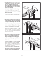
4. Identify the Right Upright (72) and the Right
Upright Spacer (74), which are marked with
stickers. Insert the Upright Wire (78) through the
Right Upright Spacer as shown.
See the inset drawing. Tie the wire tie in the
Right Upright (72) securely around the end of
the Upright Wire (78). With the help of a second
person, hold the Right Upright near the Base
(80). Then, pull the other end of the wire tie until
the Upright Wire is routed completely through
the Right Upright.
3. Attach a Base Wheel (81) with the 3/8" x 2" Bolt
(4) and the 3/8" Nut (8) that you removed in step
1. Do not overtighten the Nut; the Base
Wheel must turn freely.
Cut the tie off the Upright Wire (78).
78
Tie
4
8
3
81
80
78
72
74
78
4
Wire
Tie
72
78
Tie
2. With the help of a second person, carefully tip
the treadmill onto its left side. Partially fold the
Frame (53) so that the treadmill is more stable;
do not fully fold the Frame yet.
Cut the tie securing the Upright Wire (78) to the
Base (80). Locate the tie in the indicated hole in
the Base, and use the tie to pull the Upright Wire
out of the hole.
Attach a Base Pad (79) to the Base (80) in the
location shown with a Base Pad Spacer (25) and
a 1" Tek Screw (56). Then, attach another Base
Pad (79) with only a 1" Tek Screw (56).
80
56
53
79
2
79
56
78
Tie
Hole
25

8
6. With the help of a second person, carefully tip
the treadmill onto its right side. Partially fold the
Frame (53) so the treadmill is more stable;
do
not fully fold the Frame yet.
Attach a Base Pad (79) to the Base (80) in the
location shown with a Base Pad Spacer (25)
and a 1" Tek Screw (56). Then, attach another
Base Pad (79) with only a 1" Tek Screw (56).
Attach a Base Wheel (81) with the 3/8" x 2" Bolt
(4) and the 3/8" Nut (8) that you just removed in
step 1.
Do not overtighten the Nut; the Base
Wheel must turn freely.
6
80
81
53
4
8
79
56
79
25
56
7. With the help of a second person, hold a Bolt
Spacer (3) inside the lower end of the Left
Upright (71). Insert a 3/8" x 4" Bolt (6) with a
3/8" Star Washer (9) into the Left Upright and
the Bolt Spacer. Repeat this step with a second
Bolt Spacer (3), 3/8" x 4" Bolt (6), and 3/8" Star
Washer (9).
Orient the Left Upright (71) and the Left Upright
Spacer (73) as shown. Hold the Left Upright
Spacer and the Left Upright against the Base
(80). Finger tighten the 3/8" x 4" Bolts (6);
do
not fully tighten the Bolts yet.
Press a Base Endcap (75) into the Base (80).
With the help of a second person, tip the tread-
mill so that the Base (80) is flat on the floor.
73
71
6
80
3
3
75
9
7
5. Hold a Bolt Spacer (3) inside the lower end of
the Right Upright (72). Insert a 3/8" x 4" Bolt (6)
with a 3/8" Star Washer (9) into the Right
Upright and the Bolt Spacer. Repeat this step
with a second Bolt Spacer (3), 3/8" x 4" Bolt (6),
and 3/8" Star Washer (9).
Hold the Right Upright Spacer (74) and the
Right Upright (72) against the Base (80).
Be
careful not to pinch the Upright Wire (78).
Finger tighten the 3/8" x 4" Bolt (6); do not fully
tighten the Bolts yet.
Press a Base Endcap (75) into the Base (80).
74
72
78
9
75
3
3
6
5
80

9
9. Insert the Book Rack (84) into the console as-
sembly; it may be helpful to rock the Book Rack
up and down as you insert it. Attach the Book
Rack with eight 3/4" Screws (10);
start all eight
Screws and then tighten them.
See steps 5 and 7.
Tighten the 3/8" x 4" Bolts
(6).
10
10
84
Console Assembly
10
9
10. If necessary, press the Left Tray (86) and the
Right Tray (85) into the top of the console as-
sembly.
Console
Assembly
86
85
10
8. Have a second person hold the console assem-
bly near the Right Upright (72). Remove the wire
tie from the Upright Wire (78).
Connect the Upright Wire (78) to the console
wire.
See the inset drawing. The connectors
should slide together easily and snap into
place.
If they do not, turn one connector and try
again. IF THE CONNECTORS ARE NOT CON-
NECTED PROPERLY, THE CONSOLE MAY
BE DAMAGED WHEN THE POWER IS
TURNED ON.
Then, insert the connectors into
the Right Upright (72).
Set the console assembly on the Right Upright
(72) and the Left Upright (not shown). Attach the
console assembly with four 5/16" x 1" Bolts (5)
and four 5/16" Star Washers (7) (only two are
shown);
start all four Bolts and then tighten
them.
5
72
7
78
Console
Assembly
Console
Wire
Wire Tie
8
5
7
78
Console
Wire

10
13. Make sure that all parts are properly tightened before you use the treadmill. If there are sheets of clear
plastic on the treadmill decals, remove the plastic. To protect the floor or carpet, place a mat under the tread-
mill. Keep the included hex key in a secure place; the hex key is used to adjust the walking belt (see pages
20 and 21).
12. Raise the Frame (53) to the position shown.
Have a second person hold the Frame until
this step is completed.
Orient the Latch Assembly (55) so that the large
barrel and the Latch Knob (54) are in the posi-
tions shown. Attach the Latch Bracket (68) to the
bracket on the Base (80) with two 3/8" x 2" Bolts
(4) and two 3/8" Nuts (8).
Attach the upper end of the Latch Assembly (55)
to the bracket on the Frame (53) with a 3/8" x 2"
Bolt (4) and a 3/8" Nut (8). Note: It may be nec-
essary to move the Frame back and forth to
align the Latch Assembly with the bracket.
Lower the Frame (53) (see HOW TO LOWER
THE TREADMILL FOR USE on page 18).
55
8
8
Large
Barrel
68
80
4
53
12
4
54
11. Identify the Latch Assembly (55). Remove the
tie from the end of the tube. Make sure that the
sleeve has been slid over hole 1 and that the
Latch Knob (54) is locked into hole 1.
Pull on
the sleeve to make sure that it is locked into
place.
11
54
Sleeve
Hole 1
Tube
55

11
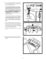
THE PRE-LUBRICATED WALKING BELT
Your treadmill features a walking belt coated with high-performance lubricant. IMPORTANT: Never apply sili-
cone spray or other substances to the walking belt or the walking platform. Such substances will deterio-
rate the walking belt and cause excessive wear.
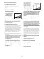
HOW TO PLUG IN THE POWER CORD
This product must be earthed.
If it should malfunction or break
down, earthing provides a path of least resistance for electric cur-
rent to reduce the risk of electric shock. This product is equipped
with a power cord having an equipment-earthing conductor and an
earthing plug.
Important: If the power cord is damaged, it must
be replaced with a manufacturer-recommended power cord.
See drawing 1. Plug the indicated end of the power cord into the
socket on the treadmill.
See drawing 2. Press the pins on the power cord into the metal clips
in the adapter as shown. Close the adapter cover over the end of the
power cord and tighten the screw in the adapter.
Important: Make
sure that the adapter cover is secure and the screw has been
tightened before using the power cord.
See drawing 3. Plug the power cord into an appropriate outlet that is
properly installed and earthed in accordance with all local codes and
ordinances. Important: The treadmill is not compatible with
RCD-equipped outlets.
OPERATION AND ADJUSTMENT
DANGER: Improper connection of the equipment-earthing conductor can result in an in-
creased risk of electric shock. Check with a qualified electrician or serviceman if you are in doubt as
to whether the product is properly earthed. Do not modify the plug provided with the product—if it will
not fit the outlet, have a proper outlet installed by a qualified electrician.
Socket on Treadmill
Metal
Clips
1
2
Pins
Screw
Adapter
Outlet
3
Adapter
Cover

12
K
m
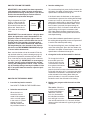
FEATURES OF THE CONSOLE
The treadmill console offers an impressive array of
features designed to make your workouts more effec-
tive and enjoyable.
When the manual mode of the console is selected, you
can change the speed and incline of the treadmill with
the touch of a button. As you exercise, the console will
display instant exercise feedback. You can even mea-
sure your heart rate using the handgrip pulse sensor or
the optional chest pulse sensor.
In addition, the console offers twelve preset workouts.
Each workout automatically controls the speed and in-
cline of the treadmill as it guides you through an effec-
tive exercise session.
To use the manual mode of the console, follow the
steps beginning on page 13. To use a preset work-
out, see page 15.
IMPORTANT: If there is a sheet of clear plastic on
the face of the console, remove the plastic. To pre-
vent damage to the walking platform, wear clean
athletic shoes while using the treadmill. The first
time you use the treadmill, observe the alignment of
the walking belt, and center the walking belt if nec-
essary (see page 21).
Note: The console can display speed and distance in
either kilometers or miles. To find out which unit of
measurement is selected or to change the unit of mea-
surement, see THE INFORMATION MODE on page
16. For simplicity, all instructions in this section refer to
kilometers.
Clip
Key
CONSOLE DIAGRAM

13
HOW TO TURN ON THE POWER
IMPORTANT: If the treadmill has been exposed to
cold temperatures, allow it to warm to room tem-
perature before turning on the power. If you do not
do this, the console displays or other electrical
components may become damaged.
Plug in the power cord (see
page 11). Next, locate the
reset/off circuit breaker on
the treadmill frame near the
power cord. Switch the cir-
cuit breaker to the reset po-
sition.
IMPORTANT: The console features a display demo
mode, designed to be used if the treadmill is dis-
played in a store. If the displays light as soon as
you plug in the power cord and switch the circuit
breaker to the reset position, the demo mode is
turned on. To turn off the demo mode, hold down
the Stop button for a few seconds. If the displays
remain lit, see THE INFORMATION MODE on page
16 to turn off the demo mode.
Next, stand on the foot rails of the treadmill. Find the
clip attached to the key (see the drawing on page 12)
and slide the clip onto the waistband of your clothes.
Then, insert the key into the console. After a moment,
the displays will light.
IMPORTANT: In an emergency
situation, the key can be pulled from the console,
causing the walking belt to slow to a stop. Test the
clip by carefully taking a few steps backward; if the
key is not pulled from the console, adjust the posi-
tion of the clip.
HOW TO USE THE MANUAL MODE
1. Insert the key into the console.
See HOW TO TURN ON THE POWER above.
2. Select the manual mode.
When the key is in-
serted, the manual
mode will be selected
and a track will appear
in the matrix. If a preset
workout has been
selected, remove the
key and then reinsert it.
3. Start the walking belt.
To start the walking belt, press the Start button, the
Go button, the speed increase button, or one of the
speed buttons numbered 4 through 20.
If the Start button, the Go button, or the speed in-
crease button is pressed, the walking belt will begin
to move at 2 km/h. As you exercise, change the
speed of the walking belt as desired by pressing
the speed increase and decrease buttons. Each
time a button is pressed, the speed setting will
change by 0.1 km/h; if a button is held down, the
speed setting will change in increments of 0.5
km/h. Note: After the buttons are pressed, it may
take a moment for the walking belt to reach the se-
lected speed setting.
If one of the numbered speed buttons is pressed,
the walking belt will gradually increase in speed until
it reaches the selected speed setting.
To stop the walking belt, press the Stop button. To
restart the walking belt, press the Start button, the
Go button, the speed increase button, or one of the
speed buttons numbered 4 through 20.
4. Change the incline of the treadmill as desired.
To change the incline of
the treadmill, press the
Incline increase and de-
crease buttons or one of
the numbered incline but-
tons. Each time you
press the incline increase or decrease button, the
incline will change by 0.5%. If you press one of the
numbered incline buttons, the treadmill will adjust
to the selected incline setting. Note: After you
press the buttons, it may take a moment for the
treadmill to reach the selected incline setting.
5. Monitor your progress with the matrix and the
displays.
The matrix
—When the
manual mode is selected,
the matrix will display a
400 meter (1/4-mile)
track. As you exercise,
the indicators around the
track will light in succes-
sion until the entire track is lit. The track will then
darken and the indicators will again begin to light in
succession.
Reset
Position

14
Time display—When
the manual mode is se-
lected, this display will
show the elapsed time.
When a workout is se-
lected, the display will
show the time remaining in the workout rather than
the elapsed time.
Distance/Incline dis-
play
—This display
shows the distance that
you have walked or run.
Note: Each time the in-
cline changes, the dis-
play will show the incline setting for several sec-
onds.
Calories/Pulse
display
—This display
shows the approximate
number of calories you
have burned. The dis-
play will also show your
heart rate when you use the handgrip pulse sen-
sor.
Speed display—This
display shows the
speed of the walking
belt.
To reset the displays, press the Stop button, re-
move the key, and then reinsert the key.
6. Measure your heart rate if desired.
You can measure your heart rate using either the
handgrip pulse sensor or the optional chest pulse
sensor (see page 16 for information about the op-
tional chest pulse sensor). Note: If you hold the
handgrip pulse sensor and wear the chest pulse
sensor at the same time, the console will not dis-
play your heart rate accurately.
Before using the
handgrip pulse
sensor, first re-
move the sheets
of clear plastic
from the metal
contacts on the
pulse bar. In ad-
dition, make sure
that your hands are clean.
To use the handgrip pulse sensor,
stand on the
foot rails and hold the pulse bar with your palms
on the metal contacts. Avoid moving your
hands
. When your pulse is detected, two dashes
(– –) will appear in the Calories/Pulse display, and
then your heart rate will be shown. For the most
accurate heart rate reading, continue to hold
the contacts for about 15 seconds.
7. When you are finished exercising, remove the
key from the console.
Step onto the foot rails, press the Stop button, and
adjust the incline of the treadmill to the lowest
setting. The incline must be at the lowest setting
or you may damage the treadmill when you fold
it to the storage position. Next, remove the key
from the console and put it in a secure place.
When you are finished using the treadmill, switch
the reset/off circuit breaker to the “off” position and
unplug the power cord.
IMPORTANT: If you do
not do this, the treadmill’s electrical compo-
nents may wear prematurely.
Contacts

15
HOW TO USE A PRESET WORKOUT
1. Insert the key into the console.
See HOW TO TURN ON THE POWER on
page 13.
2. Select a preset workout.
To select a preset workout, press the Select
Workout button repeatedly.
When a preset workout
is selected, the mini-
mum speed setting of
the workout will appear
in the Distance/Incline
display, the maximum
speed setting will ap-
pear in the Calories/Pulse display, and the workout
time will appear in the Time display. In addition, a
profile of the speed settings of the workout will
scroll across the matrix.
3. Customize your workout if desired.
You can change the length of the workout, the min-
imum speed setting of the workout, and/or the
maximum speed setting of the workout before you
begin. To customize your workout, press the Set
Time, the Set Min Speed, and/or the Set Max
Speed increase and decrease buttons. The new
workout settings will appear in the displays.
4. Press the Start button or the Go button to start
the workout.
A moment after the button is pressed, the treadmill
will automatically adjust to the first speed and in-
cline settings of the workout. Hold the handrails
and begin walking.
Each workout is divided into 30 one-minute seg-
ments, unless you have changed the length of the
program (see step 3). One speed setting and one
incline setting are programmed for each segment.
Note: The same speed setting and/or incline set-
ting may be programmed for two or more consecu-
tive segments.
During the workout, the
profile will show your
progress. The flashing
segment of the profile
represents the current
segment of the workout.
The height of the flashing
segment indicates the
speed setting for the cur-
rent segment. At the end of each segment, a series
of tones will sound and the next segment of the pro-
file will begin to flash. If a different speed or incline
setting is programmed for the next segment, the
speed or incline setting will flash in the display to
alert you.
The workout will continue in this way until the last
segment of the profile flashes in the display and
the last segment ends. The walking belt will then
slow to a stop.
If the speed or incline setting is too high or too low
at any time during the workout, you can manually
override the setting by pressing the speed or incline
buttons.
Note: When the next segment of the
workout begins, the treadmill will automatically
adjust to the speed and incline settings for the
next segment.
To stop the workout at any time, press the Stop
button. To restart the workout, press the Start but-
ton or the Go button. The walking belt will begin to
move at 2 km/h. When the next segment of the
workout begins, the treadmill will automatically ad-
just to the speed and incline settings for the next
segment.
5. Monitor your progress with the matrix and the
displays.
See step 5 on pages 13 and 14.
6. Measure your heart rate if desired.
See step 6 on page 14.
7. When you are finished exercising, remove the
key from the console.
See step 7 on page 14.
Current Segment

16
THE INFORMATION MODE
The console features an information mode that keeps
track of the total distance that the walking belt has
moved and the total number of hours that the treadmill
has been used. The information mode also allows you
to switch the console from kilometers to miles. In addi-
tion, the information mode allows you to turn on and
turn off the display demo mode.
To select the information mode, hold down the Stop
button while inserting the key into the console and then
release the Stop button. When the information mode is
selected, the following information will be shown:
An “M” for metric kilometers
or “E” for English miles will
appear in the Calories/Pulse
display. Press the speed in-
crease button to change the
unit of measurement if de-
sired.
The Distance/Incline display
will show the total number of
kilometers (or miles) that the
walking belt has moved.
The Time display will show
the total number of hours
the treadmill has been used.
Note: The console features a display demo mode, de-
signed to be used if the treadmill is displayed in a
store. While the demo mode is turned on, the console
will function normally when you plug in the power cord,
switch the circuit breaker to the reset position, and in-
sert the key into the console. However, when you re-
move the key, the displays will remain lit, although the
buttons will not function. If the demo mode is turned
on, a “d” will appear in the speed display while the in-
formation mode is selected. To turn on or turn off the
demo mode, press the speed decrease button.
To exit the information mode, remove the key from the
console.
THE OPTIONAL CHEST PULSE SENSOR
An optional chest pulse sensor offers hands-free oper-
ation as it tracks your heart rate during your workouts.
To purchase the optional chest pulse sensor, call
the telephone number on the front cover of this
manual.
If you purchase the optional chest pulse sensor,
follow the steps below to install the receiver in-
cluded with the chest pulse sensor.
1. Make sure that the power cord is unplugged.
Remove the indicated 1/2" Screws (1) and the
Access Door (93) from the Console Back (91).
2. Connect the wire on the receiver (A) to the indi-
cated wire extending from the Console Back (91).
Hold the receiver so the small cylinder is ori-
ented as shown and is facing the Console
Back.
Attach the receiver to the plastic posts on
the Access Door (93) with the two included small
screws.
3.
Make sure that no wires are pinched. Reattach
the Access Door (93) with the 1/2" Screws (1).
Discard the other wires included with the receiver.
A
91
Small
Cylinder
1
93
Wire
Small
Screws

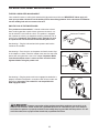
17
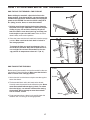
HOW TO FOLD AND MOVE THE TREADMILL
HOW TO FOLD THE TREADMILL FOR STORAGE
Before folding the treadmill, adjust the incline to the
lowest position. If you do not do this, you may damage the
treadmill when you fold it. Remove the key and unplug the
power cord. CAUTION: You must be able to safely lift 45
lbs. (20 kg) to raise, lower, or move the treadmill.
1. Hold the metal frame firmly in the location shown by
the arrow at the right. CAUTION: To decrease the pos-
sibility of injury, do not lift the frame by the plastic
foot rails. Make sure to bend your legs and keep your
back straight as you raise the frame.
Raise the frame
about halfway to the vertical position.
2. Raise the frame until the latch knob locks into the storage
position.
Make sure that the latch knob is locked in
the storage position.
To protect the floor or carpet from damage, place a
mat under the treadmill. Keep the treadmill out of di-
rect sunlight. Do not leave the treadmill in the stor-
age position in temperatures above 85° F (30° C).
HOW TO MOVE THE TREADMILL
Before moving the treadmill, convert the treadmill to the stor-
age position as described above. Make sure that the latch
knob is locked in the storage position.
1. Hold a handrail and the frame and place one foot against
one of the wheels.
2. Tilt the treadmill back until it rolls freely on the wheels.
Carefully move the treadmill to the desired location.
Never
move the treadmill without tipping it back. To reduce
the risk of injury, use extreme caution while moving
the treadmill. Do not attempt to move the treadmill
over an uneven surface.
3. Place one foot against a wheel, and carefully lower the
treadmill until it is resting in the storage position.
Latch Knob
Frame
Base
Handrail
Frame
Wheels

18
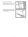
HOW TO LOWER THE TREADMILL FOR USE
1. Hold the upper end of the treadmill with your right hand.
Pull the latch knob to the left and hold it. It may be nec-
essary to push the frame forward as you pull the knob to
the left. Pivot the frame downward and release the latch
knob.
2.
Hold the metal frame firmly with both hands and lower it
to the floor. CAUTION: Do not grip only the plastic foot
rails or drop the frame to the floor. Bend your legs and
keep your back straight.
Latch Knob
Frame

19
TROUBLESHOOTING
Most treadmill problems can be solved by following the simple steps below. Find the symptom that
applies, and follow the steps listed. If further assistance is needed, call the telephone number listed on
the back cover of this manual.
PROBLEM: The power does not turn on
SOLUTION:
a. Make sure that the power cord is plugged into a properly earthed outlet. (See page 11.) If an ex-
tension cord is needed, use only a 3-conductor, 1 mm
2
(14-gauge) cord that is no longer than 1.5
m (5 ft.). Important: The treadmill is not compatible with RCD-equipped outlets.
b. After the power cord has been plugged in, make sure that the key is inserted into the console.
c. Check the reset/off circuit breaker located on the
treadmill frame near the power cord. If the switch
protrudes as shown, the circuit breaker has
tripped. To reset the circuit breaker, wait for five
minutes and then press the switch back in.
PROBLEM: The power turns off during use
SOLUTION:
a. Check the reset/off circuit breaker (see the drawing above). If the circuit breaker has tripped, wait
for five minutes and then press the switch back in.
b. Make sure that the power cord is plugged in. If the power cord is plugged in, unplug it, wait for
five minutes, and then plug it back in.
c. Remove the key from the console. Reinsert the key into the console.
d. If the treadmill still will not run, please see the front cover of this manual.
PROBLEM: The incline of the treadmill does not change correctly
SOLUTION: a. With the key in the console, press one of the Incline buttons. While the incline is changing, re-
move the key.
After a few seconds, re-insert the key. The treadmill will automatically rise to the
maximum incline level and then return to the minimum level. This will recalibrate the incline system.
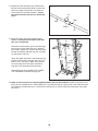
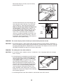
PROBLEM: The displays of the console do not function properly
SOLUTION: a. Remove the key from the console and UNPLUG
THE POWER CORD.
With the help of a second
person, carefully tip the Uprights (71, 72) down.
There may be two Hood Screws (102) in the bottom
of the Belly Pan (66). If there are, remove them.
Then, raise the Uprights. Note: A Phillips screw-
driver with a shaft at least 5 in. (13 cm) long is re-
quired.
Tripped
Reset
c
102
66
102
72
71
a

20
Remove the three 3/4" Screws (10) and carefully
pivot the Hood (57) off.
Locate the Reed Switch (64) and the Magnet (42)
on the left side of the Pulley (43). Turn the Pulley
until the Magnet is aligned with the Reed Switch.
Make sure that the gap between the Magnet and
the Reed Switch is about 1/8 in. (3 mm). If nec-
essary, loosen the Reed Switch Screw (12), move
the Reed Switch slightly, and then retighten the
Screw. Then, reattach the Hood (not shown). If
necessary, tip down the Uprights (not shown), reat-
tach the Hood Pan Screws (not shown), and raise
the Uprights. Run the treadmill for a few minutes to
check for a correct speed reading.
PROBLEM: The console displays remain lit when you remove the key from the console
SOLUTION:
a. The console features a display demo mode, designed to be used if the treadmill is displayed in a
store. If the displays remain lit when you remove the key, the demo mode is turned on. To turn off
the demo mode, hold down the Stop button for a few seconds. If the displays are still lit, see THE
INFORMATION MODE on page 16 to turn off the demo mode.
PROBLEM: The walking belt slows when walked on
SOLUTION:
a. If an extension cord is needed, use only a 3-conductor, 1 mm
2
(14-gauge) cord that is no longer
than 1.5 m (5 ft.).
b. If the walking belt is overtightened, treadmill perfor-
mance may decrease and the walking belt may be-
come damaged. Remove the key and
UNPLUG
THE POWER CORD. Using the hex key, turn both
rear roller bolts counterclockwise, 1/4 of a turn.
When the walking belt is properly tightened, you
should be able to lift each edge of the walking belt
2 to 3 in. (5 to 7 cm) off the walking platform. Be
careful to keep the walking belt centered. Then,
plug in the power cord, insert the key, and run the
treadmill for a few minutes. Repeat until the walking
belt is properly tightened.
c. If the walking belt still slows when walked on, see the front cover of this manual.
Top
View
42
12
64
1/8 in.
43
Rear Roller Bolts
2–3 in.
b
57
10
Page is loading ...
Page is loading ...
Page is loading ...
Page is loading ...
Page is loading ...
Page is loading ...
Page is loading ...
Page is loading ...
-
 1
1
-
 2
2
-
 3
3
-
 4
4
-
 5
5
-
 6
6
-
 7
7
-
 8
8
-
 9
9
-
 10
10
-
 11
11
-
 12
12
-
 13
13
-
 14
14
-
 15
15
-
 16
16
-
 17
17
-
 18
18
-
 19
19
-
 20
20
-
 21
21
-
 22
22
-
 23
23
-
 24
24
-
 25
25
-
 26
26
-
 27
27
-
 28
28


Pro-Form 995 ZLT PETL71707.2 User manual
- Category
- Treadmills
- Type
- User manual
- This manual is also suitable for
Ask a question and I''ll find the answer in the document
Finding information in a document is now easier with AI
Related papers
-
ProForm PATL40707.0 User manual
-
-
Pro-Form 1000 Lt Treadmill User manual
-
-
-
-
-
-
-
Other documents
-
NordicTrack NETL99809.1 User manual
-
-
-
-
-
-
-
-
-
NordicTrack A2550 User manual