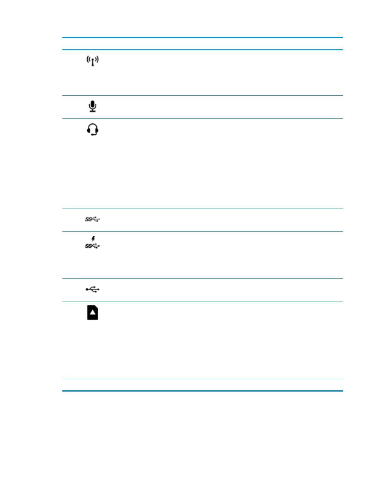
Component Description
(3) Wireless light
●
On: An integrated wireless device, such as a wireless local area network
(WLAN) device and/or a Bluetooth® device, is on.
●
O: All integrated wireless devices are o.
NOTE: On some products, the wireless light is amber when all wireless devices
are o.
(4) Audio-in (microphone) jack Connects an optional computer headset microphone, stereo array microphone,
or monaural microphone.
(5) Audio-out (headphone)/
Audio-in (microphone)
combo jack
Connects optional powered stereo speakers, headphones, earbuds, a headset, or
a television audio cable. Also connects an optional headset microphone. This
jack does not support optional standalone microphones.
WARNING! To reduce the risk of personal injury, adjust the volume before
putting on headphones, earbuds, or a headset. For additional safety
information, refer to the Regulatory, Safety, and Environmental Notices.
To access this guide:
▲ Select the Start button, select All apps, select HP Help and Support, and
then select HP Documentation.
NOTE: When a device is connected to the jack, the computer speakers are
disabled.
(6) USB 3.0 port Connects an optional USB device, such as a keyboard, mouse, external drive,
printer, scanner or USB hub.
(7) USB 3.0 charging
(powered) port
Connects an optional USB device, such as a keyboard, mouse, external drive,
printer, scanner or USB hub. Standard USB ports will not charge all USB devices
or will charge using a low current. Some USB devices require power and require
you to use a powered port.
NOTE: USB charging ports can also charge select models of cell phones and
MP3 players, even when the computer is o.
(8) USB Type-C ports (2) Connect USB devices with a Type-C connector.
(9) Memory card reader Reads optional memory cards that enable you to store, manage, share, or access
information.
To insert a card:
1. Hold the card label-side up, with connectors facing the computer.
2. Insert the card into the memory card reader, and then press in on the card
until it is rmly seated.
To remove a card:
▲ Press in on the card, and then remove it from the memory card reader.
(10) Drive cage latch Locks the drive cage.
Right 5


