Soundstream HR 2 User manual
- Category
- Musical Equipment
- Type
- User manual
This manual is also suitable for

HR 2
HR 4
Owner’s Manual
and
Installation Guide
HUMAN REIGN

You now own the Soundstream Human Reign amplifier, the product of an
uncompromising design and engineering philosophy. Your Soundstream Human
Reign amplifier will outperform any other amplifier in the world.
To maximize the performance of your system, we recommend that you
thoroughly acquaint yourself with its capabilities and features. Please retain this
manual and your sales receipt for future reference.
Soundstream amplifiers are the result of American innovation and the highest
quality control standards. When properly installed, they will provide you with
many years of listening pleasure. Should your amplifier ever need service or
replacement due to theft, please record the following information which will help
protect your investment.
Congratulations!
Model and Serial #
Dealer's Name
Date of Purchase
Installation Shop
Installation Date
2
C A U T I O N !
Prolonged listening at extremely high levels may result in hearing loss.
Even though your new Soundstream Human Reign amplifier sounds
better than anything you've ever heard, exercise caution to prevent
hearing damage.

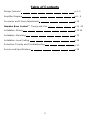
Design Features
Amplifier Diagram
Crossover and Phase Adjustments
Hawkins Bass Control™ Theory and Use
Installation: Wiring
Installation: Mounting
Installation: Level Setting
Protection Circuitry and Troubleshooting
Service and Specifications
p 4 -5
p 6 - 9
p 10
p 11 -12
p 13-14
p 15
p 16
p 17
p 18
Table of Contents
3

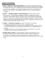
DESIGN FEATURES
RUBI™(Rapid-Use Branched Impulse) This new proprietary power supply
topology eliminates “power sags” during low frequency reproduction by rapidly
increasing the duty cycle, stabilizing the power supply and allowing it to deliver
the power required then reproducing low frequencies. Also, greater reserve
gate power is stored for low voltage conditions that occur during extreme
conditions.
STACT™(STabilized Apex Current Topology) Reduces power supply
stress by 50%. Typical designs degrade the stereo image due to phase
reversal of even-order harmonic distortion that occurs between the inverted
channels. In the STACT design, inversion is done at the power amplifier drive
stage. Since the fully symmetrical power amplifier produces no even-harmonic
distortion itself and all preamplifier circuitry is run completely in-phase, no even
harmonic distortion phase reversal occurs.
Trident™ Protection Topology provides three types of protection:
1. Output protection against short circuits or improper loads.
2. Ground fault detection: Shuts down the amplifier when a significant voltage
(>5 Volts) fluctuation occurs between electrical (turn-on lead)and battery
ground.
3. Thermal Protection: Puts the amplifier into thermal rollback or shuts the
amplifier down in extreme thermal conditions.
Hawkins Bass Control - Fully adjustable subwoofer equalization circuit
providing frequency and boost(“Q”) adjustment for optimum subwoofer
performance. A frequency tracking subsonic filter protects woofers from
potentially harmful low frequency information and maximizes output in a usable
range.
4

Harmonic Bass Alignment™ The 2nd and 3rd order harmonic peaks are
critically aligned to fundamental peaks at low frequencies. This produces
tighter, more accurate bass reproduction.
Drive Delay II™ Amplifier section powers up 2 to 3 seconds after the power
supply eliminating turn-on pops. The turn off process is reversed:
Amplifier section turns off first, followed by the power supply.
Output Clipping Indicators indicate clipping on the output stage of the
amplifier. Monitoring the clipping indicators allows the user to achieve
maximum Sound Pressure Level without clipping the amplifier.
Dynamically Optimized power Grid™ Power grid is evenly distributed
between primary and secondary power supplies, providing greater dynamics
and improved RF filtering.
Chassisink™ All transistors are ideally located and sandwiched between the
circuit board and the heatsink to provide cool efficient amplifier operation.
Differentially Balanced RCA Input eliminates ground loop related noise in
the audio.
Continuously Variable Crossover Network : 12dB/Octave highpass
crossover variable from 50 to 200 Hz and 24dB/Octave lowpass crossover
variable from 40 to 160 Hz.
Flexible Input Level Control allows 300 mV to 5 V input sensitivity.
Symmetrical Discrete Balanced Class A Drive Boards auto-adjust for linear
performance while driving low impedance loads.
Removable Front Spoiler allows for stealth installation of RCA, Balanced
Line, Speaker and Power wiring.
5

6
Front View
Top View
- HR 2 -

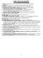
1. +12V - Connected to a fuse or circuit breaker, then to the battery’s positive
terminal.
2. GND - Main ground connection. Bolt to a clean chassis point in the vehicle.
3. REMOTE - Remote turn - on input from the head unit. Accepts +12V.
4. Speaker connection Terminal - Speaker connections for satellite CH1&2.
5. Hawkins Bass Control “Boost” Adjustment - Varies from 0 to + 9 dB of
boost when the Hawkins Bass Control circuit is engaged.
6. Subsonic/Hawkins Bass Control Adjustment - Frequency adjustment
control for the Hawkins Bass Control filter or the Sub Sonic filter.
7. Low Pass Filter Control Adjustment- Frequency adjustment control for the
Low Pass Filter for CH1&2 sum X-OVER.
8. High Pass Filter Control Adjustment- Frequency adjustment control for the
High Pass Filter for satellite CH1&2.
9. Input Levels - Input level control variable from 300mV to 5V.
10. RCA Inputs - 1&2 channel RCA inputs.
11. BALANCED Signal Input Connector - Channels 1 & 2 ; 6-pin Balanced signal input
connector for use with the Soundstream BLT Balanced Line Transmitter.
12. Line out - Line level RCA output to drive an external amplifier.
13. Power LED - Indicates amplifier power.
14. Phase Switch - Adjusts the speaker phase to either 0 or 180 degrees.
15. Subsonic/Hawkins Bass Control Switch - Selectable subwoofer enhancement circuit.
Select “SUB SONIC” to engage the Sub Sonic filter with no boost. Use the knob indicated
by callout #6 to set the frequency: 13- 30Hz. Select “Hawkins Bass Control” to engage the
Sub Sonic filter with available boost. Use the knob indicated by callout #6 to set the
frequency: 30 Hz to 70 Hz.
16.ST/MO(2)/LP Switch - “MONO” for bridge mono operation with a single input signal
(Channel 2 only). “SUM” for bridged mono operation summing two input signals (1CH and
2CH). “ST” for normal stereo operation.
17. High Pass X-OVER Switch - (Channels 1&2)Select”IN” for use with the internal crossover
or “OUT” for use with external crossover.
18. Mid-Bass/Midrange Select Switch - Selectable mid-bass “LOW” or midrange frequency
control “HIGH” operation.
19. Line output Switch - Select “Full 1.2” (Channel 1.2 full range), “1.2 TRACKING LP”(use
the knob or switch indicated by call out #8, #18) “1.2 LP SUM” (use the sum CH1.2)
Function for the RCA out put.
20. Channel Balanced / Unbalanced Input Selector Switch - Select “Balanced” to use the 6
pin Balanced signal input. Select “Unbalanced” to use the RCA signal inputs.
21. Input Overload Indicators - Indicates the signal input level or input gain level is too high.
KEY TO CALLOUTS
7


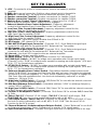
1. +12V - Connected to a fuse or circuit breaker, then to the battery’s positive
terminal.
2. GND - Main ground connection. Bolt to a clean chassis point in the vehicle.
3. REMOTE - Remote turn - on input from the head unit. Accepts +12V.
4. Speaker connection Terminal - Speaker connections for satellite CH1&2.
5. Speaker connection Terminal - Speaker connections for satellite CH3&4.
6. Hawkins Bass Control “Boost” Adjustment - Varies from 0 to + 9 dB of
boost when the Hawkins Bass Control circuit is engaged.
7. Subsonic/Hawkins Bass Control Adjustment - Frequency adjustment
control for the Hawkins Bass Control filter or the Sub Sonic filter.
8. Low Pass Filter Control Adjustment- Frequency adjustment control for the
Low Pass Filter for CH3&4 sum X-OVER.
9. High Pass Filter Control Adjustment- Frequency adjustment control for the
High Pass Filter for satellite CH1&2.
10. High Pass Filter Control Adjustment- Frequency adjustment control for the
High Pass Filter for satellite CH3&4.
11. Input Levels - Input level control variable from 300mV to 5V.
12. RCA Inputs - 1&2 channel RCA inputs.
13. BALANCED Signal Input Connector - Channels 1 & 2 ; 6-pin Balanced signal input
connector for use with the Soundstream BLT Balanced Line Transmitter.
14. RCA Inputs - 3&4 channel RCA inputs.
15. BALANCED Signal Input Connector - Channels 3 & 4 ; 6-pin Balanced signal input
connector for use with the Soundstream BLT Balanced Line Transmitter.
16. Line out - Line level RCA output to drive an external amplifier.
17. Power LED - Indicates amplifier power.
18. Phase Switch - Adjusts the speaker phase to either 0 or 180 degrees.
19.ST/MO(2)/LP Switch - “MONO” for bridge mono operation with a single input signal
(Channel 2 only). “SUM” for bridged mono operation summing two input signals (1CH and
2CH). “ST” for normal stereo operation.
20. ST/MO(3)/LP Switch - “MONO” for bridge mono operation with a single input signal
(Channel 4 only). “SUM” for bridged mono operation summing two input signals (3CH and
4CH). “ST” for normal stereo operation.
21. Subsonic/Hawkins Bass Control Switch - Selectable subwoofer enhancement circuit.
Select “SUB SONIC” to engage the Sub Sonic filter with no boost. Use the knob indicated
by callout #7 to set the frequency: 13- 30Hz. Select “Hawkins Bass Control” to engage the
Sub Sonic filter with available boost. Use the knob indicated by callout #7 to set the
frequency: 30 Hz to 70 Hz.
22. High Pass X-OVER Switch - (Channels 1&2)Select”IN” for use with the internal crossover
or “OUT” for use with external crossover.
23. Mid-Bass/Midrange Select Switch - Selectable mid-bass “LOW” or midrange frequency
control “HIGH” operation.
24. High Pass X-OVER Switch - (Channels 3&4) Select “IN” for use with the internal crossover
or “OUT” for use with external crossover.
25. CH3&4 Fill De-emphasis Switch - (Channels 3&4) Select “IN” to activate 6dB/Octave filter
@ 7kHz.
26. Select “Full 1.2” (Channel 1.2 full range), “Full 3.4” (Channel 3,4 full range), “1.2
TRACKING LP” (use the knob or switch indicated by call out #9, #23)
27. Line output Switch - Select “Full 1.2” (Channel 1.2 full range), “1.2 TRACKING LP”(use
the knob or switch indicated by call out #9, #23) “3.4 LP SUM” (use the sum CH3.4)
Function for the RCA out put.
28. Channel Balanced / Unbalanced Input Selector Switch - Select “Balanced” to use the 6
pin Balanced signal input. Select “Unbalanced” to use the RCA signal inputs.
29. Input Overload Indicators - Indicates the signal input level or input gain level is too high.
KEY T
O CALLOUTS
9

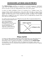
CROSSOVER & PHASE ADJUSTMENTS
The Human Reign amplifiers incorporate an on-board staggered electronic
cross-over. No external electronic crossover is necessary. The low pass portion
of the crossover can be set independently of the rest of the system.
In many car audio installations, there is a tendency for a ”midbass boom.” Be-
cause of their interior dimensions, most cars will resonate or ring at these
midbass frequencies. If we design the system so there is reduced output in this
region, the final response is very smooth and natural sounding. The HUMAN
Reign has an always on low pass crossover that is independently variable from
40 to 160 Hz at 24 dB/Octave.
For initial crossover setup, try setting the low pass filter to approximately 60 Hz,
and the high pass filter on the
rest of the system to
approximately 100 Hz.
Change the crossover points
to accommodate a good
mixture of frequency
response, power handling,
and personal preference.
10
Phase Switch
In many car audio systems placement of the subwoofers can cause them to be
out of phase with the rest of the system. This may cause poor subwoofer
performance due to varying arrival times. To eliminate this the Human Reign
incorporates a 0 to 180
phase switch. By playing low frequency music and
experimenting with the subwoofer phasing better sound quality and bass imaging
may be obtained.

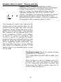
Hawkins Bass Control - Theory and Use
Hawkins Bass Control(parametric)is a unique
subwoofer control circuit included with the Soundstream
Human Reign amplifier. It is capable of removing
subsonic energy in program material while boosting
subwoofer frequencies. The circuit consists of two
controls. One adjusts the frequency of operation and the
other adjusts the range of boost. With both controls
adjusted fully counter-clockwise, no boost is applied and
the amplifier is flat in response down to 20 Hz.
The Boost control adjusts the amount of level
applied at the set frequency.
This is adjustable from flat (0dB) to +9dB. (See
figure 2)
When the Boost is set to 0, Hawkins acts as a
sub-sonic filter only. (See figure 3) The simple
act of removing potentially harmful low
frequencies can improve system output by as
much as 3dB.(see figure 4)
11
The frequency control (Hz) adjusts the
starting point of the subsonic filter. On the
Human reign the high pass filter has two
frequency ranges. When the bass control
switch is set to “SUB SONIC”, the high pass
filter frequency can be adjusted from 13 Hz
up to a maximum of 30Hz. In this setting,
no boost “Q” control is available. This
control is useful for setting the lowest
frequency that your subwoofer will see (see
figure 1). When the bass control switch is
set to “HAWKINS BASS CONTROL”, the
high pass filter frequency can be adjusted
from 30 Hz to a maximum of 70Hz. In this
setting, there is an available boost control
of 0 to +9dB.

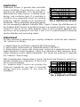
Application
Subwoofer drivers in general have excellent
power handling characteristics over their
operational bandwidth. This bandwidth is
determined by many factors, including driver
design, and enclosure type. It is possible to
overdrive any subwoofer driver by sending
powerful signals outside of its operational
bandwidth. These potentially damaging signals
can be removed by adding a subsonic filter. Figure 5 shows the effectiveness of
the Hawkins Bass Control on woofer excursion in a vented enclosure. The woofer
travels 7.5 mm at 10 Hz. With Hawkins Bass Control properly adjusted, this
excursion can be reduced to less than 1 mm. This is of great benefit to lowering
woofer distortion and increasing output.
Adjustment
An easy method of optimizing your existing subwoofer enclosure with Hawkins’
“Hz” control is as follows:
1. Adjust frequency and boost control to full CCW position.
2. Set the bass control switch to “HAWKINS BASS CONTROL”.
3. While listening to music with strong bass content at a moderate level, slowly
adjust frequency control clockwise. Listen for a reduction of bass response. Now,
rotate frequency control slightly backwards. This serves the purpose of removing
the “subsonic” bass energy.
With Soundstream’s Hawkins Bass Control, the boost and frequency control can
provide virtually any combination of boost and
cut to suit your designs.
So, Hawkins Bass Control can provide the
“tailoring” needed for any type of “assisted”
design and any woofer in any type of
installation.
12
FIG. 5 LIMITED EXCURSION
FIG. 6 VARIOUS SETTINGS

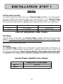
WIRING
POWER AND GROUND
To ensure maximum output from your Human Reign amplifier, use high quality,
low-loss power and ground cables and connections. The Human Reign
amplifiers will accept up to 2 gauge power and ground cables. Determine from
the chart below the minimum gauge power and ground wire for your application.
13
up to 10´
up to 20´
HR 2
HR 4
2 or 4 gauge 2 gauge only
CIRCUIT BREAKERS AND FUSES
EXTERNAL
Like all audio components, the Human Reign amplifier must be fused near the
battery. A fuse or circuit breaker must be located within 18” of the battery. This
will prevent a fire in the event of a shorted cable. See the chart below to
determine the correct fuse value.
INTERNAL
The Human Reign amplifiers are fused with an automotive-type or Maxi-fuse. In
the event of a blown power supply fuse(s), replace with the correct value fuse
found in the chart below. Never replace the fuse with a higher value than what
is supplied. This may result in amplifier damage and will void the warranty!
Human Reign Amplifier Fuse Values
Battery Fuse / Circuit Breaker
200 amp
2 or 4 gauge
2 gauge only
140 amp
HR 2
HR 4

REMOTE TURN-ON
Connect the “Remote” line to the turn-on lead from the source unit. When
+12Volts received, the amplifier will turn on.
SIGNAL CABLE
Use a high quality cable that will be easy to install and has minimal signal loss
to guarantee optimum performance.
SPEAKER CABLE
The Human Reign amplifiers will accept up to 8 gauge speaker cable. Use a
high quality, flexible, multi-strand cable for best performance and longevity.
14

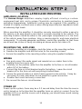
INSTALLATION AND MOUNTING
AMPLIFIER LOCATION
The Human Reign amplifiers employ highly efficient circuitry,a custom-
engineered heat sink, and a unique Chassisink construction to maintain lower
operating temperatures. Additional cooling may be required if the amplifier is
located in a tightly confined area or when driving especially low impedance loads
at extremely high levels.
When mounting the amplifier, it should be securely mounted to either a panel in
the vehicle or an amp board or rack that is securely mounted to the vehicle. The
mounting location should be either in the passenger compartment or in the trunk
of the vehicle, away from moisture, stray or moving objects, and major electrical
components. To provide adequate ventilation, mount the amplifier so that there
are at least two inches of freely circulating air above and to the sides of it.
MOUNTING THE AMPLIFIER
a. Using the amplifier as a template, mark the holes on the mounting surface.
b. Remove the amplifier and drill the holes for the mounting screws.
c. Secure the amplifier to the mounting surface using the supplied hardware.
WIRING
a. Run and connect the audio signal and remote turn-on cables from to the
amplifier form the source unit.
b. Carefully run the positive cable from the amplifier to the fuse or circuit breaker
within 18” of the battery.
c. Connect the fuse or circuit breaker lead to the battery. Leave the circuit
breaker off or the fuse out until everything is bolted down.
d. Secure the ground cable to a solid chassis ground on the vehicle. It may be
necessary to sand paint down to raw metal for a good connection.
e. Double check each and every connection!
f. Re-connect the fuse or circuit breaker.
POWER UP
Power up the system, there may be a 2-3 second delay from the time the source
unit is turned on to the time that the amplifier turns on, which is normal. Once the
amplifier LED is on and the source unit is playing, you should have sound coming
from the speakers.
15

LEVEL SETTING
The input level is adjusted by means of the input level control located on the
control panel of the amplifier. This is a unique dual-stage circuit that adjusts both
level and gain. This topology maintains better S/N Ratio even when using
sources with minimal output.
In the ideal situation, all components in the audio system reach maximum
undistorted output at the same time. If you send a distorted signal to an amplifier,
it is simply going to amplify the distorted input. By setting all components to reach
clipping at the same time, you can maximize the output of your system. For the
Human Reign amplifiers, follow these steps for setting the input levels:
1. Turn the amplifier’s input level to minimum position (counter-clockwise).
2. Set the source unit volume to approximately 3/4 of full volume.
3. While playing dynamic source material, slowly increase the amplifier’s input
level until a near maximum undistorted level is heard in the system.
16

17
TRIDENT PROTECTION CIRCUITRY
Your Human Reign amplifier is protected against both overheating and short
circuits by means of main power fuses and the following circuits:
Speaker Output Protection
Ground Fault Differential
Smart Power Supply Thermal Rollback & Thermal Protection Circuit
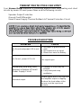
TROUBLESHOOTING
PROBLEM
CAUSE
No Sound and power LED is not
lit
1. No power or ground at the
amp.
2. No remote turn-on signal
3. Blown fuse near the battery
No Sound , power LED is lit
No signal input
Repeatedly blow amp fuse;
frequent activation of Smart
Power Supply Circuit
1. Speaker or leads may be
shorted
2. Verify adequate amp
ventilation.
Distorted output
Output signal level is too high and
the amplifier output is clipping.
Reduce the level either at the
source or at the input level
controls.

SERVICE
Your Soundstream Human Reign amplifier is protected by a limited warranty.
Please read the enclosed warranty card for details. As with all Soundstream
products, a Return Authorization (available from Soundstream) is required for
service of this amplifier.
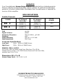
SPECIFICATIONS
Satelite Channels
THD <0.02%
Signal to Noise >90dB
Frequency Response 10Hz to 40kHz
0.5 dB
Damping >500
Input Sensitivity 150 mV t o 5.0 Volts
Input Impedance 10k Ohms
Crossover Specifications
Low Pass: 40Hz - 160Hz at 24dB/Octave
High Pass: 50Hz - 5KHz at 12dB/Octave
Hawkins Bass control
Sub Sonic Filter: No boost, High Pass filter from 13 to 30 Hz.
Hawkins Bass control : 0 to +9 dB Boost; Boost and Sub Sonic filter,
variable from 30 to 70 Hz.
Dimensions (W x D x H)
Human Reign (inch) : 16.3 x 26.1 x 9.2
SOUNDSTREAM TECHNOLOGIES
1550,Maple Avenue., Montebello, CA90640 U.S.A.
Phone 323-722-3333 fax 323-722-1122
www.soundstream.com
POWER
4 Ω Stereo
(8Ω Bridged)
(12.5 Vdc)
2 Ω Stereo
(4Ω Bridged)
(12.5 Vdc)
TOTAL
POWER
125W x 4
(250W x 2)
250W x 4
(500W x 2)
1000
450W x 2
(900W x 1)
800W x 2
(1600W x 1)
1600
HR 2
HR 4
-
 1
1
-
 2
2
-
 3
3
-
 4
4
-
 5
5
-
 6
6
-
 7
7
-
 8
8
-
 9
9
-
 10
10
-
 11
11
-
 12
12
-
 13
13
-
 14
14
-
 15
15
-
 16
16
-
 17
17
-
 18
18


Soundstream HR 2 User manual
- Category
- Musical Equipment
- Type
- User manual
- This manual is also suitable for
Ask a question and I''ll find the answer in the document
Finding information in a document is now easier with AI
Related papers
-
 Soundstream Technologies HRU. 2 User manual
-
Soundstream D’Artagnan5.1 Owner's Manual And Installation Manual
-
-
-
 Soundstream Technologies RUBICON 702 User manual
-
-
 Soundstream Technologies 604 User manual
-
 Soundstream Technologies 501 User manual
-
 Soundstream Technologies 805 User manual
-
 Soundstream Technologies Angina A4 User manual


Other documents
-
 PYLE Audio PLXR5 User manual
-
Lanzar VIBEX2 User manual
-
 MMATS Professional Audio D700.2 User manual
-
 Vienna Acoustics Subson User manual
-
JL Audio CR-1 Owner's manual
-
Rockville RV10.2B Owner's manual
-
 MMATS Professional Audio Speaker D700.4 User manual
-
Pyramid PB-101 User manual
-
Directed Audio XTR2504 User manual
-
AIRPULSE C-9 Owner's Information


