Page is loading ...

March 2011
IMPORTANT
Read this manual carefully before installing, commissioning or
operating this product.
Miller Welding Automation, 281 E. Lies Rd., Carol Stream Il 60188
Telephone: (949) 951-1515 • Fax: (949) 951-9237
Web Site: www.jetline.com • E-mail: [email protected]
OPERATION MANUAL
Model SWC-7 Powered
Carriages & SWC-12 Non-
Powered Carriages

Model SWC-7 Powered & SWC-12 Non-Powered Carriages
- ii -
LIMITED WARRANTY
The sale of products and services by Miller Welding Automation and Miller Welding Automation
Engineering are expressly limited to and made conditional on acceptance of its Terms and Conditions
of Sale, found at https://www.millerwelds.com/automation-terms-of-sale.

Model SWC-7 Powered & SWC-12 Non-Powered Carriages
- iii -
NOTICE
The installation, operation and maintenance guidelines set out in this manual will enable you to
maintain the equipment in peak condition and achieve maximum efficiency with your welding
operation. Please read these instructions carefully to become aware of every advantage.
CAUTION
Only experienced personnel familiar with
the operation and safe practice of welding
equipment should install and/or use
this equipment.

Model SWC-7 Powered & SWC-12 Non-Powered Carriages
- vi -
CONTENTS
Section I .................................................................................................................................................... 1
SAFETY PRECAUTIONS – READ BEFORE USING (som 2013-09) ................................................... 1
1.1 Symbol Usage ..................................................................................................................................... 1
1.2 Arc Welding Hazards ....................................................................................................................... 1
1.3 Additional Symbols for Installation, Operation, And Maintenance .................................................. 4
1.4 California Proposition 65 Warnings ................................................................................................... 6
1.5 Principal Safety Standards ................................................................................................................. 6
1.6 EMF Information ................................................................................................................................ 6
Section II ................................................................................................................................................... 7
Introduction ............................................................................................................................................. 7
Section III .................................................................................................................................................. 8
Specifications ........................................................................................................................................... 8
Section IV ................................................................................................................................................. 9
Installation ............................................................................................................................................... 9
Section V ................................................................................................................................................ 10
Maintenance .......................................................................................................................................... 10
Section VI ............................................................................................................................................... 11
Parts List ................................................................................................................................................. 11

Model SWC-7 Powered & SWC-12 Non-Powered Carriages
- 1 -

- 1 -
SECTION I
SAFETY PRECAUTIONS – READ BEFORE USING
(som 2013-09)
1.1 Symbol Usage
DANGER! − Indicates a hazardous situation which, if not avoided, will result in death or serious injury. The possible hazards are shown in the
adjoining symbols or explained in the text.
Indicates a hazardous situation which, if not avoided, could result in death or serious injury. The possible hazards are shown in the adjoining symbols or
explained in the text.
NOTICE − Indicates statements not related to personal injury.
Indicates special instructions.
This group of symbols means: Warning! Watch Out! ELECTRIC SHOCK, MOVING PARTS, and HOT PARTS hazards.
Consult symbols and related instructions below for necessary actions to avoid the hazards.
1.2 Arc Welding Hazards
The symbols shown below are used throughout this manual to call attention to and identify possible hazards. When you see the symbol,
watch out, and follow the related instructions to avoid the hazard. The safety information given below is only a summary of the more
complete safety information found in the Safety Standards listed in Section 1-5. Read and follow all Safety Standards.
Only qualified persons should install, operate, maintain, and repair this unit.
During operation, keep everybody, especially children, away.
Touching live electrical parts can cause fatal shocks or severe burns. The electrode and work circuit is electrically live whenever the output is
on. The input power circuit and machine internal circuits are also live when power is on. In semiautomatic or automatic wire welding, the wire,
wire reel, drive roll housing, and all metal parts touching the welding wire are electrically live. Incorrectly installed or improperly grounded
equipment is a hazard.
• Do not touch live electrical parts.
• Wear dry, hole-free insulating gloves and body protection.
• Insulate yourself from work and ground using dry insulating mats or covers big enough to prevent any physical contact with the work
or ground.
• Do not use AC output in damp areas, if movement is confined, or if there is a danger of falling.
• Use AC output ONLY if required for the welding process.
• If AC output is required, use remote output control if present on unit.
• Additional safety precautions are required when any of the following electrically hazardous conditions are present: in damp locations
or while wearing wet clothing; on metal structures such as floors, gratings, or scaffolds; when in cramped positions such as sitting,
kneeling, or lying; or when there is a high risk of unavoidable or accidental contact with the work piece or ground. For these
conditions, use the following equipment in order presented: 1) a semiautomatic DC constant voltage (wire) welder, 2) a DC manual
(stick) welder, or 3) an AC welder with reduced open-circuit voltage. In most situations, use of a DC, constant voltage wire welder is
recommended. And, do not work alone!
• Disconnect input power or stop engine before installing or servicing this equipment. Lockout/tagout input power according to OSHA
29 CFR 1910.147 (see Safety Standards).
• Properly install, ground, and operate this equipment according to its Owner’s Manual and national, state, and local codes.
• Always verify the supply ground − check and be sure that input power cord ground wire is properly connected to ground terminal in
disconnect box or that cord plug is connected to a properly grounded receptacle outlet.
• When making input connections, attach proper grounding conductor first − double-check connections.
• Keep cords dry, free of oil and grease, and protected from hot metal and sparks.
• Frequently inspect input power cord and ground conductor for damage or bare wiring – replace immediately if damaged – bare
wiring can kill.
• Turn off all equipment when not in use.
• Do not use worn, damaged, undersized, or repaired cables.
• Do not drape cables over your body.
Protect yourself and others from injury – read, follow and save these important safety precautions and operating instructions.
ELECTRIC SHOCK can kill.

Model SWC-7 Powered & SWC-12 Non-Powered Carriages
- vi -
• If earth grounding of the workpiece is required, ground it directly with a separate cable.
• Do not touch electrode if you are in contact with the work, ground, or another electrode from a different machine.
• Do not touch electrode holders connected to two welding machines at the same time since double open-circuit voltage will be
present.
• Use only well-maintained equipment. Repair or replace damaged parts at once. Maintain unit according to manual.
• Wear a safety harness if working above floor level.
• Keep all panels and covers securely in place.
• Clamp work cable with good metal-to-metal contact to workpiece or worktable as near the weld as practical.
• Insulate work clamp when not connected to workpiece to prevent contact with any metal object.
• Do not connect more than one electrode or work cable to any single weld output terminal. Disconnect cable for process not in use.
• Use GFCI protection when operating auxiliary equipment in damp or wet locations.
SIGNIFICANT DC VOLTAGE exists in inverter welding power sources AFTER removal of input power.
• Turn Off inverter, disconnect input power, and discharge input capacitors according to instructions in Maintenance Section before
touching any parts.
• Do not touch hot parts bare handed.
• Allow cooling period before working on equipment.
• To handle hot parts, use proper tools and/or wear heavy, insulated welding gloves and clothing to prevent burns.
Welding produces fumes and gases. Breathing these fumes and gases can be hazardous to your health.
• Keep your head out of the fumes. Do not breathe the fumes.
• If inside, ventilate the area and/or use local forced ventilation at the arc to remove welding fumes and gases. The recommended way
to determine adequate ventilation is to sample for the composition and quantity of fumes and gases to which personnel are
exposed.
• If ventilation is poor, wear an approved air-supplied respirator.
• Read and understand the Safety Data Sheets (SDSs) and the manufacturer’s instructions for adhesives, coatings, cleaners,
consumables, coolants, degreasers, fluxes, and metals.
• Work in a confined space only if it is well ventilated, or while wearing an air-supplied respirator. Always have a trained watch-person
nearby. Welding fumes and gases can displace air and lower the oxygen level causing injury or death. Be sure the breathing air is
safe.
• Do not weld in locations near degreasing, cleaning, or spraying operations. The heat and rays of the arc can react with vapors to
form highly toxic and irritating gases.
• Do not weld on coated metals, such as galvanized, lead, or cadmium plated steel, unless the coating is removed from the weld area,
the area is well ventilated, and while wearing an air-supplied respirator. The coatings and any metals containing these elements can
give off toxic fumes if welded.
Arc rays from the welding process produce intense visible and invisible (ultraviolet and infrared) rays that can burn eyes and skin. Sparks fly off
from the weld.
• Wear an approved welding helmet fitted with a proper shade of filter lenses to protect your face and eyes from arc rays and sparks
when welding or watching (see ANSI Z49.1 and Z87.1 listed in Safety Standards).
• Wear approved safety glasses with side shields under your helmet.
• Use protective screens or barriers to protect others from flash,glare and sparks; warn others not to watch the arc.
• Wear body protection made from durable, flame−resistant material (leather, heavy cotton, wool). Body protection includes oil-free
clothing such as leather gloves, heavy shirt, cuffless trousers, high shoes, and a cap.
HOT PARTS can burn.
ARC RAYS can burn eyes and skin.
FUMES AND GASES can be hazardous.
- 1 -
Welding on closed containers, such as tanks, drums, or pipes, can cause them to blow up. Sparks can fly off from the welding arc. The flying
sparks, hot workpiece, and hot equipment can cause fires and burns. Accidental contact of electrode to metal objects can cause sparks,
explosion, overheating, or fire. Check and be sure the area is safe before doing any welding.
• Remove all flammables within 35 ft (10.7 m) of the welding arc. If this is not possible, tightly cover them with approved covers.
• Do not weld where flying sparks can strike flammable material.
• Protect yourself and others from flying sparks and hot metal.
• Be alert that welding sparks and hot materials from welding can easily go through small cracks and openings to adjacent areas.
• Watch for fire, and keep a fire extinguisher nearby.
• Be aware that welding on a ceiling, floor, bulkhead, or partition can cause fire on the hidden side.
• Do not weld on containers that have held combustibles, or on closed containers such as tanks, drums, or pipes unless they are
properly prepared according to AWS F4.1 and AWS A6.0 (see Safety Standards).
• Do not weld where the atmosphere may contain flammable dust, gas, or liquid vapors (such as gasoline).
• Connect work cable to the work as close to the welding area as practical to prevent welding current from traveling long, possibly
unknown paths and causing electric shock, sparks, and fire hazards.
• Do not use welder to thaw frozen pipes.
• Remove stick electrode from holder or cut off welding wire at contact tip when not in use.
• Wear body protection made from durable, flame−resistant material (leather, heavy cotton, wool). Body protection includes oil-free
clothing such as leather gloves, heavy shirt, cuffless trousers, high shoes, and a cap.
• Remove any combustibles, such as a butane lighter or matches, from your person before doing any welding.
• After completion of work, inspect area to ensure it is free of sparks, glowing embers, and flames.
• Use only correct fuses or circuit breakers. Do not oversize or bypass them.
• Follow requirements in OSHA 1910.252 (a) (2) (iv) and NFPA 51B for hot work and have a fire watcher and extinguisher nearby.
Read and understand the Safety Data Sheets (SDSs) and the manufacturer’s instructions for adhesives, coatings, cleaners, consumables,
coolants, degreasers, fluxes, and metals.
• Welding, chipping, wire brushing, and grinding cause sparks and flying metal. As welds cool, they can throw off slag.
• Wear approved safety glasses with side shields even under your welding helmet.
• Shut off compressed gas supply when not in use.
• Always ventilate confined spaces or use approved air-supplied respirator.
• Wearers of Pacemakers and other Implanted Medical Devices should keep away.
• Implanted Medical Device wearers should consult their doctor and the device manufacturer before going near arc welding, spot
welding, gouging, plasma arc cutting, or induction heating operations.
• Noise from some processes or equipment can damage hearing.
• Wear approved ear protection if noise level is high.
WELDING can cause fire or explosion.
FLYING METAL or DIRT can injure eyes.
BUILDUP OF GAS can injure or kill.
ELECTRIC AND MAGNETIC FIELDS (EMF) can affect Implanted Medical Devices.
NOISE can damage hearing.
Model SWC-7 Powered & SWC-12 Non-Powered Carriages
- vi -
Compressed gas cylinders contain gas under high pressure. If damaged, a cylinder can explode. Since gas cylinders are normally part of the
welding process, be sure to treat them carefully.
• Protect compressed gas cylinders from excessive heat, mechanical shocks, physical damage, slag, open flames, sparks, and arcs.
• Install cylinders in an upright position by securing to a stationary support or cylinder rack to prevent falling or tipping.
• Keep cylinders away from any welding or other electrical circuits.
• Never drape a welding torch over a gas cylinder.
• Never allow a welding electrode to touch any cylinder.
• Never weld on a pressurized cylinder − explosion will result.
• Use only correct compressed gas cylinders, regulators, hoses, and fittings designed for the specific application; maintain them and
associated parts in good condition.
• Turn face away from valve outlet when opening cylinder valve. Do not stand in front of or behind the regulator when opening the
valve.
• Keep protective cap in place over valve except when cylinder is in use or connected for use.
• Use the right equipment, correct procedures, and sufficient number of persons to lift and move cylinders.
• Read and follow instructions on compressed gas cylinders, associated equipment, and Compressed Gas Association (CGA) publication
P-1 listed in Safety Standards.
1.3 Additional Symbols for Installation, Operation, And Maintenance
• Do not install or place unit on, over, or near combustible surfaces.
• Do not install unit near flammables.
• Do not overload building wiring − be sure power supply system is properly sized, rated, and protected to handle this unit.
• Use lifting eye to lift unit only, NOT running gear, gas cylinders, or any other accessories.
• Use equipment of adequate capacity to lift and support unit.
• If using lift forks to move unit, be sure forks are long enough to extend beyond opposite side of unit.
• Keep equipment (cables and cords) away from moving vehicles when working from an aerial location.
• Follow the guidelines in the Applications Manual for the Revised NIOSH Lifting Equation (Publication No. 94−110) when manually
lifting heavy parts or equipment.
• Allow cooling period; follow rated duty cycle.
• Reduce current or reduce duty cycle before starting to weld again.
• Do not block or filter airflow to unit.
• Wear a face shield to protect eyes and face.
• Shape tungsten electrode only on grinder with proper guards in a safe location wearing proper face, hand, and body protection.
• Sparks can cause fires — keep flammables away.
• Put on grounded wrist strap BEFORE handling boards or parts.
• Use proper static-proof bags and boxes to store, move, or ship PC boards.
CYLINDERS can explode if damaged.
FIRE OR EXPLOSION hazard.
FALLING EQUIPMENT can injure.
OVERUSE can cause OVERHEATING
FLYING SPARKS can injure.
STATIC (ESD) can damage PC boards.
MOVING PARTS can injure.
- 1 -
• Keep away from moving parts.
• Keep away from pinch points such as drive rolls.
• Do not press gun trigger until instructed to do so.
• Do not point gun toward any part of the body, other people, or any metal when threading welding wire.
• Do not use welder to charge batteries or jump start vehicles unless it has a battery charging feature designed for this purpose.
• Keep away from moving parts such as fans.
• Keep all doors, panels, covers, and guards closed and securely in place.
• Have only qualified persons remove doors, panels, covers, or guards for maintenance and troubleshooting as necessary.
• Reinstall doors, panels, covers, or guards when maintenance is finished and before reconnecting input power.
• Read and follow all labels and the Owner’s Manual carefully before installing, operating, or servicing unit. Read the safety
information at the beginning of the manual and in each section.
• Use only genuine replacement parts from the manufacturer.
• Perform maintenance and service according to the Owner’s Manuals, industry standards, and national, state, and local codes.
• High-frequency (H.F.) can interfere with radio navigation, safety services, computers, and communications equipment.
• Have only qualified persons familiar with electronic equipment perform this installation.
• The user is responsible for having a qualified electrician promptly correct any interference problem resulting from the installation.
• If notified by the FCC about interference, stop using the equipment at once.
• Have the installation regularly checked and maintained.
• Keep high-frequency source doors and panels tightly shut, keep spark gaps at correct setting, and use grounding and shielding to
minimize the possibility of interference.
• Electromagnetic energy can interfere with sensitive electronic equipment such as computers and computer-driven equipment such
as robots.
• Be sure all equipment in the welding area is electromagnetically compatible.
• To reduce possible interference, keep weld cables as short as possible, close together, and down low, such as on the floor.
• Locate welding operation 100 meters from any sensitive electronic equipment.
• Be sure this welding machine is installed and grounded according to this manual.
• If interference still occurs, the user must take extra measures such as moving the welding machine, using shielded cables, using line
filters, or shielding the work area.
WELDING WIRE can injure.
BATTERY EXPLOSION can injure.
MOVING PARTS can injure.
READ INSTRUCTIONS.
H.F. RADIATION can cause interference.
ARC WELDING can cause interference.

Model SWC-7 Powered & SWC-12 Non-Powered Carriages
- vi -
1.4 California Proposition 65 Warnings
Welding or cutting equipment produces fumes or gases which contain chemicals known to the State of California to cause birth defects
and, in some cases, cancer. (California Health & Safety Code Section 25249.5 et seq.)
This product contains chemicals, including lead, known to the state of California to cause cancer, birth defects, or other reproductive
harm. Wash hands after use.
1.5 Principal Safety Standards
Safety in Welding, Cutting, and Allied Processes, ANSI Standard Z49.1, is available as a free download from the American Welding Society at
http://www.aws.org or purchased from Global Engineering Documents (phone: 1-877-413-5184, website: www.global.ihs.com
).
Safe Practices for the Preparation of Containers and Piping for Welding and Cutting, American Welding Society Standard AWS F4.1, from Global
Engineering Documents (phone: 1-877-413-5184, website: www.global.ihs.com
).
Safe Practices for Welding and Cutting Containers that have Held Combustibles, American Welding Society Standard AWS A6.0, from Global
EngineeringDocuments (phone: 1-877-413-5184, website: www.global.ihs.com
).
National Electrical Code, NFPA Standard 70, from National Fire Protection Association, Quincy, MA 02269 (phone: 1-800-344-3555, website:
www.nfpa.org and www. sparky.org).
Safe Handling of Compressed Gases in Cylinders, CGA Pamphlet P-1, from Compressed Gas Association, 14501 George Carter Way, Suite 103,
Chantilly, VA 20151 (phone: 703-788-2700, website:www.cganet.com).
Safety in Welding, Cutting, and Allied Processes, CSA Standard W117.2, from Canadian Standards Association, Standards Sales, 5060 Spectrum Way,
Suite 100, Ontario, Canada L4W 5NS (phone: 800-463-6727, website: www.csa-international.org
).
Safe Practice For Occupational And Educational Eye And Face Protection, ANSI Standard Z87.1, from American National Standards Institute, 25 West
43rd Street, New York, NY 10036 (phone: 212-642-4900, web-site: www.ansi.org
).
Standard for Fire Prevention During Welding, Cutting, and Other Hot Work, NFPA Standard 51B, from National Fire Protection Association, Quincy,
MA 02269 (phone: 1-800-344-3555, website: www.nfpa.org
.
OSHA, Occupational Safety and Health Standards for General Industry, Title 29, Code of Federal Regulations (CFR), Part 1910, Subpart Q, and Part
1926, Subpart J, from U.S. Government Printing Office, Superintendent of Documents, P.O. Box 371954, Pittsburgh, PA 15250-7954 (phone: 1-866-
512-1800) (there are 10 OSHA Regional Offices— phone for Region 5, Chicago, is 312-353-2220, website: www.osha.gov
).
Applications Manual for the Revised NIOSH Lifting Equation, The National Institute for Occupational Safety and Health (NIOSH), 1600 Clifton Rd,
Atlanta, GA 30333 (phone: 1-800-232-4636, website: www.cdc.gov/NIOSH
).
1.6 EMF Information
Electric current flowing through any conductor causes localized electric and magnetic fields (EMF). The current from arc welding (and allied processes
including spot welding, gouging, plasma arc cutting, and induction heating operations) creates an EMF field around the welding circuit. EMF fields
may interfere with some medical implants, e.g. pacemakers. Protective measures for persons wearing medical implants have to be taken. For
example, restrict access for passers−by or conduct individual risk assessment for welders. All welders should use the following procedures in order to
minimize exposure to EMF fields from the welding circuit:
1. Keep cables close together by twisting or taping them, or using a cable cover.
2. Do not place your body between welding cables. Arrange cables to one side and away from the operator.
3. Do not coil or drape cables around your body.
4. Keep head and trunk as far away from the equipment in the welding circuit as possible.
5. Connect work clamp to workpiece as close to the weld as possible.
6. Do not work next to, sit or lean on the welding power source.
7. Do not weld whilst carrying the welding power source or wire feeder.
About Implanted Medical Devices:
Implanted Medical Device wearers should consult their doctor and the device manufacturer before performing or going near arc welding, spot
welding, gouging, plasma arc cutting, or induction heating operations. If cleared by your doctor, then following the above procedures is recom-
mended.

- 7 -
SECTION II
INTRODUCTION
The SWC-7 and SWC-12 V-way travel carriages
provide a heavy duty vertical mounting
platform 27” wide and 17” high (685 x 432
mm) for mounting all popular types of semi-
automatic and automatic welding processes. It
is designed for use with TKHV V-way tracks.
The platform itself is made from heavy alumi-
num plate and travels on fourteen guide
wheels. Nine of these are at the top of the
carriage and carry the weight and side thrust
due to the offset weight of the welding
equipment. Five guide wheels are mounted at
the bottom, holding the carriage in alignment
and also taking a front load.
The carriage is driven through a gear reducer
and pinion gear by a D.C. permanent magnet,
revers- ible 1/4 HP motor. The pinion engages
the rack mounted on the front of the V-way
track.
The SWC-12 non-powered carriage is identical
to the SWC-7 powered carriage except that
the control and motor have been removed. A
manual locking knob and shoe will secure the
carriage at a position on the track chosen by
the operator.

Model SWC-7 Powered & SWC-12 Non-Powered Carriages
- 8 -
SECTION III
SPECIFICATIONS
Weight capacity of the carriage is 1,000 lb (450
kg) at 12” (304 mm) from the carriage face.
A. Control
The SWC-7 carriage is supplied with the
9700T microprocessor control as standard.
The travel of the standard carriage is
governed from the control box which is
typically mounted on the face of the carriage.
The control has been designed as a front
mounting unit to allow easy relocation or
removal. The wiring is complete and it is
ready for operation.
For information on the carriage control
supplied with your carriage, refer to the
supplied control manual.
A. Speed Ranges
Speed holding accuracy is ±1% of the rated
speed. The speed ranges available with the
SWC-7 style carriages are:
SWC-7A 4 to 165 IPM
100 to 4200 mm/min
SWC-7B 3 to 108 IPM
75 to 2750 mm/min
SWC-7C 2 to 67 IPM
50 to 1700 mm/min
SWC-7D 1 to 45 IPM
25 to 1150 mm/min

- 9 -
SECTION IV
INSTALLATION
In most cases, carriage assemblies (either with
or without welding equipment) are removed
from the track for shipping. To install the
carriage on the track, use the following
procedure.
Remove the carriage safety stop from the side
of the track. Slide the carriage onto the track
until the pinion gear just touches the gear
rack. For SWC-7 models, attach power to the
carriage control and use the control to power
the carriage onto the gear rack. The upper
guide wheels have been adjusted before
shipment to allow the carriage to travel with
a minimum of play.
If it should become necessary to readjust the
carriage, loosen the hex nut and hex head
screw. With the carriage unloaded and the
front guide wheels pressed against the V-way
rail, adjust the rear guide wheels with the
adjustable adaptor bushing. Correct
adjustment has been achieved when the rear
guide wheels can be tightly turned by hand.
After adjustment, hold the adjustable adaptor
bushing, tighten the hex head screw and the
hex nut.
The hose support bracket has been removed
from the carriage for shipment and is
mounted to the shipping pallet with lag
screws. The bracket can be re-attached to the
top of the carriage where the mounting plate
is located.

Model SWC-7 Powered & SWC-12 Non-Powered Carriages
- 10 -
SECTION V
MAINTENANCE
The Miller Welding Automation standard
travel carriage has been designed to give
trouble free operation under normal working
conditions and requires little maintenance.
The following items should be checked
periodically for optimum perfor- mance.
1. Motor brushes: replace if worn.
2. Periodically change the gear oil in the
speed reducer. Use SAE 90W gear type oil.
3. Keep operator personnel informed of
maintenance requirements and remind
them that this is a precision piece of
equipment which can be damaged by
abuse.

- 11 -
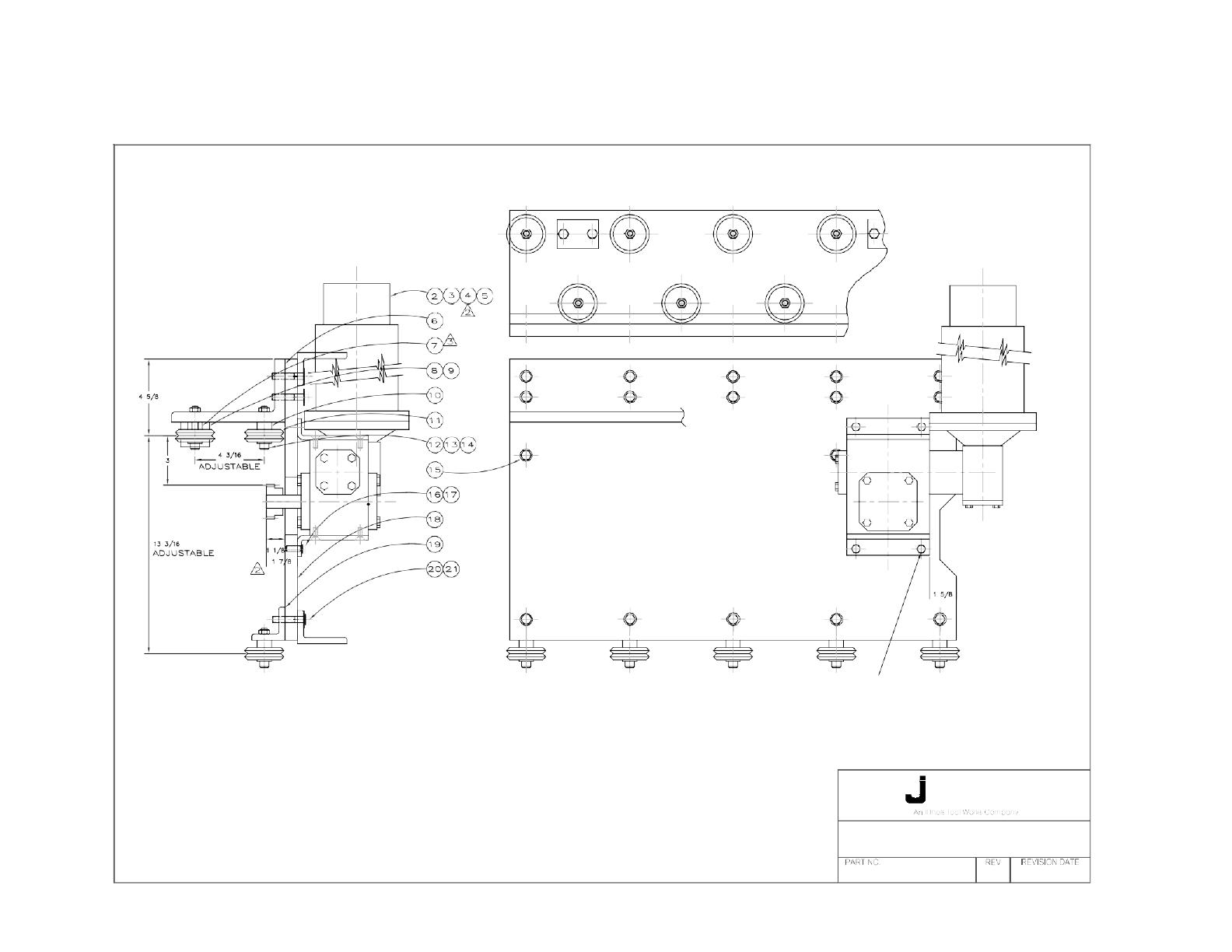
SECTION VI
PARTS LIST
The following pages provide a detailed parts
list of all the elements of the travel carriage.
They are arranged so that the parts list on the
right hand page corresponds with the
assembly illustrated on the left hand page.
Item numbers shown in the parts list refer to
those numbers contained in the balloons in
the drawing. On each parts list, the quantities
shown are the number of items used in that
particular assem- bly.
Two columns are included in the list to show
the spare parts which are recommended to
be stocked by the user. The two levels can be
de- fined as follows:
Level 1 These are the spares recommended
for US domestic users whose use of
the product does not exceed 2000
hours per year.
Level 2 These are the spares recommended
for international use of the product
or for US domestic users who will
use the products in excess of 2000
hours per year.
The following parts lists are included in this
manual. Their appropriate page numbers are
listed.
SWC-7 Carriage..................................... 14/15
etline
EXTRA HEAVY SUPERDUTY CARRIAGE
FOR CANTILEVERED LOADS
SWC-7 F
Model SWC-7 Powered & SWC-12 Non-Powered Carriages
- 14 -

Model SWC-7 Powered & SWC-12 Non-Powered Carriages
- 15 -
SWC-7 EXTRA HEAVY, SUPERDUTY CARRIAGE - POWERED FOR
CANTILEVERED LOADS
Recommended
Item
Part
Level
Level
No.
No.
Description
Qty
I
II
2 *9700T Control Box Assembly ..............................................1
3 Motor........................................................................1 1 1
4 Worm Gear Reducer .................................................1
5 Gear ..........................................................................1
6 SWC-7-110 Upper Truck Detail ...................................................1
7 BX4 Adjustable Adapter bushing, dual-vee .....................5
8 SWC-7-SB2 Safety Block Detail ...................................................2
9 3/8-16x1 1/4 Hex Head Screw .......................................................4
10 B-4 Stationary Adapter Bushing, dual-vee .....................9
11 W-4 Guide Wheel, dual-vee ...........................................14
12 3/8-16x2 1/4 Hex Head Screw .......................................................9
13 3/8 Lock Washer ................................................................ 14
14 3/8-16 Hex Nut ..................................................................14
15 3/8-16x1 1/2 Hex Head Screw .......................................................2
16 5/16-18x1 Hex Head Screw .......................................................4
17 5/16 Lock Washer .................................................................. 4
18 SWC-7-100 Frame Detail .............................................................1
19 SWC-7-120 Lower Truck Detail ...................................................1
20 3/8-16x2 Hex Head Screw .....................................................20
21 3/8 Flat Washer .................................................................. 17
*Note: Other controls are available and may have been supplied with the carriage. See manual pro-
vided with control for parts breakdown.
/