
POWER TOOLS
TECHNICAL DATA
AND
SERVICE MANUAL
CHARGER
UC 9SD
SPECIFICATIONS AND PARTS ARE SUBJECT TO CHANGE FOR IMPROVEMENT
LIST No. F836 Nov. 1999
U
MODEL
UC 9SD

Page
CONTENTS
[ Business Section ]
1. PRODUCT NAME
••••••••••••••••••••••••••••••••••••••••••••••••••••••••••••••••••••••••••••••••••••••••••••••••••••••••••••••••••••••••
1
2. MARKETING OBJECTIVE
••••••••••••••••••••••••••••••••••••••••••••••••••••••••••••••••••••••••••••••••••••••••••••••••••••••••••
1
3. APPLICATIONS
••••••••••••••••••••••••••••••••••••••••••••••••••••••••••••••••••••••••••••••••••••••••••••••••••••••••••••••••••••••••••
1
4. SELLING POINTS
•••••••••••••••••••••••••••••••••••••••••••••••••••••••••••••••••••••••••••••••••••••••••••••••••••••••••••••••••••••••
1
5. SPECIFICATIONS
•••••••••••••••••••••••••••••••••••••••••••••••••••••••••••••••••••••••••••••••••••••••••••••••••••••••••••••••••••••••
2
5-1. Specifications
••••••••••••••••••••••••••••••••••••••••••••••••••••••••••••••••••••••••••••••••••••••••••••••••••••••••••••••••••••••••
2
5-2. Comparisons with Similar Product
•••••••••••••••••••••••••••••••••••••••••••••••••••••••••••••••••••••••••••••••••••••••••••
2
6. PRECAUTIONS IN SALES PROMOTION
•••••••••••••••••••••••••••••••••••••••••••••••••••••••••••••••••••••••••••••••••••
3
6-1. Safety Instructions
•••••••••••••••••••••••••••••••••••••••••••••••••••••••••••••••••••••••••••••••••••••••••••••••••••••••••••••••••
3
6-2. Points Requiring Special Attention During Sales Promotion
••••••••••••••••••••••••••••••••••••••••••••••••••••••
4
[ Service Section ]
7. REFERENCE MATERIAL
•••••••••••••••••••••••••••••••••••••••••••••••••••••••••••••••••••••••••••••••••••••••••••••••••••••••••••
5
7-1. Model UC 9SD Structure
••••••••••••••••••••••••••••••••••••••••••••••••••••••••••••••••••••••••••••••••••••••••••••••••••••••••
5
8. PRECAUTIONS IN DISASSEMBLY AND REASSEMBLY
•••••••••••••••••••••••••••••••••••••••••••••••••••••••••••
5
8-1. Disassembly
••••••••••••••••••••••••••••••••••••••••••••••••••••••••••••••••••••••••••••••••••••••••••••••••••••••••••••••••••••••••••
5
8-2. Reassembly
••••••••••••••••••••••••••••••••••••••••••••••••••••••••••••••••••••••••••••••••••••••••••••••••••••••••••••••••••••••••••
6
8-3. Confirmation after Reassembly
••••••••••••••••••••••••••••••••••••••••••••••••••••••••••••••••••••••••••••••••••••••••••••••
6
9. TROUBLESHOOTING GUIDE
••••••••••••••••••••••••••••••••••••••••••••••••••••••••••••••••••••••••••••••••••••••••••••••••••••
7
9-1. Failure During Charging
••••••••••••••••••••••••••••••••••••••••••••••••••••••••••••••••••••••••••••••••••••••••••••••••••••••••
7
10. STANDARD REPAIR TIME (UNIT) SCHEDULES
•••••••••••••••••••••••••••••••••••••••••••••••••••••••••••••••••••••
11
[ Appendix ]
Assembly Diagram for UC 9SD
•••••••••••••••••••••••••••••••••••••••••••••••••••••••••••••••••••••••••••••••••••••••••••••••••••••
12
Notice for use
Specifications and parts are subject to change for improvement.
Refer to Hitachi Power Tool Technical News for further information.

--- 1 ---
1. PRODUCT NAME
Hitachi Charger, Model UC 9SD
2. MARKETING OBJECTIVE
The Model UC 9SD is an inexpensive 9.6 V-only charger that has been developed to promote sales of our low-
cost cordless tools. It is designed to charge the Hitachi types EB 9S, FEB 9 and FEB 9S rechargeable batteries.
3. APPLICATIONS
Charging of Hitachi 9.6 V Rechargeable Batteries
Applicable Batteries EB 9S [9.6 V 1300 mAh (4-terminal)]
FEB 9 [9.6 V 1300 mAh (3-terminal)]
FEB 9S [9.6 V 1400 mAh (4-terminal)]
4. SELLING POINTS
Thermostat protects
overcharging.
Red pilot lamp shows easy
confirmation of charging state.
EB 9S
FEB 9
FEB 9S

--- 2 ---
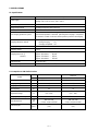
5. SPECIFICATIONS
5-1. Specifications
Descriptions
Item
Frequency: 50 Hz, 60 Hz
Voltage: 110 V, 120 V, 220 V, 230 V, 240 V
30 W
Isolating transformer with center tap
Full wave rectification
A thermostat monitors the storage battery surface temperature. When a
specified temperature is detected, indicating that charging is completed,
an electronic control circuit turns off the power to prevent overcharging.
Pilot lamp indication:
During charging: On
Charging completed: Off
9.6 V
1.55 A
Approx. 55 minutes
••••••
EB 9S
Approx. 85 minutes
••••••
EB 9B
Approx. 55 minutes
••••••
FEB 9
Approx. 60 minutes
••••••
FEB 9S
1.2 kg (2.6 lbs.)
10 ˚C --- 40 ˚C (50 ˚F --- 104 ˚F)
Power supply
Input capacity
Voltage drop method
Rectifying method
Overcharging protection system
Charging indication method
Charging voltage
Charging current
Charging time at 20 ˚C
(at 68 ˚F)
Product weight
Operating temperature
5-2. Comparisons with Similar Product
Model
Applicable ambient
temperature range
HITACHI
UC 9SD
Charging time
Charging current
Outer dimensions
Product weight
HITACHI
Charging voltage
Input capacity
Charging completion system
Unit
min.
V
A
W
˚C
(˚F)
mm
(in)
kg
(Ibs.)
60 (FEB 9S storage batteries)
9.6
1.55
30
10 --- 40
(50 --- 104)
Thermostat
181 x 87 x 80
(7-1/8 x 3-7/16 x 3-5/32)
1.2
(2.6)
UC 12SD
60 (FEB 12S storage batteries)
12
1.55
51
10 --- 40
(50 --- 104)
Thermostat
181 x 87 x 80
(7-1/8 x 3-7/16 x 3-5/32)
1.5
(3.3)

--- 3 ---
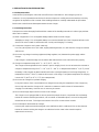
6. PRECAUTIONS IN SALES PROMOTION
6-1. Safety Instructions
In the interest of promoting the safest and most efficient use of the Model UC 9SD Charger by all of our
customers, it is very important that at the time of sale the salesperson carefully ensures that the buyer seriously
recognizes the importance of the contents of the Handling Instructions, and fully understands the precautions
listed on the Caution Plate and Nameplate attached to the Charger.
6-1-1. Handling Instructions
Salespersons must be thoroughly familiar with the contents of the Handling Instructions in order to give pertinent
advice to the customer.
(1) Never charge Hitachi 7.2 V rechargeable battery with the Model UC 9SD Charger:
Attempting to charge 7.2 V rechargeable battery can cause the thermal fuse of the Charger transformer or the
electric fuse on the Printed Circuit Board to blow. Strictly avoid charging 7.2 V battery.
(2) Connect the Charger to an AC power outlet only:
Use of any other power source (DC outlet, engine-powered generator, etc.) will cause the Charger to overheat
and burn out.
(3) Do not use any voltage increasing equipment (voltage regulator, etc.) between the power supply and the
Charger:
If the Charger is used with voltage over and above that indicated on the unit, it will not function properly.
(4) Charge at a temperature range of 10 ˚C --- 40 ˚C (50 ˚F --- 104 ˚F):
The Charger and storage batteries each contain a special charging circuit. Be sure to instruct the customer to
charge at a temperature range of 10 ˚C --- 40 ˚C (50 ˚F --- 104 ˚F). In temperatures below 10 ˚C (50 ˚F), even if
the battery is fully charged, the thermostat will not function causing the battery to overcharge dangerously. In
temperatures over 40 ˚C (104 ˚F), batteries will not reach a full charge. The optimum temperature for charging
is around 20 ˚C (68 ˚F) to 25 ˚C (77 ˚F) (room temperature).
(5) Do not use the Charger for repeated charging:
In very hot locations, if two or more batteries are charged successively, the temperature of the Charger may
rise too high and cause the Charger to fail. Instruct the customer to wait for at least 15 minutes before
charging a second battery. Particular care is necessary in summer.
(6) Do not insert foreign objects into the air vents on the Charger:
The Charger case is equipped with air vents to protect the internal electronic components from overheating.
Instruct the customer that foreign materials, such as metallic or flammable objects, are not to be dropped or
inserted into the air vents. This might cause electrical shock, fire or other serious hazards.
(7) Do not attempt to disassemble the Charger:
Incorrect parts replacement and/or wiring will cause malfunctions which could result in fire or other hazards.
Instruct the customer to bring the charger to an authorized service center in the event that repair or
replacement is necessary.

--- 4 ---
6-2. Points Requiring Special Attention During Sales Promotion
The customer should be advised of the following points during sales promotion of the Charger.
6-2-1. Charging May Not Be Possible When the Storage Battery Temperature Is High
Charging may not be possible if the temperature of the battery is 40 ˚C (104 ˚F) or higher after it has been
exposed to direct sunlight for a long time or immediately after it has been used. In such cases, the customer
should be advised to place the battery in the shade with good airflow, and allow it to cool sufficiently prior to
recharging. This condition is common to all existing chargers (both Hitachi's and competitor's models) which
employ temperature sensitive devices to terminate charging. The cooling period required before charging varies
from a few minutes to about 30 minutes, depending on the length of time the battery was used and the ambient
temperature.
6-2-2. If the Ambient Temperature or Power Supply
Voltage Is Low, Charging Time May Be Longer
The charging time for UC 9SD is greatly influenced by
the ambient temperature and input power supply
voltage.
The relationship between input power supply voltage
and charging time is shown in Fig. 1.
If the input power supply voltage is high, charging
takes less time; if low, it takes more time. Be sure to
advise the customer to charge the batteries at the
ambient temperature specified in the Handling
Instructions and at the rated voltage listed on the
nameplate.
100
90
80
70
60
50
40
30
20
10
0
(minutes)
Charging time
Ambient temperature
10 C (50 F)
20 C (68 F)
Storage battery: FEB 9S
95 % of
rated
voltage
Rated voltage
(Voltage listed
on nameplate)
105 % of
rated
voltage
Input power supply voltage
Fig. 1 Relationship between input power supply
voltage and charging time

--- 5 ---
7. REFERENCE MATERIAL
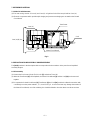
7-1. Model UC 9SD Structure
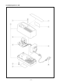
(1) The outer casing consists of Case (A) and Case (B). A light bar for the Pilot Lamp is built into Case (A).
(2) Electronic components which provide rapid charging and prevent overcharging are mounted on the Printed
Circuit Board.
Fig. 2
Case (A)
Case (A).(B) Set
Case (B)
Printed Circuit Board
Transformer
Cord
8. PRECAUTIONS IN DISASSEMBLY AND REASSEMBLY
The [Bold] numbers in the descriptions below correspond to the item numbers in the parts list and exploded
assembly diagram.
8-1. Disassembly
(1) Remove the four Screws (Plastic Tie) D4 x 20 [5], and take off Case (B).
(2) When the Transformer [9] is lifted upward, the Printed Circuit Board [4] and the Cord [10] can be removed
together.
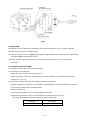
(3) To separate the Printed Circuit Board [4], Transformer [9] and Cord [10], melt their soldered connections with
a soldering iron at the points marked 1, 2, 3, 4 and 5 in Fig. 3. As excessive heat may damage the material of
the Printed Circuit Board, use of the soldering iron should be limited to less than three seconds at one time.

--- 6 ---
Fig. 3
Printed Circuit Board
Lead Wire
(A different colored)
Lead Wire
(The same colors)
Transformer
Cord
8-2. Reassembly
Reassembly can be accomplished by following the disassembly procedures in reverse. However, particular
attention should be given to the following points.
(1) Solder the lead wires of the Cord [10] after passing their stripped end portions through the holes of the Printed
Circuit Board [4] and bending them securely.
(2) Be very careful to ensure that the lead wires are not pinched between Case (A) and Case (B) during
reassembly.
8-3. Confirmation after Reassembly
On completion of reassembly, confirm the following items.
(1) Confirmation of Charging State
Confirm that the Pilot Lamp on the Charger goes on.
Confirm that the Pilot Lamp goes off approximately 60 minutes after the start of charging (when FEB 9S is
charged at 20 ˚C (68 ˚F)).
(2) Measure the Insulation Resistance and Conduct a Dielectric Strength Test
Insulation Resistance: 10 megohms or more between the plug blade of Cord and the Nameplate or fastening
screws on the Case with DC 500 V Megohm Tester.
Dielectric Strength Test:
(a) Between the plug blade of the Cord and charging terminal blade
(b) Between the plug blade of the Cord and Nameplate or fastening screws on the Case
The dielectric strength test should be conducted at the following voltage:
Nameplate Test voltage
110, 120, 220, 230, 240 V AC 1,250 V (1 minute)

--- 7 ---
(CAUTION) Measurement of insulation resistance and the dielectric strength test must be conducted
between the plug blade and the nameplate or fastening screws on the case, and between the
plug blade and the charging terminal blade. Under no circumstances should tests be
conducted between both blades of the plug, or both blades of the charging terminal, which
may cause burnout of the Charger.
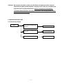
9. TROUBLESHOOTING GUIDE
9-1. Failure During Charging
Failure
Pilot Lamp on, Charger does
not go on.
To Failure Mode (A)
Pilot Lamp on, Charger does
not go off.
To Failure Mode (B)
Abnormal heat is generated.
To Failure Mode (C)

--- 8 ---
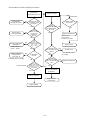
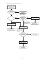
(1) Failure Mode (A) Steps and Repair Procedures
Follow proper
charging procedures.
Remove dirt or
correct abnormality.
Charge at appropriate
temperature.
10 C --- 40 C
(50 F --- 104 F)
Battery cannot be
charged if over
40 C (104 F).
Cool battery before charging.
NO
YES
NO
YES
Check with tester.
Pilot Lamp on,
Charger does not go on.
Is battery charged
according to proper
procedures ?
Are connection
terminals on Charger
or battery dirty,
deformed or
abnormal?
Is the
temperature range
appropriate for charging?
10 C --- 40 C
(50 F --- 104 F)
Is the battery
too hot?
What is the
voltage of the battery
between the (+) and (-)
terminals and (+) and
(T) terminals?
Battery is defective.
Replace battery.
YES
NO
YES
NO
DC 0 V
Defective Charger
Is there
continuity between
the blades of the
AC Plug?
Is the fuse on
the secondary side
blown?
Is there a
disconnected lead
wire on the secondary
side?
Printed Circuit Board
is defective.
Replace Printed
Circuit Board.
YES
NO
YES
YES
YES
NO
NO
NO
Circuit break
Is there a break
in the Cord?
Replace Transformer.
Thermal fuse on
primary side of
Transformer is melted.
Replace Cord.
Replace fuse.
Replace Transformer.
* 7.2 V batteries cannot
be charged.
DC 9.6 V

--- 9 ---
(2) Failure Mode (B) Steps and Repair Procedures
Pilot Lamp on, Charger
does not go off.
Is the
temperature range
appropriate for charging?
10 C --- 40 C
(50 F --- 104 F)
Is the battery warm ?
Battery is defective.
Replace battery.
YES
YES
YES
NO
NO
Is the
thermostat in the
warm battery
open?
Charge at appropriate
temperature.
10 C --- 40 C
(50 F --- 104 F)
Check continuity
between (-) and (T)
terminals of the warm
battery with a tester.
Defective Charger
Disconnect AC Plug
from power supply
and disassemble
Charger.
Are there any
defective wiring
connections?
Replace Printed
Circuit Board.
Printed Circuit
Board is defective.
YES
NO
NO
Battery is defective.
Replace battery.
Correct wiring.

--- 10 ---
(3) Failure Mode (C) Steps and Repair Procedures
Abnormal heat is
generated.
Does the Pilot
Lamp go off
after completion
of charging?
Is the heat
generated by
the battery or
the charger?
Printed Circuit Board
is defective.
Is the heat
generated by the
Transformer?
Charger
Replace Printed
Circuit Board.
Battery
Warming of the battery in the
final stage of charging is normal.
To Failure Mode (B)
Replace battery.
Replace Transformer.
* 7.2 V batteries cannot
be charged.
YES
YES
YES
NO
NO
NO

--- 11 ---
10. STANDARD REPAIR TIME (UNIT) SCHEDULES
MODEL 10 20 30 40
Fixed
Variable
UC 9SD
Work Flow
Light Bar
Fuse (6.3 A)
60 min.
50
Case (A).(B)
Set
Printed Circuit
Board
Transformer
Cord
General Assembly

--- 12 ---
Assembly Diagram for UC 9SD

--- 13 ---
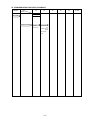
: ALTERNATIVE PARTS
*
UC 9SD
ITEM
NO.
CODE NO. DESCRIPTION
NO.
USED
REMARKS
---
2
---
9
---
99
Printed in Japan
(99910 N)
PARTS
1 318-258 LIGHT BAR 1
* 2 318-267 CASE (A).(B) SET 1
* 2 318-268 CASE (A).(B) SET 1 FOR AUS
3 314-972 FUSE (6.3A/250V) 1
4 318-256 PRINTED CIRCUIT BOARD 1
5 994-806 SCREW (PLASTIC TIE) D4X20 4
6 NAME PLATE 1
7 HITACHI LABEL 1
8 CAUTION LABEL 1
* 9 318-270 TRANSFORMER 120V 1
* 9 318-271 TRANSFORMER 220V 1
* 9 318-272 TRANSFORMER 230V 1
* 9 318-273 TRANSFORMER 240V 1
* 10 318-262 CORD 1
* 10 318-259 CORD 1 FOR USA,CAN
* 10 318-260 CORD 1 FOR NZL,AUS
* 10 318-261 CORD 1 FOR GBR,KUW
-
 1
1
-
 2
2
-
 3
3
-
 4
4
-
 5
5
-
 6
6
-
 7
7
-
 8
8
-
 9
9
-
 10
10
-
 11
11
-
 12
12
-
 13
13
-
 14
14
-
 15
15


Hitachi SV 12SD Technical Data And Service Manual
- Type
- Technical Data And Service Manual
- This manual is also suitable for
Ask a question and I''ll find the answer in the document
Finding information in a document is now easier with AI
Related papers
-
Hitachi FDS 12DVA Technical And Service Manual
-
-
-
-
Hitachi DS 12DVF3 Technical Data And Service Manual
-
-
-
-
-