Page is loading ...

INSTALLATION &
OPERATION MANUAL
BCD301 SERIES
BCD601 SERIES
Battery Equalizer
8128 River Way, Delta B.C. V4G 1K5 Canada T. 604.946.9981 F. 604.946.9983 TF. 800.668.3884 (US/CANADA)
www.analyticsystems.com
An ISO9001 and AS9100 Registered Company Battery Chargers • Inverters • Power Supplies • Voltage Converters

Copyright (2005-2016) Analytic Systems Ware (1993) Ltd.
Revised - May 19, 2016

3
IMPORTANT & SAFETY INSTRUCTIONS
SAVE THESE INSTRUCTIONS — This manual contains important safety and operating
instructions for the battery charger.
ALL BATTERY CHARGERS
1. CAUTION — To reduce risk of injury, charge only lead acid or sealed gel cell type
rechargeable batteries. Other types of batteries may burst causing personal injury and
damage.
2. Do not expose battery charger to rain or snow.
3. Use of an attachment not recommended or sold by the battery charger manufacturer may
result in a risk of re, electric shock, or injury to persons.
4. Do not disassemble battery charger; take it to a qualied serviceman when service or
repair is required. Incorrect reassembly may result in a risk of electric shock or re.
5. To reduce risk of electric shock, disconnect battery charger from batteries or other DC
supply before attempting any maintenance or cleaning. Turning off controls will not
reduce this risk.
GENERAL WARNING
1. WARNING — RISK OF EXPLOSIVE GASES.
i. i) WORKING IN VICINITY OF A LEAD-ACID BATTERY IS DANGEROUS. BATTERIES
GENERATE EXPLOSIVE GASES DURING NORMAL BATTERY OPERATION. FOR THIS
REASON, IT IS OF UTMOST IMPORTANCE THAT EACH TIME BEFORE SERVICING
EQUIPMENT IN THE VICINITY OF THE BATTERY, YOU READ THIS MANUAL AND
FOLLOW THE INSTRUCTIONS EXACTLY.
ii. ii) To reduce risk of battery explosion, follow these instructions and those published
by battery manufacturer and manufacturer of any equipment you intend to use in
vicinity of battery. Review cautionary marking on these products and on engine.
2. PERSONAL PRECAUTIONS
i. Someone should be within range of your voice or close enough to come to your aid
when you work near a lead-acid battery.
ii. Have plenty of fresh water and soap nearby in case battery acid contacts skin,
clothing, or eyes.
iii. Wear complete eye protection and clothing protection. Avoid touching eyes while
working near battery.
iv. If battery acid contacts skin or clothing, wash immediately with soap and water.
If acid enters eye, immediately ood eye with running cold water for at least 10
minutes and get medical attention immediately.

4
v. NEVER smoke or allow a spark or ame in vicinity of battery or engine.
vi. Be extra cautious to reduce risk of dropping a metal tool onto battery. It might spark
or short-circuit battery or other electrical part that may cause explosion.
vii. Remove personal metal items such as rings, bracelets, necklaces, and watches when
working with a lead-acid battery. A lead-acid battery can produce a short-circuit
current high enough to weld a ring or the like to metal, causing a severe burn.
viii. NEVER charge a frozen battery.
ix. If necessary to remove battery from service, always remove grounded terminal from
battery rst. Make sure all accessories in the vessels are off, so as not to cause an
arc.
x. Be sure area around battery is well ventilated.
xi. Clean battery terminals. Be careful to keep corrosion from coming in contact with
eyes.
xii. Study all battery manufacturer’s specic precautions such as removing or not
removing cell caps while charging and recommended rates of charge.
xiii. Add distilled water in each cell until battery acid reaches level specied by battery
manufacturer. This helps purge excessive gas from cells. Do not overll. For a battery
without cell caps, carefully follow manufacturer’s recharging instructions.
3. BATTERY CHARGER LOCATION
i. Never place battery charger directly above battery; gases from battery will corrode
and damage battery charger.
ii. Never allow battery acid to drip on battery charger when reading gravity or lling
battery.
4. DC CONNECTION PRECAUTIONS
i. Connect and disconnect DC output connections only after setting battery charger
switch to off position.
Analytic Systems does not recommend the use of the BCD301 Series DC Battery Chargers
in life support applications where failure or malfunction of this product can be reasonably
expected to cause failure of the life support device or to signicantly affect its safety or
effectiveness. Analytic Systems does not recommend the use of any of its products in direct
patient care.
Examples of devices considered to be life support devices are neonatal oxygen analyzers,
nerve stimulators (whether used for anesthesia, pain relief, or other purposes), autotransfusion
devices, blood pumps, debrillators, arrhythmia detectors and alarms, pacemakers,
hemodialysis systems, peritoneal dialysis systems, neonatal ventilator incubators, ventilators
for both adults and infants, anesthesia ventilators, and infusion pumps as well as any other
devices designated as “critical” by the U.S. FDA.

5
Introduction
The BCD301-24-12 Battery Equalizer safely permits 12 volts to be drawn from a 24 volt battery
bank.
As shown in the installation diagram, the unit is connected across the 24 volt battery bank and
its output is connected to the 12 volt midpoint of the battery bank. 12 volt loads may now be
connected to the lower battery, and providing the average load is less than the output capacity
of the battery equalizer, both batteries will be maintained at the correct voltage. If a greater
capacity is required the units may be paralleled or the BCD601-24-12 may be used instead.
The way that these units work is that the output is set to exactly ½ of the input voltage. As
load on the lower battery is applied, the unit takes current from the upper battery and feeds
it to the lower battery to keep each at exactly ½ of the total voltage. The units are compatible
with all 24V battery chargers and alternators.
The benet of using a Battery Equalizer is to simplify the electrical wiring on a vessel and
eliminate the need for a separate 12V battery.

6
* This is Analytic Systems’ suggested range. Please consult your battery manufacturer for their recommendations.
* Specications subjects to change without notice.
Designed and manufactured by: ANALYTIC SYSTEMS WARE (1993) LTD.
8128 River Way
Delta, BC V4G 1K5 Canada
p. 604.946.9981 f. 604.946.9983
tf. 800.668.3884 US/Canada
www.analyticsystems.com [email protected]
Specications
Model BCD301-24-12 BCD601-24-12
Input Voltage 20 - 30 VDC
Input Amps 15 Max 30 Max
Output Voltage Vin / 2 VDC
Charging Current 25 Amps 50 Amps
Output Crowbar 16.0 ± 0.5 V
Input Fuse AGC 25 Amp 2 x AGC 25 Amp
Output Fuses AGC 30 Amp x 2
Battery Banks 1
Stages 2
Battery Size (Amp Hours)* 100 - 150 200 – 300
Noise on Input < 10 milli-volts
Noise on Output < 10 milli-volts
Transient Response < 1V for 50% Surge
Efciency > 85 % @ maximum output
Temperature Range -25 to +40 deg C @ maximum output
Isolation
Any Input or Output to Case 500VDC
Input to Output common negative
Length 9.1 in / 23.1 cm
Width 7.8 in / 19.8 cm
Height 2.5 in / 6.4 cm 4.3 in / 10.9 cm
Clearance 1 Inch (2.5 cm) all around
Material Marine Grade Aluminum
Finish Black Powder Epoxy
Fastenings 18-8 Stainless
Weight 4.0 lb / 1.8 kg 6.0 lb / 2.7 kg

7
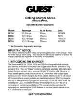
Installation
Allow at least 1 inch of clearance all around the
case for cooling. The best mounting conguration is
to mount the unit on a vertical surface oriented as
shown. Use #10 screws of the appropriate type for the
mounting surface to securely mount the unit.
The unit should be connected to your system as per
the drawing on the right.
See the following page for detailed hook up
instructions.
The case has 500 volts of isolation from both the input
and output, so it may be mounted on any surface
without fear of electrolysis or ground fault.
The unit is supplied with 1 metre (3 feet) of #10 AWG
wire. This should be adequate to connect to a breaker
panel or other source of power. If you need to extend
the wires, use at least #10 AWG wire and solder
and heat shrink the connection to protect the joint.
Connect the Red wire(s) to Positive, and the Black
wire(s) to Negative. , use a 30 amp panel breaker to
feed power to it.
To reduce radio noise to the absolute minimum, it may
be necessary to bond the case to the vessel ground.
To do this, remove one of the screws that mounts the
output terminal strip to the chassis. Then place a #6
ring terminal with a ground wire crimped to it under
the screw head, and replace the screw.
It is recommended to keep all wiring as short as
possible to keep the line losses to a minimum.

8
Operation
To turn the unit on, simply move the power switch to the ON position. The alarm buzzer will
sound and the Low Input LED will come on briey, and then the green Output ON LED will
illuminate.
When the unit is rst turned on, it will charge the batteries at a constant current of up to
25 or 50 amps depending on the depth of discharge of the battery bank. During this time,
the red ‘Charging’ LED will be on. If the batteries are seriously discharged, the ‘Low Output’
LED and the audible alarm will also come on. After a period of time, which may be minutes
to hours, the batteries will reach the oat voltage, and the charging current will reduce as
necessary to maintain the batteries at that voltage. Once this happens, the red ‘Charging’
LED will go off. You may now check the oat voltage at the output terminals of the unit with
a good digital voltmeter. The oat voltage should be one half of the oat voltage from your
charger. Please note that the battery equalizer will work with or without your battery charger
hooked up. It will maintain the lower half (12 Vdc) of the battery bank at the same state of
charge as the upper half of the 24 Vdc battery bank.
the battery bank as the negative input and output connections are internally connected. If you
accidentally connect a battery in reverse, the output fuses (AGC 30) will blow. If this happens,
correct the connection of the battery, conrm it with a voltmeter, and then replace the fuse.
Connect the black ‘-’ input wire to your system as is shown in the drawing on the previous
page.
Hook Up Instructions:
You can ONLY connect one bank of batteries to the unit. Connect both the ‘+’ outputs of the
unit to the positive lead of the 12 Volt battery in the 24 Volt battery bank (see diagram on
previous page). It is not necessary to connect the ‘-’ output of the unit to the negative lead of
O
N
/O
F
F
INPUT POWER (24Vdc)
RED
BLACK
OVERLOAD
OVERTEMP
LOW OUTPUT
LOW INPUT
POWER
To 12Vdc Battery
To 12Vdc Battery
OUTPUT
FUSE
OUTPUT
FUSE
INPUT
FUSE
TO
REMOTE

9
Troubleshooting
Dry Contact Relay
If the red Over-temperature LED and the audible alarm come on, the unit has overheated,
and it will shut down until it cools off sufciently. You may not have allowed sufcient space
around the unit for cooling, or there may be too many devices connected to the output of
the unit. Either reduce the number of devices connected to the unit, or reposition the unit for
better cooling. If necessary, direct a stream of moving air over the unit.
If the yellow Low Input LED comes on, the input voltage has dropped below 19 VDC. To keep
from completely discharging the batteries (if the battery charger is being operated from
batteries), the unit will shut down until the voltage recovers to 21 VDC. Make sure that the
charging system is operating properly, and that the wires connecting the input voltage to the
unit are not corroded or damaged.
The dry contact relay will change state to indicate that there is not output from the charger.
To use your dry contact output fail relay you must connect a 9-pin D connector to the unit. You
must use pins one and six as is indicated on page 7 in the remote connector schematic.
The relay is factory preset to fail in the closed position when the low output LED and buzzer
come on. If you wish to have the relay fail in the open position when the low output LED and
buzzer come on, you must take the cover off the unit and move the jumper to the other position
on J5. J5 is located next to the relay.
To change the position of the jumper, rst turn the unit off and disconnect the unit from both
the power and batteries. Next, turn the unit on for 30 seconds to discharge the capacitors,
then turn it off again. Turn the unit upside down and remove the four screws. Remove the
cover and locate J5. It will be next to the relay as is shown in the above diagram. Simply move
the jumper to the desired position as is shown in the above diagram. Replace the cover and
re-install the four screws. Reconnect the unit to the power and batteries.

10
Remote Control Option
A remote control panel may be connected to the inverter using a 9-pin D-connector, which
attaches to the front panel of the battery charger. The remote control panel and D connector
are part of the remote control option. The remote control panel allows the unit to be operated
remotely as well as duplicating all the diagnostic indicators and audible alarm.
REMOTE CONNECTOR
This connector is located on the side of the unit. Important: To prevent the possibility of High
Voltage Electrical Shock, do not power up the battery charger unless all wiring from the unit to
the remote is securely connected. Do not remove the dust cover from the DB-9 connector if the
remote is not being used.
IMPORTANT: This remote is to be used
only on Battery Chargers manufactured by
Analytic Systems.
If the red Charging LED, the Low Output LED and the audible alarm come on, and the green
Output On LED is completely off, the output of the unit has been shorted out, or there has been
an internal failure. Turn the unit off, disconnect the charging battery bank(s) connected to it,
and turn it back on again. If it comes on normally, then either one of the battery banks or the
output connections have become shorted. To determine the cause of the fault, rst check to be
sure that the output terminals are not shorted, then reconnect the battery banks one at a time
to see which battery bank is the cause of the fault. If one of the battery banks is the cause
of the short it must be replaced. If the condition still exists even after the battery banks have
been disconnected, the unit is defective, and must be returned to the factory or an authorized
service center for repair.
If the unit will not turn on at all, check the input fuse. If it is blown, replace it with a new one.
If that fuse blows as well or the unit still will not turn on, it is defective, and must be returned
to the factory or an authorized service center for repair.
If the green ‘Output On’ LED is on, but there is no voltage at the output terminals, check the
output fuses. If they are blown, replace them with AGC 30A fuses. If there is still no voltage
at the terminals, the unit is defective, and must be returned to the factory or an authorized
service center for repair.

11
Limited Warranty
1. The equipment manufactured by Analytic Systems Ware (1993) Ltd. (the “Warrantor”) is warranted to be free
from defects in workmanship and materials under normal use and service.
2. This warranty is in effect for:
a. 3 Years from date of purchase by the end user for standard products offered in our catalog.
b. 2 Years from date of manufacture for non-standard or OEM products
c. 1 Year from date of manufacture for encapsulated products.
3. Analytic Systems will determine eligibility for warranty from the date of purchase shown on the warranty card
when returned within 30 days, or
a. The date of shipment by Analytic Systems, or
b. The date of manufacture coded in the serial number, or
c. From a copy of the original purchase receipt showing the date of purchase by the user.
4. In case any part of the equipment proves to be defective, the Purchaser should do the following:
a. Prepare a written statement of the nature of the defect to the best of the Purchasers knowledge, and
include the date of purchase, the place of purchase, and the Purchasers name, address and telephone
number.
b. Call Analytic Systems at 800-668-3884 or 604-946-9981 and request a return material authorization
number (RMA).
c. Return the defective part or unit along with the statement at the Purchasers expense to the Warrantor;
Analytic Systems Ware (1993) Ltd., 8128 River Way, Delta, B.C., V4G 1K5, Canada.
5. If upon the Warrantor’s examination the defect proves to be the result of defective material or workmanship,
the equipment will be repaired or replaced at the Warrantor’s option without charge, and returned to the
Purchaser at the Warrantor’s expense by the most economical means. Requests for a different method of return
or special handling will incur additional charges and are the responsibility of the Purchaser.
6. Analytic Systems reserves the right to void the warranty if:
a. Labels, identication marks or serial numbers are removed or altered in any way.
b. Our invoice is unpaid.
c. The defect is the result of misuse, neglect, improper installation, environmental conditions, non-autho-
rized repair, alteration or accident.
7. No refund of the purchase price will be granted to the Purchaser, unless the Warrantor is unable to remedy the
defect after having a reasonable number of opportunities to do so.
8. Only the Warrantor shall perform warranty service. Any attempt to remedy the defect by anyone else shall
render this warranty void.
9. There shall be no warranty for defects or damages caused by faulty installation or hook-up, abuse or misuse of
the equipment including exposure to excessive heat, salt or fresh water spray, or water immersion except for
equipment specically stated to be waterproof.
10. No other express warranty is hereby given and there are no warranties that extend beyond those described
herein. This warranty is expressly in lieu of any other expressed or implied warranties, including any implied
warranty of merchantability, tness for the ordinary purposes for which such goods are used, or tness for a
particular purpose, or any other obligations on the part of the Warrantor or its employees and representatives.
11. There shall be no responsibility or liability whatsoever on the part of the Warrantor or its employees and rep-
resentatives for injury to any person or persons, or damage to property, or loss of income or prot, or any other
consequential or resulting damage which may be claimed to have been incurred through the use or sale of the
equipment, including any possible failure of malfunction of the equipment, or part thereof.
12. The Warrantor assumes no liability for incidental or consequential damages of any kind

8128 River Way, Delta B.C. V4G 1K5 Canada T. 604.946.9981 F. 604.946.9983 TF. 800.668.3884 (US/CANADA)
www.analyticsystems.com
An ISO9001 and AS9100 Registered Company Battery Chargers • Inverters • Power Supplies • Voltage Converters
/